Building Movement Joints and BIM


Vertical displacement. It is important to realize that buildings can move in all directions (see Figure 1). Movement of a building in the vertical direction might occur from thermal or moisture impacts as described above, but it is likely to be more significant if differing soil and foundation conditions are encountered across a building. Different portions or wings of a building may be of different heights and sizes and therefore will likely have different types of foundation designs. Where these different foundations meet, there may be a difference in the rate or amount of settlement that occurs on between the two. This condition might also apply or be exacerbated by different soil conditions that respond differently to the building loads imposed on them. The differences are usually calculable and can be accommodated in the design, but allowing for the vertical displacement that may occur regardless of the compensating design, is obviously more prudent.
Lateral shear. Horizontal forces on a building can come from things such as wind loading or external building attachments. These forces can be accounted for in the basic structural design, but it may well be within normal tolerances to allow for some level of movement, particularly at extreme "worst case" conditions.
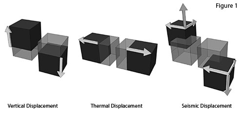 |
Forces in buildings can exert stress and strain along a vertical axis, along multiple horizontal axes, or in multiple directions during a seismic event. Illustration: Nystrom, Inc. |
Â
Seismic forces. Designing a building to survive the multiple forces of an earthquake is clearly more involved than a single directional force. Seismic forces can affect a building in any direction along multiple horizontal and vertical axes. The degree of these forces that need to be addressed are mandated by codes and good structural system design standards. Allowing portions of a building to move independently from one another during an earthquake is a proven method to address the impact of those seismic forces.
Construction forces. Certain materials may experience or exert particular forces during construction. For example, the chemical process of concrete curing causes it to shrink and possibly crack. Masonry may swell and shrink during installation and set up. Materials that are designed to be used in spaces that are heated and cooled may be subject to weather conditions during construction that they weren't otherwise designed for. All of these potential construction forces need to be taken into account.
Degrees of Separation
The fundamental approach of separating a material, a building system, or the building itself into independent portions or sections is the starting point for all movement joint discussions. This requires a basic understanding of different types of joints, their general impact on the building, and where they are used. BIM can be an incredibly useful and important tool not only to locate key areas where different joints should be used, but also to detail and integrate the joints into the rest of the construction. Full three dimensional modeling of a building will demonstrate critical areas for joints to occur between the structural system and other materials and building systems. Integration of the details of these joints will necessarily need to be cross discipline affecting the design of the structure, architecture, interiors, roofing, and in some cases, the mechanical systems. Hence the cross-discipline capabilities of BIM will prove highly valuable in correctly locating and coordinating the design of building joints of all types. It is important to acknowledge that the joint must be calculated and sized in terms of its minimum and maximum opening, with the average opening often being its nominal size (see Figure 2). The common types of joints are described below in terms of the type of gap or separation that is needed. In the subsequent section we will discuss how to fill, cover, or otherwise treat these joints.
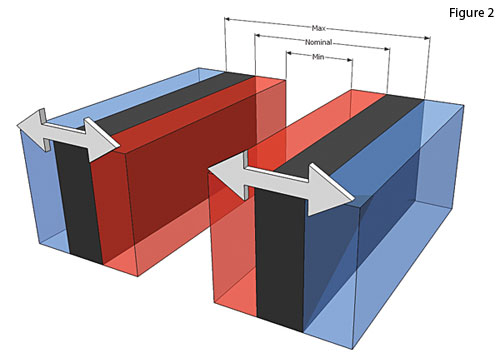 |
The use of BIM can help determine the nominal, minimum and maximum joint size and show the impact of expansion and contraction on building systems. Illustration: Nystrom, Inc. |
Notice


