Building Movement Joints and BIM


Integrating Joints into Buildings: Fill, Cover, or Conceal?
So far, we have described the physical joints or separations in structural and architectural materials and systems. If we were to stop at this point and look at our BIM model, we would see literal gaps and openings in our walls, floors, roofs, etc. Similarly, at a partially complete point in the actual construction, we should also see exactly those intentional gaps. However, to get to the finish stage, those gaps need to be dealt with in order to address the other needs of the building such as creating a weathertight building envelope, maintaining fire separations, or providing a finished surface consistent with the aesthetics of the rest of the building. Fortunately, there are a wide variety of choices and customized products available to architects and designers to choose from including filling, covering, or partially concealing these joints. The details of each method are different not only for the type of system or product used, but they also have different impacts on the details of the materials forming the joints that need to be coordinated. This is a situation where the use of BIM can make the process of design much easier. Manufacturers of building movement joint products have created BIM families of their products that can be referenced, tried, coordinated, and fully integrated into the full model. In the process, details of opening width, any needed special edge conditions, etc. can be determined and coordinated to assure that the joint is designed and constructed to perform successfully.
Our next step in the process of designing joints into buildings, then, is to choose the appropriate method of treating the gaps from the common choices below:
No fill. In cases where the joint does not fully penetrate the material, as in a concrete control joint, there may be no need to fill in the joint. Rather, the joint is cut only into the surface and is able to either channel away any water (as in a sidewalk), designed to be part of the finished surface (as in a sealed interior concrete slab), or covered over (as in a floor slab with flooring on top).
Filler systems. In situations where a filler is clearly needed, it may be appropriate to use a flexible or compressible material that is adhered or anchored to the adjacent building materials (see Figure 6). As the building elements move, the filler compresses or expands in one or more directions while still staying consistently and uniformly secured to those materials. Essentially, there are two general options to consider. For small gaps of about 1/2 inch or less, a backer rod and flexible sealant (such as silicone) are an appropriate and common solution. In cases where multiple wythes of masonry are involved, a flexible spline or waterstop may be warranted in addition to the sealant. For larger openings, a preformed elastomeric or other compressible filler is appropriate. These fillers are manufactured items that can come with or without aluminum frames depending on the application and the requirements. All manufactured fillers of this type will have a specific range of expansion with a minimum and maximum size that it can accommodate, meaning that it needs to be matched to a joint that falls within that range of calculated movement. These products can be used to fill gaps ranging from 1/2 inch up to approximately 6 inches in floors and 24 inches in walls. Filler products can be selected from numerous choices based on varying needs for durability, weather-sealing, finish color, and resistance to different forces. Unframed compressible fillers can either be solid-shaped material or extruded in a multiple "bellows" form that is adhered to the sides of the joint. If a framed filler is used, it is typically screwed or anchored into the adjacent materials allowing the filler to bridge the space between the frames, again using either a solid or bellows-style filler material.
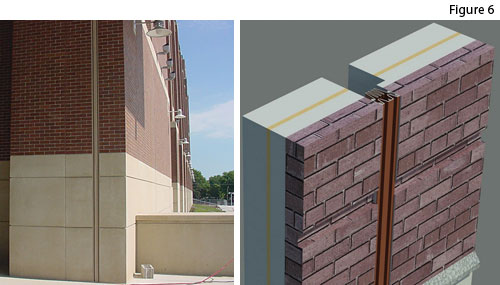 |
Flexible filler installed in a building movement joint shown in place on the left and in a BIM illustration on the right Photo and BIM illustration: Nystrom, Inc. |
Notice