Building Movement Joints and BIM


Slide-by cover systems. An alternative to filling a joint is to cover over it with an arrangement of metal plates that slide past one another (see Figure 7). In this manner, there is not necessarily a filler material that is being compressed and expanded. Instead, each metal plate is secured on only one side allowing the overlapping sections to move or slide by each other such that the movement can occur while still keeping the gap covered. The metal plates can come in a variety of finishes, durability, and colors to accommodate different applications. While commonly referred to as expansion joint covers, these covers can in fact be used to accommodate other types of joints as well such as abutment joints and building separation joints for a variety of forces including seismic activity.
Concealed cover systems. In some cases, the preferred approach for design and aesthetic reasons is to conceal a substantial portion of the cover thus leaving only very little metal exposed. This approach is often very desirable when expansion joints or building separation joints are required that are very wide (2 inches or more). The partial concealment of the metal is typically accomplished through a recessed section of the cover that allows for finish material such as flooring or wall covering to be inserted and adhered. This finish material can match the surrounding surfaces or provide an intentional accent color. Detailing and installing these systems correctly is obviously important since installing the finish material improperly over the moving portions of the cover will undoubtedly crack or break that material into pieces. Treating joints in this manner is a case where manufacturer's information and incorporating the product into a BIM model are extremely useful both to help with the technical installation details and to visualize the finished design appearance.
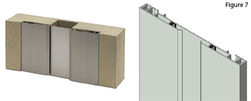 |
Slide-by metal covers installed in a building movement joint Photo and BIM illustration: Nystrom, Inc. |
Â
Detailing for Specific Locations Using BIM
In the design of a building, we have now identified the need to first recognize and deal with the forces that cause movement in a building. We've looked at the different types of joints or gaps that can be used to allow or dissipate those forces, and the approaches that can be used to fill or cover those gaps in order to accommodate the other general needs of a building. The final step in designing and specifying building movement joints is to select and detail the specific products or assemblies appropriate to the different locations where they are needed. BIM has been referred to as a way to investigate the options and visualize the alternative conditions thus far. Now it is appropriate to use it to make the final selections and assure that all conditions are fully coordinated. Because there are many manufactured joint products that are available in BIM format, it is more straightforward than ever to use this available library to make a final selection and in some cases actually customize the product to suit a project's needs. In particular, it is increasingly common that manufacturers will offer coordinated floor, wall and ceiling systems that match in appearance and finish. The benefit to the building design, then, is a consistent, continuous appearance across different building surfaces and adjacent materials. Using the manufacturer's BIM files in the overall computer model will allow for full visualization of this appearance on the different affected surfaces and allow the designers to make the best informed decisions on product selection.
Six specific joint locations are discussed below with some corresponding selection criteria to consider when choosing which ones to specify. Each of these assumes that the types of forces (horizontal, vertical displacement, seismic, etc.) have already been identified and the type of joint needed (expansion, abutment, building separation, etc.) has been analyzed and determined.
Interior floor systems. (See Figure 8.) Among the first criteria to consider for joints in active floors is how much traffic and what type will pass over it? Schools and auditoriums will be subject to a lot of pedestrian traffic. Airports, hotels and hospitals will add any number of wheeled devices to the traffic mix that need to be considered. In airports, this could include a range from heavy but large wheeled motorized equipment such as multi-passenger carts down to small wheeled items like suitcases with concentrated loads. Hospitals will have a similar range from large wheeled beds and gurneys down to small wheeled rolling monitor and equipment stands. Warehouses, manufacturing plants, and retail locations may have truly heavy-duty traffic such as forklifts and delivery carts. Each type of traffic will have a different overall impact on the floor joint system and different resulting direct impact based on the actual pounds per square inch exerted, ease of the wheels passing over the joint, etc.
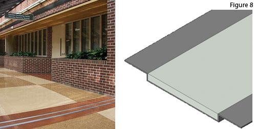 |
An interior floor joint cover in place on the left and in BIM detail on the right. Photo and BIM illustration: Nystrom, Inc. |
Notice