This CE Center article is no longer eligible for receiving credits.
Most regions of the United States face high wind hazards with the accompanying threat of wind-related damage to buildings. According to the Insurance Institute for Business and Home Safety (IBHS), high winds cause millions, if not billions, of dollars of damage each year.1 However, much of this damage could be avoided with a few affordable techniques designed to strengthen buildings against wind forces—techniques that account for interactions between wind loads and building material properties.
All buildings are at risk of experiencing damage during high winds. Each structure, with its own unique set of characteristics, such as stiffness, strength and shape, reacts differently to wind loads. However, wood is conducive to meeting the challenges of wind-resistive design. For example, one of wood's characteristics is that it can carry substantially greater maximum loads for short durations than for long periods of time,2 as is the case during high wind events. Wood buildings also tend to be comprised of repetitive framing attached with numerous fasteners and connectors, which provide multiple and often redundant load paths for resistance to wind forces. Further, when structural panels such as plywood or oriented strand board (OSB) are properly attached to lumber floor, roof and wall framing, they form diaphragms and shear walls that are exceptional at resisting high winds. In addition to their other advantages—such as cost-effectiveness and sustainability—properly designed and constructed wood structures complying with building code requirements have proven to perform well during high wind events.
For example, according to a report on building performance during the 2017 hurricane season by the Federal Emergency Management Agency (FEMA), most wood-frame houses built in accordance with the building code performed well structurally. For these buildings, load path was accounted for throughout the structure, including the connection of the roof deck to supporting trusses and rafters. Because of this, loss of roof decking on newer homes was rare.3
This continuing education course provides an overview of wind-resistive design issues in wood buildings with a focus on compliance with the 2018 International Building Code (IBC) and American Society of Civil Engineers/Structural Engineering Institute (ASCE/SEI) Minimum Design Loads for Buildings and Other Structures (ASCE 7-16). The information on code-conforming wood design contained in this course is based on the American Wood Council's (AWC's) 2015 National Design Specification® (NDS®) for Wood Construction, the 2015 Special Design Provisions for Wind and Seismic (SDPWS) and the 2015 Wood Frame Construction Manual (WFCM).
Structural Wind Loading
Structural wind loading requirements for buildings and other structures are specified in Chapter 16 of the IBC. The wind loading requirements are obtained primarily through reference to ASCE 7-16. The minimum requirements for wind loads must be used in design and are intended to ensure that every building and structure has sufficient strength to resist these loads without any of its structural elements being stressed beyond material strengths prescribed in the code. The code emphasizes that the loads prescribed in Chapter 16 are minimum loads and, in the vast majority of conditions, the use of these loads will result in a safe building. However, the code also recognizes that the designer may, and sometimes must, use higher loads than those prescribed to ensure a safe structure. The commentary to ASCE 7-16 is a good source to be consulted for additional information since it outlines conditions which may result in higher loading.4 In the event that wind speeds specified in the code are exceeded, there is an increased risk of structural damage and possibly failure despite the presence of safety factors in material design standards. For this reason, it is important to ensure that wind loads are properly determined.
Mapped Wind Speeds and Risk Category
Today's maps include more comprehensive analysis of wind speeds for both coastal and non-coastal areas than has ever been available. The ultimate design wind speed, Vult, in miles per hour (mph) for the establishment of wind loads is determined using wind speed maps contained in three IBC Figures: Figure 1609.3(1) for Risk Category II buildings, Figure 1609.3(2) for Risk Category III buildings, figure 1609.3(3) for Risk Category IV buildings, and Figure 1609.3(4) for Risk Category I buildings. Mapped wind speeds are based on the probability of winds attaining speeds in a geographic area, developed from an analysis of wind speed data collected during severe wind events assuming the following reference conditions: a height of 33 ft above grade and flat, open terrain with scattered obstructions (Exposure Category C) averaged over 3 seconds, i.e., 3-second gust wind speed. Over the years, mapping of wind speeds, along with characterizing effect of surrounding terrain, have evolved with research. For example, earlier maps of ASCE 7 and the predecessor model codes incorporated fastest-mile wind speeds, with fastest-mile being the average speed of one mile of air that passes a specific reference point, with gusts accounted for by pressure coefficients.5

Credit: ASCE. Portion of IBC Figure 1609.3(1).
Ultimate Design Wind Speeds, Vult, For Risk Category II Buildings and Other Structures

Photo: New Genesis Apartments, Killefer Flammang Architects, KC Kim, GB Construction
Wood buildings are often characterized by repetitive framing and numerous connections—which provide multiple, often redundant load paths for resistance to wind forces.
Starting with the 2012 IBC, the term “Risk Categories” replaced “Occupancy Categories,” the term used in previous editions. Risk Categories are used to categorize buildings and structures based on their importance and include considerations such as risk to human life and societal need of the building or structure to function during and following an extreme event. Mapped wind speeds for Risk Category III and IV buildings, for which the potential consequence of failure to human life and/or economic impact is greatest, are greater than mapped wind speeds for Risk Category II buildings. Mapped wind speeds for Risk Category II buildings are greater than for Risk Category I buildings, for which the potential consequence of failure to human life and/or economic impact is relatively small. So for proper design, it is critical to identify the risk category of the building or structure when choosing the wind speed map. The mapped wind speeds for Risk Category II buildings are illustrated on page 4. Detailed descriptions of buildings and structures associated with Risk Category I, II, III and IV are described in IBC Table 1604.5.
Using Wind Speed Maps
Mapped wind speed contour lines delineate wind speed increments of either 5 mph or 10 mph and are not intended to represent a zone's fixed wind speed. Linear interpolation of wind speed between contour lines is permitted. For example, a building situated halfway between the 120 mph and 130 mph contours could be designed for a wind speed of 125 mph based on linear interpolation. Alternatively, a design wind speed of 130 mph6 could conservatively be used.
Wind Loads on Buildings
Buildings and structures are designed and constructed to resist wind loads, i.e., wind pressure, as opposed to wind speeds. Wind speed, although a significant contributor, is only one of several factors that affect wind loads acting on a building that must be considered in proper design. Factors that affect the calculated design wind loads (pounds per square foot, or psf) include:
▶ Combined gust factor and external pressure coefficients (GCpf) for low rise buildings
▶ Combined gust factor and internal pressure coefficients (GCpi)
▶ Design velocity pressure
Design velocity pressure varies based on the following factors:
▶ Mapped wind speed (which can vary by risk category for a given location)
▶ Exposure category
▶ Topographic effects
▶ Wind directionality
▶ Elevation factor
In addition, wind loads may vary based on the building's response characteristics. Provisions of IBC Section 1609 apply only to structures of shapes that do not have unusual response characteristics and which are located on sites that are not subject to channeling effects or buffeting in the wake of upwind obstructions. Channeling, for example, would occur when wind speeds are magnified due to the venturi effect as they are directed between tall buildings, thus subjecting downwind structures to higher wind speeds. Should unusual circumstances exist, the design wind loading must be determined by wind tunnel tests or nationally recognized data.
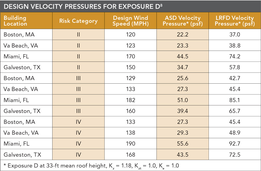
As an example of design velocity pressures for specific building locations and risk categories, consider the tables on page 4. All locations identified are within the hurricane-prone region with the exception of Dallas, Texas. As can be seen, for a given location, design velocity pressure in accordance with Equation 1 varies by risk category and exposure category (see Figure below). For example, for Exposure C in West Palm Beach, Fla., a Risk Category II building has a design wind speed of 170 mph while Risk Category III buildings have a design wind speed of 182 mph and Risk Category IV buildings have a design wind speed of 190 mph. Further, design velocity pressures vary for the same risk category when the exposure category changes. And, as can be seen, design velocity pressures for buildings subject to Exposure D are noticeably higher than for Exposure C.
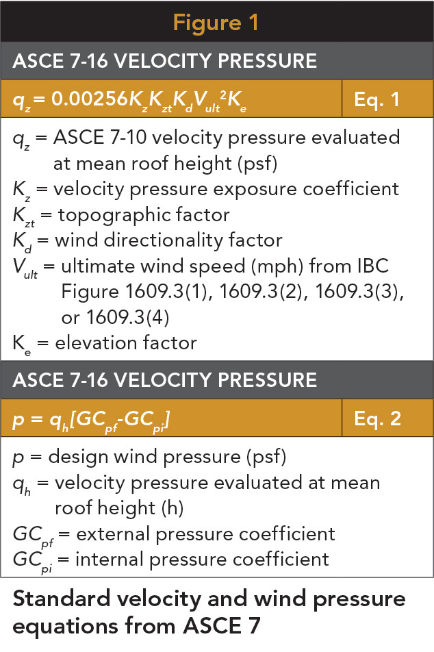
Standard velocity and wind pressure equations from ASCE 7
Photo: FEMA 488, Mitigation Assessment Team Report, Hurricane Charley in Florida
After Hurricane Charley, FEMA noted no structural damage to new wood-frame buildings built to the 2001 Florida Building Code standards.
Surface Roughness and Exposure Categories
One of the basic decisions in the design of wind-resistive buildings is determination of exposure category based on the roughness of nearby terrain. For each wind direction considered, an exposure category that reflects the characteristics of terrain surface irregularities must be determined for the site at which the building or structure is to be constructed. The concept of exposure categories provides a means by which to define the relative roughness of the boundary layer. The land or water surface adjacent to the building site exerts a drag force on wind due to obstructions that retard the flow of air close to the surface. The reduction in the flow of air is a function of height above the terrain surface and terrain roughness. Wind speeds increase with height above the terrain. The relationship between height above the water or ground and wind speed is exponential. The rate of increase in wind speeds with height is a function of the terrain features. The rougher the terrain, the shallower the slope of the wind speed profile. The smoother the terrain, the steeper the slope of the wind speed profile.
Categories are used to define this roughness in the boundary layer. The surface roughness within each 45-degree sector around a building site. must be determined for a distance upwind of the site for the purpose of assigning an exposure category. Exposure B is the most common exposure category in the country. Therefore, Exposure B is often the default exposure category. But it is important to recognize that exposure category varies based on conditions at the site and that buildings are often sited on properties of Exposure C and D with attendant higher wind loading.
Over the past decade, there has been significant research in exposure categories associated with shorelines in hurricane-prone regions. Exposure C is used along the hurricane-prone coastline, while Exposure D is limited to coastal Great Lakes and other areas where wave heights are assumed to relatively small and inconsequential to wind flow. Historically, Exposure C was used along the hurricane-prone coastline, while Exposure D was limited to coastal Great Lakes and other areas where wave heights were assumed to be relatively small and inconsequential to wind flow. Wave heights in oceans and Gulf of Mexico waters are significant at the water's surface during a hurricane, thus producing substantial surface obstructions and friction which reduce the wind speed near the surface.
Topographic Effects
In calculation of wind loads, topographic effects are accounted for by use of the topographic factor, Kzt. The topographic factor accounts for observations from research and field experience that wind speeds can increase significantly due to topographic effects with the wind speed increase known as a wind speed-up effect. A recognized topographic effect is that buildings located on the upper half of an isolated hill or escarpment may experience increased wind speeds, or wind speed-up, from those for the same building located on level ground. Due to the location-specific nature of the topographic effect, prescriptive solutions for resistance to wind forces are typically based on an assumed topographic effect factor of 1.0.
Wind Directionality
For most wood-frame buildings with wind loads determined in accordance with ASCE 7 load combinations, the effect of wind directionality is accounted for by use of a wind directionality factor, Kd, equal to 0.85. In accordance with ASCE 7 Commentary, the wind directionality factor accounts for two effects: “(1) the reduced probability of maximum winds coming from any given direction and (2) the reduced probability of the maximum pressure coefficient occurring for any given wind direction.”
Elevation Factor
A new elevation factor has been added in ASCE 7-16 that accounts for changes in air density at elevations above mean sea level. The revised standard has a table of Ke factors for elevations up to 6000 ft. and a formula used to calculate the Ke factor for any elevation.
Effect of Openings on Internal Pressure Coefficients
Openings in the building envelope also affect the wind pressures imposed on building elements. The presence of openings in the building envelope can have a significant affect on the magnitude of the total wind pressure required to be resisted by each structural element. Depending on the location and size of openings with respect to wind direction and building porosity, external and internal pressures can act in the same direction to produce higher forces on the walls and roof. An example of this effect of openings is illustrated in Figure below. In this scenario, pressures occur on both exterior and interior building surfaces as a result of a large opening in the windward wall of the building. According to this scenario, wind enters the building, exerting internal pressures (positive) against all interior surfaces. This opening has the net effect of producing high internal pressures that will act in the same direction as the external pressures on the roof and leeward walls, adding to the overall pressure on these building elements.
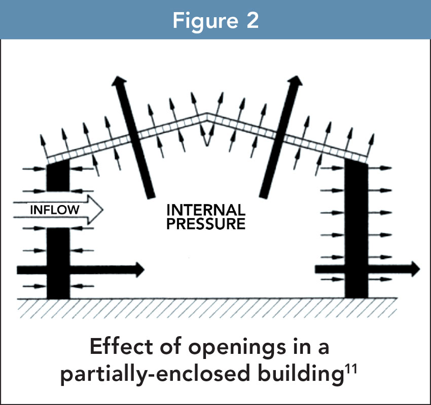
Image: Florida Building Code Commentary
Effect of openings in a partially-enclosed building11
Buildings are designed as being enclosed, partially enclosed or open. For most buildings, designs are based on the building envelope being enclosed. Open buildings are at least 80% open on every wall. Partially enclosed buildings are buildings in which:
a) The total area of openings in a wall that receives external pressure exceeds the sum of the areas of openings in the balance of the building envelope, and
b) The total area of openings in a wall that receives external pressure exceeds 4 sq ft or 1% of the area of that wall, whichever is smaller, and the percentage of openings in the balance of the building envelope does not exceed 20%.
Enclosed buildings are those that:
- have an opening on the windward wall that is less than 4 sq. ft. or 1% of the area of that wall, and
- where the balance of openings in the building envelope does not exceed 20%.
Partially open buildings are those that do not comply with the requirements for open, partially enclosed, or enclosed buildings. Enclosed and partially open buildings are not prohibited for having openings, provided such openings are small and distributed about the building envelope. Wind loads for typical wood-frame building structures, such as residences, offices and stores are usually based on the condition of the building being enclosed. The interiors of enclosed buildings, e.g., furnishings, equipment and merchandise, are protected from damage caused by wind and wind-driven rain by rated windows and doors.
Windows and doors are not considered openings if they are likely to be closed during a design storm event. Therefore, at a minimum, windows and doors need to be rated to resist the positive and negative design wind pressures. However, in certain hurricane-prone areas there are heightened risks associated with the likelihood of wind-borne debris breaking glazed openings. In such wind-borne debris regions, glazed openings must be impact resistant or protected with an impact-resistant covering, such as shutters, meeting the requirements of an approved impact-resistant standard such as ASTM E1996 and ASTM E1886.
External Pressure Coefficients
For the design of wood-frame buildings 60 ft in height or less, the “envelope procedure” for determining Main Wind Force Resisting System (MWFRS) loads is the most commonly used. External pressure coefficients from the envelope procedure have been developed to represent critical loads on the main structural elements, which are “enveloped” to reflect induced actions on a building from various wind directions for various building geometries, roof heights and roof slopes. External pressure coefficients for Component and Cladding (C&C), on the other hand, represent peak pressures which occur over small areas. Localized negative pressures associated with C&C loads will almost always control design of exterior sheathing and cladding elements, such as wall sheathing, wall cladding, roof sheathing and roof cladding and the attachment of the sheathing and cladding to the building's structural frame.
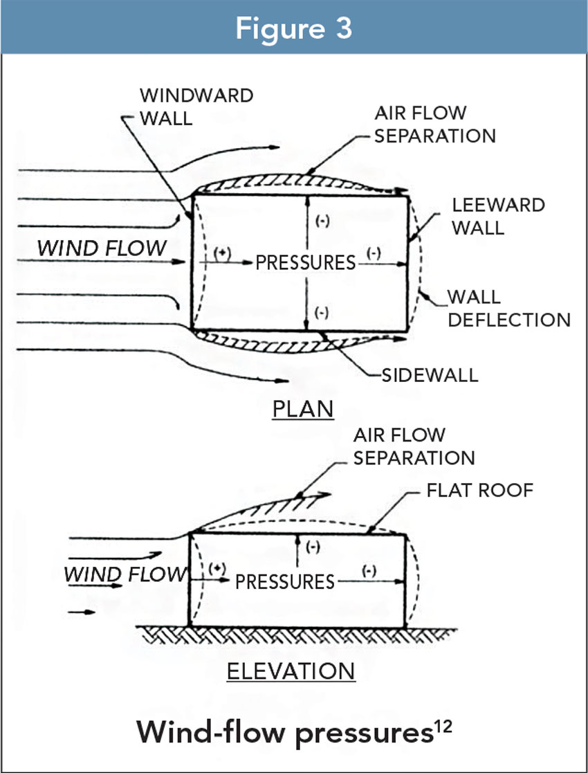
Image: Florida Building Code Commentary
Wind-flow pressures12
In accordance with ASCE 7, the MWFRS is “An assemblage of structural elements assigned to provide support and stability for the overall structure. The system generally receives wind load from more than one surface.” Examples of MWFRS elements include roof trusses, roof and floor diaphragms, and shear walls. Individual elements of the MWFRS may also be subject to C&C load requirements. These include sheathing, cladding, wall studs, individual roof rafters and elements of a roof truss, and short-span trusses resisting wind loads from cladding.
When wind encounters a building, the airflow changes direction and produces several varying effects on the building. Exterior walls and other vertical surfaces facing the wind (windward side) and perpendicular to its path are subjected to inward (positive) pressures (loads). The wind continues to flow around and over the building, resulting in outward (negative) pressures (loads). This phenomenon produces suction or outward pressures on sidewalls, the leeward wall and, depending on geometry, the roof.
Wind pressures on a roof vary based on roof slope and location on the roof with greatest wind pressures occurring at roof edges. Roof surfaces on the windward side with flat or shallow slopes are generally subjected to outward (negative) pressures. Moderately sloping roofs (up to 28 degrees) are subjected to an overall negative pressure. The windward side of high-sloping roofs respond similar to walls and sustain positive pressures, while roof sections on the leeward side are subjected to negative pressures. For sloped roofs where the wind direction is parallel to the ridge, the wind pressures act similarly to a flat roof where the roof is subject to outward (negative) pressure.
Increased Pressure at Edge Zones
The greatest wind pressures acting on a building are negative pressures (suction) and the locations of the greatest suction pressures occur at wall and roof edge zones as illustrated in Figure below. Edge zones at wall corners, roof ridge and roof perimeter represent locations of potentially high suction forces relative to the central portions of the wall or roof. The extent of increase in suction forces for roofs depends on roof geometry but increases of two or more times the negative pressures associated with central wall area are possible.
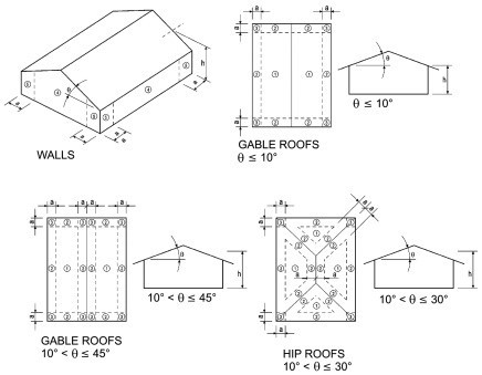
Image: Florida Building Code Commentary
Roof and wall sheathing zones for wind design
The maximum differences in wall pressures are between central pressures and edge zone pressures; however, the approximately 30% maximum difference will not usually necessitate different nailing schedules and sheathing thicknesses between portions of the wall in the edge zones and away from the edge zones. Wall sheathing thickness and spacing of fasteners attaching the sheathing to wall studs throughout the wall length are commonly based on higher end zone pressures to simplify installation. For example, reduced sheathing fastener spacing and potentially thicker sheathing necessary for resistance to higher edge zone pressures are commonly used throughout the wall length. Another technique to allow for use of a consistent sheathing thickness and spacing of sheathing fasteners is to reduce stud spacing in wall edge zones. The reduced stud spacing reduces the span of the sheathing between studs and also provides for more points of attachment of the sheathing to the framing for resistance to the higher edge zone suction pressures.
For roof sheathing and roof sheathing attachment, the increase in forces between edge zones and interior zones is larger than observed for walls. While wood structural panel sheathing of consistent grade and thickness is used over the length of the roof, two fastening schedules are often specified.
One fastening schedule is for roof areas outside edge zones where fasteners are spaced farther apart. A second fastening schedule is for higher wind pressure roof areas within the edge zones where fasteners are more closely spaced. The roof sheathing pressures developed from the external pressure coefficients in ASCE 7-16 are higher than in previous versions of ASCE, and thus require more attention to nailing patterns and to nail types and sizes. In some cases, Roof Sheathing Ring Shank nails are required for attachment of roof sheathing to roof framing for resistance to high wind uplift forces.
While generally considered to offer superior resistance to withdrawal from the framing than smooth shank nails, care should be taken to ensure that the ring shank nail specified has both adequate withdrawal strength to secure sheathing to roof framing for wind suction pressures and sufficient lateral strength to develop the required diaphragm behavior of the roof. The 2018 National Design Specification for Wood has specifications on these nails that must be followed.
These specifications have been developed specifically to address the high uplift pressures created by the ASCE 7-16 external pressure coefficients and are referenced in the 2018 Wood Frame Construction Manual. Standard or generic threaded nails do not meet the stringent requirements of the NDS specification.

Photo: Dreamstime
While wood structural panel sheathing of consistent grade and thickness is used over the length of the roof, two fastening schedules are often specified—one for roof areas outside edge zones and a second for higher wind pressure roof areas within the edge zones where fasteners are more closely spaced.
Continuous Load Path
Building scientists use the term “load path” to describe how forces flow through a building's structure to the final point of resistance at the foundation. A continuous load path for all wind forces acting on the building must be established for reliable building performance.
A continuous load path must be provided to adequately pass wind forces through the building's structural elements from the roof to the foundation and, ultimately, to the soil below. In wood-frame buildings, the continuous load path is created by a system of wood framing, structural sheathing, metal connectors, fasteners (such as nails and screws), diaphragms and shear walls. A continuous load path is like a chain that ties building elements together from the roof to the foundation for both wind shear forces and wind uplift forces. A continuous load path is critical during a high wind event because it helps hold the building together. Anchorage must be provided at appropriate locations to resist wind-induced actions, such as overturning, uplift and sliding. Resistance to wind uplift and overturning is provided by the dead load of and within a building, including weight of foundations and any soil directly above them. However, only the dead load likely to be in place during a design wind event is permitted to be used in design. This requires the designer to exercise caution in using dead loads. Previous editions of the code specified that the overturning moment and sliding due to wind load could not exceed two-thirds of the dead load stabilizing moment. Today, the use of reduced dead loads for resistance to wind induced forces is accomplished through load combinations of IBC 1605.1.
Wood Design Standards
The design of a continuous load path is accomplished by use of code-referenced wood design standards for members, connections, shear walls and diaphragms.
The design standard for wood construction referenced by the IBC is the National Design Specification (NDS) for Wood Construction, published by the American Wood Council (AWC). It includes the necessary design procedures and design value adjustment factors for beams, columns, joists, structural glued laminated timber, timber piles, prefabricated I-joists, structural composite lumber, cross laminated timber, and connections, for lateral (including wind and seismic) and gravity loads and certain special loading conditions. It also contains design procedures for calculated fire resistance of exposed wood members. Reference design values for structural sawn lumber, structural glued laminated timber and round timber poles and piles are contained in the NDS Supplement, a compendium of design values as reported by the grading agencies responsible for their establishment.
Another AWC standard integral to wind design, is the Special Design Provisions for Wind and Seismic (SDPWS). It is directly referenced by the IBC for the required design of lateral force-resisting systems such as nailed wood-frame shear walls and diaphragms which resist wind, seismic or other lateral loads. Section 2305 of the IBC contains additional criteria, primarily for stapled shear wall and stapled diaphragm construction.
The AWC Wood Frame Construction Manual for One- and Two-Family Dwellings (WFCM) provides engineered and prescriptive design requirements and is referenced by the IBC and the IRC. The provisions of the WFCM are based on dead, live, snow, seismic and wind loads derived from the provisions of ASCE 7-16. In general, the framing systems described in the WFCM utilize repetitive member wood assemblies. Although intended for one- and two-family dwellings, the WFCM is a useful tool in the design of non-residential buildings that fit within its scope for building size and assigned loads. The expanded applicability of WFCM design information beyond one- and two-family dwellings is recognized in 2018 IBC Section 2309.
Conclusion
Designing a building to withstand the potentially devastating forces of high winds is one of the greatest challenges an architect or engineer can face. Each structure, with its own unique characteristics and site conditions, reacts differently to wind loads—and many complex and interrelated issues must be considered to ensure that a building is truly wind-resistive.
As discussed in this course, wood is a proven choice for wind-resistive construction. Experience has shown that code-compliant wood buildings perform exceedingly well during high wind events such as hurricanes. Wood is strong and most wood-frame buildings offer the advantage of repetitive members and multiple connections, which together create redundant load paths to effectively transfer wind forces from the building envelope to the foundation and soil below.
For the latest research on wood buildings and wind, please visit research.ThinkWood.com.
Endnotes
1. https://disastersafety.org/hurricane/
2. 2015 National Design Specification (NDS) for Wood Construction, Section 2.3.2.1
3. MAT Compendium Report, 2017 Hurricane Season, Building Performance Observations, Recommendations, & Technical Guidance, FEMA P-2054, Sept 2019.
4. Basic wind speeds need to be increased where records or experience indicate that the expected wind speed is higher than those reflected in the Figures referenced in Section 1609.1 of the IBC. Ultimate design wind speeds, Vult, for special wind regions indicated near mountainous terrain and near gorges shall be in accordance with local jurisdiction requirements, in accordance with Section 26.5.2 of ASCE 7. In non-hurricane-prone regions, Vult can be determined in accordance with Section 26.5.3 of ASCE 7.
5. The change from fastest-mile wind speed map to a 3-second gust map was necessary for several reasons, foremost of which was that weather stations across the United States ceased collecting fastest-mile wind speed data.
6. Some jurisdictions may, for simplicity of enforcement, default to a single wind speed for all locations between contours. In this case, they would be required to use 130 mph.
7. Philip Line and William L. Coulbourne, ASCE 7-10 Wind Provisions and Effects on Wood Design and Construction, American Wood Council, 2012
8. Ibid
9. Taking Shelter from the Storm: Building a Safe Room for Your Home or Small Business, FEMA P-320, Fourth Edition, 2014
10. Safe Rooms for Tornadoes and Hurricanes: Guidance for Community and Residential Safe Rooms, FEMA P-361, Third Edition, 2015
11. Figure 1609.1.4, Florida Building Code Commentary – 2004, Vol. II, page 16-31
12. Figure 1609.1, Florida Building Code Commentary – 2004, Vol. II, page 16-25
13. Spring 2011 Tornadoes: April 25-28 and May 22, Building Performance Observations, Recommendations and Technical Guidance, FEMA P-908, May 2012

|
Think Wood is a leading education provider on the advantages of using softwood lumber in commercial, community and multifamily building applications. We introduce innovators in the field to our community of architects, engineers, designers and developers. For support or resources, contact us at info@ThinkWood.com.
|