New Elevator Technology: The Machine Room-Less Elevator


Â
|
Â
Energy conservation is further achieved through other efficiencies. Elevator door operators are designed with more efficient permanent-magnet synchronous drive motors that require less power to operate than conventional door systems. These solutions feature a drive motor centered directly above door panels and a simplified torque transmission that eliminate complicated cam mechanisms.
Meanwhile, environmental considerations continue to impact future systems. Manufacturers worldwide are working toward developing more reliable designs for elevators that have a longer operating life and use less energy.
Â
Â
|
Â
MRL Design Considerations
Faced with MRL patents held by competitors, manufacturers have developed different solutions for utilizing PMSM machines, suspending the cab, and locating the machine, controls and counterweight. The result is that building requirements can vary for different MRL product lines.
Architects should, therefore, consider the following when adding MRLs to existing structures or integrating MRLs in new construction:
- Different MRL manufacturer dimensions. During design and specification phases, architects should be aware that manufacturers have different dimensions for shaft footprints, pit size and overhead space. Designers are advised to plan for the worst-case scenario and allow for maximum dimensions. This will also allow for multiple competitive bids and manufacturer substitutions as needed.
- Interior cab design is governed by limitations on cab weight. This could impact the architects' own custom design and choice of finishes for the interior cab. Because MRL machines are smaller than traditional traction models, permissible cab weight is less than with traditional traction machines. Cab weight is derived from calculations involving speed, number of stops and varies according to application.
- Power usage impacts electrical requirements. Unlike a hydraulic elevator that may require a 25 hp to 60 hp motor, an MRL elevator operates on a much smaller machine. This will reduce the size of the main line feeder and emergency generators.
- Ventilating and cooling. Some integral MRL configurations place the controller in the front wall at the top landing; in these cases a grate built into the back provides needed ventilation. Others locate the controller in an adjacent closet, which may require that ambient temperatures be maintained within manufacturer's guidelines.
- Controller location. As a general rule, the controller can be located within 100 wire feet from the machine. This gives designers the flexibility of locating the controller as needed within this range to free up valuable square footage or create a desired space layout. Architects should be aware that placement of the control room should be checked for local code compliance, as some authorities have yet to adopt the national ASME code.
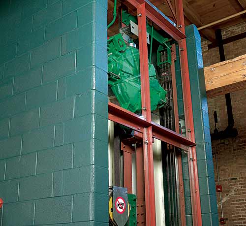
- Machine location and structural loading. Designers should know the location of the MRL machine since it may impact the building's structural requirements. One manufacturer mounts the machine on the guide rails, which, by transferring weight down to the pit floor, creates no overhead structural loads. Another manufacturer suspends the machine from one or more beams tied into the building in the overhead area, which impacts structural calculations and could add to building infrastructure costs.
- Construction coordination. The sequence of construction phases differs depending upon the MRL manufacturer and can affect the construction schedule. In one case, an MRL can be assembled from inside the hoistway once the shaft is built and capped. In other instances, manufacturers require the cap be left off of the hoistway in order to install the machine and its required beam arrangement by crane. It is typically the responsibility of the general contractor to provide the use of a crane for these applications.
- State and local code approval may be required. If the local code authority has not adopted the national 2005 Supplement to ASME 17.1/CSA B44-2007 Safety Code for Elevators and Escalators, approval on a case-by-case basis may be required. Further, certain manufacturers provide alternative suspension systems to traditional steel ropes that may require review by local code authorities.
Â
Â
Notice


