This CE Center article is no longer eligible for receiving credits.
Reportedly dating back to Archimedes, early prototypes of the elevator were installed in the royal palaces of Europe some 400 years ago. But it was not until the mid-19th century that the first modern elevators appeared in New York buildings, its technology driven by the need to move raw materials. Now, elevators are a standard feature for most commercial and public buildings of more than a single floor.
While technological advances were pushing many industries into new eras, elevators did not change significantly beyond a few system innovations. There was little reason why they should because the traditional technology worked-albeit with energy inefficiencies and significant space requirements. But, as manufacturers started focusing on the real costs of energy and hiding valuable real estate square footage inside hoistways and machine rooms, it responded, about 10 years ago, by introducing a new system. Named the Machine Room-Less (MRL) elevator-as the name implies, it does not require a machine room-the new elevator system saves space, is far more energy-efficient and avoids using polluting fluids. As owners increasingly demand energy savings and seek U.S. Green Building Council LEED® certifications, architects would do well to understand the features of the MRL and how to integrate it into their building design. Elevators fall into three general categories: hydraulic, traction and MRL.
Hydraulic Elevator
Passenger elevators generally employ two kinds of hoist mechanisms: hydraulics or roped traction systems. A Hydraulic elevator's function is based on Pascal's law of the incompressibility of fluids (the principle of hydraulics): an above-ground or in-ground piston mounted inside a cylinder is pressurized to raise and lower the car. Hydraulic systems are commonly used in low-rise buildings up to five stories. Speeds rarely exceed 150 feet per minute (fpm).
Originally the fluid used to drive the piston was water, hence the name hydraulic; today, the fluid is typically an oil-based "hydraulic fluid." There are four major components to the hydraulic system: a tank (fluid reservoir); a pump powered by an electric motor; a valve between the cylinder and the reservoir; and the cylinder.
Â
 |
KONE Building, 2001, Espoo, Finland / Architect: SARC Architects, Antti-Matti Siikala
Courtesy of KONE Inc. |
|
Â
The pump forces fluid from the tank into the cylinder. As the fluid collects in the cylinder, it pushes the piston up, lifting the elevator car. When the valve is opened, the pressurized fluid will take the path of least resistance and return to the fluid reservoir. When the car approaches the correct floor, the control system sends a signal to the electric motor to gradually shut off the pump and close the valve. With the pump off, there is no more fluid flowing into the cylinder, but the fluid that is already in the cylinder cannot escape (it can't flow backward through the pump, and the valve is still closed). The piston rests on the fluid, and the car stays where it is.
Â
Â
Â
Reportedly dating back to Archimedes, early prototypes of the elevator were installed in the royal palaces of Europe some 400 years ago. But it was not until the mid-19th century that the first modern elevators appeared in New York buildings, its technology driven by the need to move raw materials. Now, elevators are a standard feature for most commercial and public buildings of more than a single floor.
While technological advances were pushing many industries into new eras, elevators did not change significantly beyond a few system innovations. There was little reason why they should because the traditional technology worked-albeit with energy inefficiencies and significant space requirements. But, as manufacturers started focusing on the real costs of energy and hiding valuable real estate square footage inside hoistways and machine rooms, it responded, about 10 years ago, by introducing a new system. Named the Machine Room-Less (MRL) elevator-as the name implies, it does not require a machine room-the new elevator system saves space, is far more energy-efficient and avoids using polluting fluids. As owners increasingly demand energy savings and seek U.S. Green Building Council LEED® certifications, architects would do well to understand the features of the MRL and how to integrate it into their building design. Elevators fall into three general categories: hydraulic, traction and MRL.
Hydraulic Elevator
Passenger elevators generally employ two kinds of hoist mechanisms: hydraulics or roped traction systems. A Hydraulic elevator's function is based on Pascal's law of the incompressibility of fluids (the principle of hydraulics): an above-ground or in-ground piston mounted inside a cylinder is pressurized to raise and lower the car. Hydraulic systems are commonly used in low-rise buildings up to five stories. Speeds rarely exceed 150 feet per minute (fpm).
Originally the fluid used to drive the piston was water, hence the name hydraulic; today, the fluid is typically an oil-based "hydraulic fluid." There are four major components to the hydraulic system: a tank (fluid reservoir); a pump powered by an electric motor; a valve between the cylinder and the reservoir; and the cylinder.
Â
|
KONE Building, 2001, Espoo, Finland / Architect: SARC Architects, Antti-Matti Siikala
Courtesy of KONE Inc. |
|
Â
The pump forces fluid from the tank into the cylinder. As the fluid collects in the cylinder, it pushes the piston up, lifting the elevator car. When the valve is opened, the pressurized fluid will take the path of least resistance and return to the fluid reservoir. When the car approaches the correct floor, the control system sends a signal to the electric motor to gradually shut off the pump and close the valve. With the pump off, there is no more fluid flowing into the cylinder, but the fluid that is already in the cylinder cannot escape (it can't flow backward through the pump, and the valve is still closed). The piston rests on the fluid, and the car stays where it is.
Â
Â
Â
Â
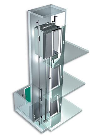
Basic configuration of an
in-ground hydraulic elevator
 |
 |
To lower the car, the elevator control system sends a signal to the valve. When the valve opens, the fluid that has collected in the cylinder can flow out into the fluid reservoir. The weight of the car and the cargo pushes down on the piston, which drives the fluid into the reservoir. The car gradually descends. To stop the car at a lower floor, the control system closes the valve again.
There are three types of hydraulic elevators, known as "in-ground," "holeless" or
"roped" systems.
An in-ground elevator requires a deep hole below the bottom landing because the cylinder goes down into the ground as far as the elevator travels up. Typical in-ground installations use a PVC casing to protect the cylinder from electrolytic and other corrosive chemical actions that could lead to future underground oil leaks.
Holeless elevators are typically used for buildings where it is not possible to drill a cylinder hole. They do not employ a conventional piston/casing arrangement and therefore do not require a hole to be dug for the hydraulic cylinder. In most designs the cab is lifted by a pair of hydraulic jacks, one on each side of the elevator. They are used if a limited amount of travel is required. Sometimes the hydraulic piston (plunger) consists of telescoping steel tubes that allow for increased travel.
Roped hydraulic elevators use a combination of hydraulics and a complex indirect attachment to the cab. Most applications are in existing buildings where drilling
a hole for jack assemblies is impractical or more travel is required than would be possible with a holeless
direct-acting elevator.
Â
Â
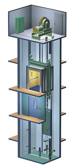
Basic configuration of a traction elevator
 |
 |
The advantages of the hydraulic elevator include:
- No overhead machine room is necessary
- Elevator hoistway dimensions are optimized
- Loads are distributed to load bearing walls-there are no overhead structural
requirements
- Machine rooms can be located remotely
- Installation costs are generally less than those for conventional traction roped systems
Â
The drawbacks of the hydraulic elevator include:
- Machine room needed for pump unit and control system
- Limited speed and performance
- High noise levels as compared to other systems
- Odor from heated oil
- Environmental concerns due to significant use of oil
- Poor ride quality as compared with other systems
Â
Traction Elevator
The most recognizable elevator design is that of the traction elevator. Ropes are attached to the elevator car and looped around a hoist machine with deep grooves in its circumference known as a sheave. The sheave grips the hoist ropes, so when the sheave, which is connected to an electric motor, rotates, the ropes move too. When the motor turns one way, the sheave raises the elevator; when the motor turns the other way, the sheave lowers the elevator.
In gearless elevators, which have traditionally been used for very tall buildings or to achieve exceptionally fast speeds, the motor rotates the sheaves directly, allowing speeds up to 3,000 fpm (35 mph).
In geared elevators, which have traditionally been used for mid-sized office and residential buildings, the motor turns a gear train that rotates the sheave. Mechanical limitations typically limit the speed to 450 fpm. Traditionally, the sheave, the motor and the control system are all housed in a machine room above the elevator shaft. From the building exterior, the machine room typically appears as a box on the rooftop. Other configurations can be utilized that eliminate the need for the overhead machine room by placing components at or near the first landing-a "basement" configuration-or elsewhere along the shaft (or hoistway).
The ropes that lift the car are also connected to a counterweight, which hangs on the opposite side of the sheave. The counterweight weighs about the same as the car filled to 40 percent capacity. In other words, when the car is 40 percent full, the counterweight and the car are perfectly balanced. With equal loads on each side of the sheave, it only takes minimal force to tip the balance one-way or the other.
Â
Â
2,500 lb Capacity
Application
|
|
Traditional Traction (geared)
|
EdMRL
(gearless) |
Speed (fpm) |
150 |
200 |
150-500 |
Motor size (kW/hp) |
40hp/30kW |
22hp |
8hp |
Typical current
values (amp) |
|
|
|
Nominal |
57 |
58 |
12 |
Starting |
114 |
105 |
14 |
Main fuse size (amp) |
70@480V |
80 |
15@480V |
Main fuse size (amp) |
28,000 |
30,600 |
8,600 |
Thermal losses (BTU) |
9,000 |
9,450 |
3,700 |
Oil requirement
(gallons) |
80 |
4 |
0 |
Control space noise level (dBA) |
70-80 |
65-70 |
50-55 |
|
Â
Â
Both the elevator car and the counterweight ride on guide rails, which run along the sides of the elevator shaft. The rails keep the car and counterweight from swaying back and forth, and they also work with the safety system to stop the car in an emergency.
Â
Â
The advantages of the traditional traction elevator include:
- Fast speeds and efficient performance
- Quiet, smooth ride
- Available for high-rise applications
The drawbacks of the traditional traction elevator include:
- Higher installation cost
- Significant structural loads at the top of the hoistway
- Elevator machine room required
Â
Machine Room-Less Elevator
Development of the MRL gearless traction machine came about as a result of technological innovations that significantly reduced the size of electric motors used with traction systems. In the mid 1990s, elevator designs began featuring a small permanent-magnet synchronous motor (PMSM) combined with a variable voltage, variable frequency (VVVF) drive. The change reduced the size, weight, heat output and energy consumption of traditional traction systems by up to one-half. The energy savings in comparison to hydraulic systems are even more substantial. The technology was incorporated into elevators with the result that, because of the reduced size of the new motor, a machine room above or adjacent to the elevator hoistway was not required. Instead of placing
the machine in a separate room, the motor mechanism could be mounted within the hoistway itself.
Â
Â
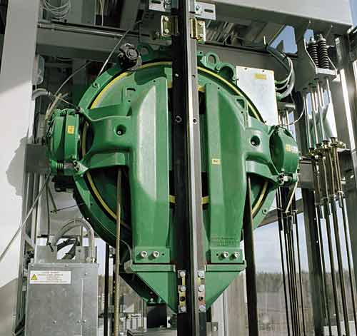 |
MRL machine mounted on rail in the hoistway.
Courtesy of KONE Inc. |
|
Â
This new technology created a cascade of environmental benefits. Not only did the new design lead to a reduced use of both oil and energy for starting and running the
elevator-plus the avoidance of potential ground contamination-it also led to more efficient and safe installation techniques and use of valuable interior space. Used abroad for many years, the MRL is the standard product for low to mid-rise buildings in Europe and Asia where the hydraulic system is almost extinct.
The United States has trailed the rest of the world in the adoption of the new Machine Room-Less elevator system. When it was first introduced, there was a slow acceptance rate because of code requirements, since national and local building codes did not address elevators without machine rooms.
In 1998, work started on addressing all safety aspects with regard to the Machine Room-Less elevator type of design. Seven years later, the American Society of Mechanical Engineers (ASME) issued a special supplement to its A17.1 Safety Code for Elevators and Escalators. That supplement, named A17.1S-2005, contained all of the pertinent safety elements related to issues involved with MRLs.
Earlier this year ASME incorporated that supplement into its latest edition, A17.1/CSA B44 - 2007 Safety Code for Elevators and Escalators. This 2007 edition covers Canada (elevator codes are now harmonized for all of North America) and covers the design, construction, operation, inspection, testing, maintenance, alteration, and repair of elevators. The American National Standards Institute (ANSI) has approved the ASME elevator code as a national standard.
Before the issuance of national standards, state and local code officials approved MRLs on an individual-case basis. Since then, many authorities have adopted the latest ASME code. With a growing number of MRL suppliers, national standards and increased adoption of national standards by local code bodies, the number of Machine Room-Less elevator installations in the United States is expected to increase dramatically.
Â
Saving Space
Perhaps the most significant feature of MRLs is that they offer architects and designers a lot more design freedom. Less space has to be dedicated to essentials like elevators and their machine rooms, so that more space is left over for productive uses. In addition, building designers have more freedom to create an aesthetically pleasing and operationally efficient building.
Driven by technologies and designs unique to each elevator company, manufacturers have adopted two basic configurations for the placement of the machine. In one configuration, the machine is located in the overhead space above the hoistway. The second configuration features a rail-mounted machine within the hoistway.
Â
Â
LEED® Certification: Using Machine Room-Less
Elevators Help With Green Certifications
|
Now under construction and scheduled for delivery in the fall of 2008, the new office building at 1050 K Street is located on one of the most sought after pieces of undeveloped land in downtown Washington, D.C. The 136,000 sq ft, 11-story office block with ground-level retail and parking below is designed to be LEED Gold Certified. The building has four 500-feet-per-minute Machine Room-Less elevators (MRLs), two on each side of the lobby.
Chuong Cao, project designer, and Jason Wright, project architect, with Hickok Cole Architects, Washington, D.C, explained that there were two basic reasons why MRLs were specified rather than traditional traction elevators. The first reason is the energy savings of MRLs. Since the building is expected to achieve LEED certification, it was very important to have systems that promote energy savings. In this way, energy-efficient elevators would contribute to the overall energy savings of the building and therefore add to the prerequisite and credit requirements of LEED.
The second reason concerns building height requirements and the value of penthouse square footage. In the city of Washington D.C., the building height limit is 130 feet. A penthouse may be added that does not exceed 18 feet, 6 inches in height. Typically, it's tough to design a penthouse floor with elevator service using a traction system, says Chuong, because it requires a height overrun on the penthouse floor to accommodate the elevator and, on top of that, additional height for the machine room. (The height of the machine room is included in the permissible additional 18 feet, 6 inches.)
Since MRLs are energy efficient and require no machine room, they were a logical choice for 1050 K, as the building is known. The controllers for each bank of elevators will be located in a closet next to the hoistway on the penthouse floor.
The owner is excited about the technology used by MRLs, reports Chuong. Even though it is not new, it is fairly new to the Washington area and not a lot of buildings have them. For this reason -and the fact that DC has not fully adopted the latest national ASME elevator code-it is taking some additional time for the authority that issues building permits to incorporate the new technology into its approval process, especially given the code requirement for access to the elevator machine room because there is no longer a true machine room.
The interior of the lobby is a gallery of photographs with one side finished in glass and the other side finished in wood. The two cab interiors on each side continue the finishes, so that when the elevator doors open, the entire walls on each side appear as glass or wood. In order to ensure that the weight of the finished cab interiors met requirements, the architects worked closely with the elevator manufacturer to determine which thickness of glass should be specified.
|
|
Â
Â
|
KONE is a world-leading manufacturer of sustainable, energy-efficient elevators, escalators and autowalks. KONE is a service company known worldwide as a technology leader with the most innovative products and service methods in the elevator and escalator industry.
kone.com |
|
Â
Â
 |
Designed by Hickok Cole Architects with four MRL elevators, 1050 K
in Washington, D.C., will be ready for occupancy in fall 2008.
Courtesy of KONE Inc. |
|
Â
Building Cost Savings
The elimination of the machine room leads to lower construction costs. In addition, the new MRL elevator technology uses smaller motors, which, in turn, downsizes the necessary power supply. This further lowers construction costs (and energy costs in building operations) and allows more space within the building for other purposes.
However, space is required for an integral or adjacent controller closet. The integral control closet is typically near the top landing next to the door opening. The adjacent control closet, a configuration often driven by local or state codes or a particular elevator manufacturer's design, is either placed in a small space next to the hoistway near the top landing or in a remote location.
Â
Â
Â
 |
A. Integral control space at top landing (typically standard)
B. Remote control space or room located remote from the hoistway
C. Integral control space located at alternative floor
Courtesy of KONE Inc. |
|
Â
Â
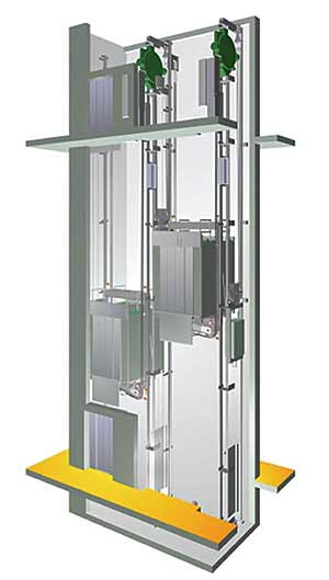 Basic configuration
of an MRL elevator
Basic configuration
of an MRL elevator |
|
|
Saves space |
May require case-by-case
approval by local code
authorities that have not
adopted the latest national
ASME elevator safety code |
No machine room required |
Core dimesions vary accoording to manufacturer |
Flexible placement of control closet |
Still relatively new in the U.S. |
Reduced motor size and weight |
Design of interior cab governed by limitations on cab weight |
Reduces energy consumption |
Installation requirements vary according to manufacturer |
Reduces heat output |
|
Eliminates oil |
|
Reduces project management interface |
|
|
Â
Energy Savings and Environmental Impacts
The new PMSM technology also means energy savings, which not only reduces building operations costs, but can positively impact the U.S. Green Building Council's LEED® Rating System calculations. PMSMs are 93 percent efficient or better, a favorable comparison to the typical 65 percent efficiency of traditional machines. The direct energy costs associated with elevator operation drop significantly with modern systems. The new gearless motors typically use 40 percent to 60 percent less energy than traditional traction or hydraulic motors. This can mean a savings of a few thousand kilowatt-hours per year for a single elevator, and up to tens of thousands of kilowatt-hours for multiple banks of elevators.
Also contributing to the energy efficiency of the MRL is the lower starting current required. The PMSM uses just 30 percent to 40 percent of the energy of comparable traction and hydraulic motors. Typically, an AC gearless low-rise elevator with a PMSM has less than a 10 horsepower (hp) motor, compared to motors of up to 40 hp for traction elevators and up to 60 hp for hydraulic motors.
Consider a 3,500-pound-capacity commercial elevator with seven landings and 60 feet of travel (or rise). A traditional geared machine uses an estimated 348,058 kWh of electricity in a single year, which, applying a rate of $0.072 per kWh, results in annual electrical costs of $25,060. A PMSM-driven elevator uses about 193,446 kWh of electricity per year. At the same utility rate, the estimated annual energy costs amount to $13,928-a savings of $11,132 or 44 percent per year. For the 30-year functional life of the building, savings would exceed $330,000.
Sustainable technology and design means much more than just saving energy. It includes eliminating or reducing risks of damaging the environment and reducing use of nonrenewable resources. MRL technology removes the need for a plunger and cylinder and thus eliminates the risk of accidental environmental contamination. Hydraulic elevators, on the other hand, employ oil-based fluids to move the elevator, which can leak and cause damage. (It should be noted, however, that current elevator code requires all buried plunger and cylinders to be protected from corrosion with a means to monitor the cylinder. As mentioned, this is typically achieved utilizing a PVC casing.)
Â
Â
Freestand Installation: Seeing The Moving Parts
|
A former furniture factory with exposed red cedar beams, the 5th Avenue Station in Naperville, IL, had been converted into restaurants, offices and residential space. The owner wanted a third elevator in an open space crossed by elevated walkways. Since there were few options for locating another elevator, Kathleen Mortensen, Property Manager of Fifth Avenue Station, chose to position it in a corner as a freestanding unit.
After investigating a hydraulic elevator-and voicing concerns about the potential for odor from the hydraulic fluid and the problem of finding space for a machine room-the property manager, with Prinmar Corporation, examined a machine room-less (MRL) model on another site. They found several advantages: Its electric motor was virtually soundless; there was no feeling of movement when riding inside the cab; and there was flexibility regarding the placement of the control room.
In keeping with the style of the renovated space, Guy Cummins − V.P. of Prinmar Corporation decided on a "retro high-tech" look. He enclosed the two front and back walls of the elevator in masonry, and encased the two side walls in glass so that the track and moving parts could be seen by the public, but not by elevator passengers.
Since there was a small amount of space at the top of the hoistway, Prinmar Corporation crowned the elevator by terminating the concrete walls there and adding four walls above in steel and glass. The elevator has become its own showpiece: With lights inside the hoistway, people standing on the second level can enjoy watching the moving machinery.
|
|
Â
Energy conservation is further achieved through other efficiencies. Elevator door operators are designed with more efficient permanent-magnet synchronous drive motors that require less power to operate than conventional door systems. These solutions feature a drive motor centered directly above door panels and a simplified torque transmission that eliminate complicated cam mechanisms.
Meanwhile, environmental considerations continue to impact future systems. Manufacturers worldwide are working toward developing more reliable designs for elevators that have a longer operating life and use less energy.
Â
Â
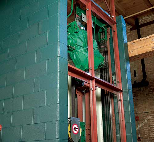 |
The Machine is highly visible mounted behind glass in the MRL designed by David Lindquist & Associates for 5th Avenue Station, Naperville, IL.
Courtesy of KONE Inc. |
|
Â
MRL Design Considerations
Faced with MRL patents held by competitors, manufacturers have developed different solutions for utilizing PMSM machines, suspending the cab, and locating the machine, controls and counterweight. The result is that building requirements can vary for different MRL product lines.
Architects should, therefore, consider the following when adding MRLs to existing structures or integrating MRLs in new construction:
- Different MRL manufacturer dimensions. During design and specification phases,
architects should be aware that manufacturers have different dimensions for shaft
footprints, pit size and overhead space. Designers are advised to plan for the worst-case
scenario and allow for maximum dimensions. This will also allow for multiple
competitive bids and manufacturer substitutions as needed.
- Interior cab design is governed by limitations on cab weight. This could impact
the architects' own custom design and choice of finishes for the interior cab. Because
MRL machines are smaller than traditional traction models, permissible cab weight is
less than with traditional traction machines. Cab weight is derived from calculations
involving speed, number of stops and varies according to application.
- Power usage impacts electrical requirements. Unlike a hydraulic elevator that may
require a 25 hp to 60 hp motor, an MRL elevator operates on a much smaller machine.
This will reduce the size of the main line feeder and emergency generators.
- Ventilating and cooling. Some integral MRL configurations place the controller in the
front wall at the top landing; in these cases a grate built into the back provides needed
ventilation. Others locate the controller in an adjacent closet, which may require that
ambient temperatures be maintained within manufacturer's guidelines.
- Controller location. As a general rule, the controller can be located within 100 wire
feet from the machine. This gives designers the flexibility of locating the controller as
needed within this range to free up valuable square footage or create a desired space
layout. Architects should be aware that placement of the control room should be
checked for local code compliance, as some authorities have yet to adopt the national
ASME code.
- Machine location and structural loading. Designers should know the location of the
MRL machine since it may impact the building's structural requirements.
One manufacturer mounts the machine on the guide rails, which, by transferring weight
down to the pit floor, creates no overhead structural loads. Another manufacturer
suspends the machine from one or more beams tied into the building in the
overhead area, which impacts structural calculations and could add to building
infrastructure costs.
- Construction coordination. The sequence of construction phases differs depending
upon the MRL manufacturer and can affect the construction schedule. In one case,
an MRL can be assembled from inside the hoistway once the shaft is built and capped.
In other instances, manufacturers require the cap be left off of the hoistway in order to
install the machine and its required beam arrangement by crane. It is typically
the responsibility of the general contractor to provide the use of a crane for
these applications.
- State and local code approval may be required. If the local code authority has not
adopted the national 2005 Supplement to ASME 17.1/CSA B44-2007 Safety Code for
Elevators and Escalators, approval on a case-by-case basis may be required. Further,
certain manufacturers provide alternative suspension systems to traditional steel ropes
that may require review by local code authorities.
Â
Â
MRL Installation Advantages
The costs of MRL installation in terms of both contractor time and materials are less than those associated with traditional elevators for the following reasons:
- MRL installations require fewer construction materials and less work time: No well
holes to be drilled; no pits to be waterproofed; no requirement for a structural machine-
room slab. Some product lines, it should be noted, do require beam attachments
(see "MRL Design Considerations," above).
- Some models may be installed from the ground up, thus eliminating the need
for scaffolding.
- Some MRL installations do not require a crane to hoist machine or control equipment to
the penthouse floor or to hoist a structural machine-room slab
as required for traction elevators. This increases safety and lessens the project-
management challenges inherent in some elevator designs. For instance, hydraulic
elevators may require a crane to place the plunger and cylinder in the well hole.
- Installation procedures for MRL technology are highly visible and therefore offer more
control over the work environment.
Maintenance
Some manufacturers suggest that maintenance contracts should depart from the traditional criteria that determine a maintenance schedule. Instead, they propose that new agreements use performance as the measuring stick. This allows the owner to create a customized maintenance agreement.
Many leading elevator consultants urge their clients to secure long term maintenance pricing when soliciting new equipment bids. This method of procurement will ensure a competitively priced maintenance program, as well as allow for a beneficial life-cycle cost.
Â
Â
 |
EOS twenty one, a residential complex in Alexandria, VA.
Courtesy of KONE Inc. |
|
Â
Â
Replacement: A Smooth Retrofit
|
The owner of EOS twenty one, a residential complex in Alexandria, VA, wanted a reliable, safe upgrade for a fleet of 40 year-old plus hydraulic elevators-plus an improvement to the value of the property and an increase to tenant's satisfaction. Updates to the 16 elevator systems needed to accommodate the existing hoistway structure, while improving performance, safety and aesthetics.
David Mirch, principal of the elevator consultants DMT LLC, in Boonsboro, MD, learned that the entire MRL system could be installed within the existing hydraulic hoistway. The manufacturer arranged site visits for Mirch and the owner's representative to buildings with MRL elevators currently installed, so they could see for themselves how the system functions. They learned that the MRL delivered improved leveling, which means more accurate stops. Energy savings, also, were a huge factor in the decision to choose MRLs.
The hoistways were gutted and the well holes which contained the cylinders that housed the pistons, were removed and then sealed.
New rails were installed in the hoistway to support the entire elevator structure including the drive machine. Unlike other MRLs the old machine room located at the bottom of the hoistway was used to house the new controller.
|
|
Â
Â
Karin Tetlow writes frequently about architecture and construction.
Â