Understanding Seismic and Wind Restraints


Consequential Damage
Piping and systems or equipment that could normally have a component importance factor of 1.0, but which are suspended above life safety or essential systems such as fire protection sprinkler piping, must be shielded from the higher importance system or be redesignated as having a component importance factor of 1.5 and be restrained accordingly.
 |
Typical no-hub type coupling Image courtesy of Kinetics Noise Control |
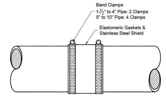
Drain, Waste and Vent Pipe
Waste, drain, and vent lines typically do not hold pressure; nor do they run completely full all the time. They are mostly manufactured from materials such as cast iron, steel, or PVC plastic that are brittle and have low deformability. They are traditionally connected by slip hub-type type fittings. Hub-type pipes have a hub on one end with an I. D. that is just slightly larger than the O. D. of the pipe. Therefore, extra care must be used when restraining them.
Heavy-duty no-hub pipe couplings should be used for seismic applications, where no-hub pipes are joined together with a flexible coupling that slips over the O. D. of the pipes and is clamped with band clamps.
Wind Restraint Requirements
Any component of piece of equipment that is exposed in any way to the effects of wind should be restrained. There are no exemptions for exposed components.
Codes Relating to Wind Restraint
The relevant portions of the codes include:
2006/2009 IBC Section 1609.1: “Buildings, structures and parts thereof shall be designed to withstand the minimum wind loads prescribed herein. Decreases in wind loads shall not be made for the effect of shielding by other structures.”
2006/2009 IBC Section 1609.1.1: Wind loads on every building or structure shall be determined in accordance with ASCE 7-Chapter 6, which describes procedures for determining design wind loads.
2006/2009 IBC Horizontal Design Wind Load is defined by ASCE7-05 Sections 6.5.15 & 6.5.15.1, and is roughly twice that specified in 2003 IBC.
2006/2009 IBC Design Wind Uplift Load is recommended by ASCE 7-05 Section C6.5.11 (page 300). It is a function of the location of the equipment on a roof with the corner areas being most severe. For estimating purposes it can be estimated as slightly greater than half the horizontal design load.
 |
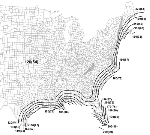 |
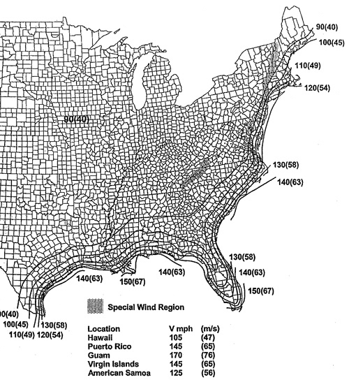
Current wind restraint requirements are based on 2006/2009 IBC Basic Wind Speeds. Future requirements in 2012 IBC will be more rigorous. Source: ASCE 7-05, figure 1 |
Notice


