Understanding Seismic and Wind Restraints


The entire A/E team is responsible for seismic restraint. The building structure must be able to handle the expected seismic loads generated by the MEP components, which, in turn must be restrained.
Selecting Restraints
Selecting restraints is most easily (and generally) performed by the manufacturer of seismic restraints. In order for manufacturers to select appropriate restraint components, design professionals should provide the following information:
* Listed on the first sheet of structural drawings:
1. Applicable building code, or codes
2. Seismic design category
1. SS or SDS short period acceleration.
2. Site class soil type
Noted on the specifications:
The seismic portion will alert the manufacturer's designer to any special considerations. of the restraint system.
Information for piping
- The component importance factor
- Piping layout with pipe sizes, connections and materials.
- Whether the piping is for domestic hot water, domestic cold water, medical gas, natural gas, vacuum, drain, waste or vent.
- Identification of any piping runs that are to be trapeze supported.
Information for equipment
- The component importance factor
- Cut sheets with complete dimensions and, if applicable, mounting locations.
- Operating weight and center of gravity of the equipment.
- The building height and where the equipment actually attaches to the building.
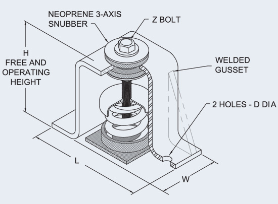
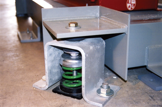
| Typical Seismic and Wind Restraint for HVAC Equipment | |||
Post-type three-axis coiled spring isolator and seismic and wind restraint may be used for indoor and outdoor floor mounted fans, pumps, air compressors and other mechanical equipment. It provides all-directional restraint with vertical limit stops. Motion during an earthquake, which would otherwise displace life support and emergency equipment is limited to 0.25-in. in all directions. The steel housing assembly limits both lateral and vertical movement of the supported equipment without degrading the vibration isolation of the spring during normal equipment operating conditions. Properly selected, this type of isolator provides adequate restraint against code-based seismic and wind forces required by code. |
Anchorage of MEP Components
The purpose of a seismic restraint is to form a load path between the MEP component and the building structure. It must be attached to a portion of the building structure that is capable of carrying the expected seismic loads.
Research has shown that the force generated in a building increases as one rises through the structure. Surprisingly, the total height of the structure is not as important a factor as is the location of equipment in that structure relative to the roof. The IBC Code addresses this condition by requiring that the design used when specifying equipment anchorage includes forces that increase by a factor of three as equipment locations move upward from grade to the roof.
Notice