From Mortar Snots to Perpends: The Basics of Through-Wall Flashing


Design Principles
There are several important factors to consider when designing a flashing system for high performance buildings. Design professionals should consider specifying through-wall flashing that has the following attributes. The flashing should be constructed of a high performance membrane that is long lasting, compatible to sealants and UV stable. Although the cheapest flashing, PVC is not a recommended material for long lasting flashing.
Through-wall flashings rarely leak through the membrane however, they can be damaged during installation. To prevent puncture, a durable high performance membrane similar to high end roofing membranes should be specified. All membrane flashing comes to the job site in rolls, and all manufacturers have accessories that are used to join the pieces together correctly.
Flashing systems should incorporate preformed shapes or “cloaks” which a mason can easily install. Most leaks occur at areas that require special detailing. Using a preformed shape will allow the mason to be responsible for only the watertight laps around what might otherwise be a difficult flashing detail. Cloaks eliminate the need for the cutting and pasting required with other flashing membranes. The basic design principle is to understand the basics of water migration and design an integrated moisture barrier and drainage plane throughout the entire wall cavity.
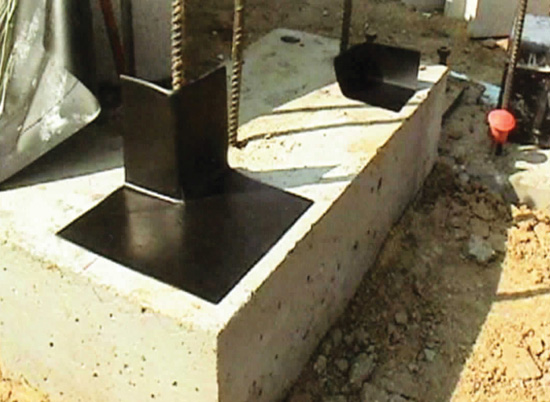
Photo courtesy of Hyload Inc.
A preformed flashing shape or cloak assures easy transitions at this termination point. This image demonstrates the installation of an outside corner and a 6-inch end dam. The 6-inch end dam will terminate the flashing at a doorway.
Flashing Placement
Through-wall flashing should be placed at grade, above, and below any wall openings, at the top of all masonry walls and any location where the downward flow of water is interrupted. A complete flashing system includes not only the flashing, but also the protective waterproofing membranes that overlap flashing materials as well as the knowledge as to where that membrane is placed based on the humidity levels of the project as seen in the case study for the National Museum For The American Indian.
It is important that the flashing is installed to a suitable substrate. The flashing should be installed to a solid surface that is dry, smooth and free from protrusions. As preservation architect, Randy Case, AIA, LEED AP, principal of Architecture + Design in Battle Creek, Michigan has discovered that “Many older buildings were constructed without proper through-wall flashings, or details, and correcting those conditions can be a challenge when meeting the Secretary of Interiors Standards for rehabilitation and guidelines. Be sure to engage the State Historic Preservation office when designing flashing systems that are being proposed to correct original design flaws when they are going to effect the physical appearance of an historic property.”
At Grade
Beginning at the lowest point of a building, flashing at grade can be built into a block back-up wall, brought across the cavity and through the veneer to form a drip edge. Reviewing the materials of the flashing with the manufacturer is critical to assure that the selected flashing material will not “fishmouth” or create a wave along the drip edge. Through-wall flashing is attached to the back-up walls and then brought through the veneer 4 to 6 inches above grade so water can drain out through the weep system.
Since grade is not always level; step flashing will require careful detailing. Step flashing is placed at each different course of masonry maintaining a constant 4 – 6 inches level above grade to capture any moisture that is running down the backside of the brick. At each change in level, the through-wall flashing is turned up to form end dams and two weeps per flashing course. Two weeps per flashing course should also be provided. Some specifications call for the through-wall flashing to be left exposed by as much as 2 – 3 inches until the architect directs the contractor to trim it off. The advantage of this specification it to assure that the through-wall flashing is not installed a half-inch back from the face of the building at a juncture where it is critical.
Above and Below Wall Openings
Through-wall flashing is installed above and below any wall opening. Windows, doors, and ventilation systems all require flashing that is turned up on three sides so that water is directed out the weep system. A typical two dimensional detail provided to the contractor shows the location of the flashing course, but unless the image is projected in three dimensions, the detail doesn't show the end dams that capture the water to remove it from the building.
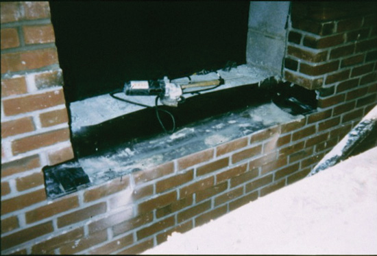
Photo courtesy of Hyload Inc.
Correct flashing detail at a window opening showing end dams.
Notice