From Mortar Snots to Perpends: The Basics of Through-Wall Flashing


Moisture, Perpends and Mortar Snots
Building scientists state that all of the forms of water: solid, liquid, vapor and adsorbed are culprits in how water enters a brick wall cavity. Once in the building wall system: “Water always changes its behavior, because its form is never constant. Evaporation, condensation, capillary suction, gravitational flow, vapor diffusion and mass flow of moist air are all happening at the same time inside building cavities and inside materials.”2 With a good understanding of the principles of water migration, a building science investigator can analyze the solution to most problems caused by poor wall construction.
Most moisture enters a wall cavity through a badly filled perpend. Derived from old English, perpends are head or vertical mortar joints between bricks. Head joints are more difficult to fill than the horizontal bed joints on a brick wall and the perpend must be buttered properly to prevent openings through to the backside of a wall system. Unfortunately, water runs through the path of least resistance and will find even the smallest opening in mortar a means to enter an interior wall cavity. If the cavity is blocked with excess mortar droppings, these “mortar snots” allow the wall to become a reservoir for water to pool and breed bacteria.
Another bridge that can block the interior cavity of a wall is an inward sloping, metal wall tie. Metal ties can collect mortar snots and contribute to moisture blockage. In worse cases, mortar droppings have filled cavity walls above flashing materials forcing water over the top of even the best laid through-wall flashing systems.
To help decrease the amount of mortar droppings, specify that the mason slope the backside of the mortar bed so that there is less mortar extruding as he lays the bricks. The Brick Industry Association also asks for a minimum of 2-inch clear space for the cavity wall to be constructed correctly.
Damproofing Course
The British refer to through-wall flashing as a damproofing course or DPC. When considering moisture penetration into a wall, all of the sides of the wall are important, top, bottom, inside and outside. There are different treatments for flashing at all of these four sides of a masonry wall. The top of a masonry wall is covered by a coping system designed to keep water from entering the top of the wall. The obvious source of moisture into wall cavities is from wind driven rain. Wind driven rain can cause both vertical and horizontal penetrations into a wall cavity. In some areas of a building, rising ground water and/or moisture will travel from below grade up into a wall.
A hidden source of moisture damage and one of the most common culprits is the migration of water vapor traveling through the wall assembly. Water vapor at the dew point is transformed into water. Water can fill a badly designed wall assembly to cause moisture damage if it is not properly drained back to the exterior with a damproofing course or through-wall flashing. Often, through-wall flashing may have the proper details but improper installation and/or attachments to the back-up wall. This causes water to go around the flashing material. In some cases, flashing manufacturers compound the problems by recommending that flashing be held back a half inch from the face of the brick without the caveat that this detail requires the additional step of adding a drip edge.
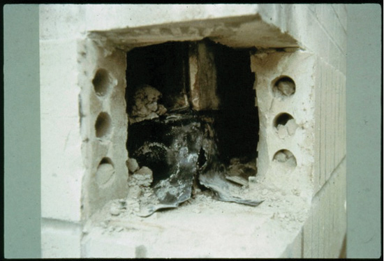
Photo courtesy of Hyload Inc.
Flashing held back from face of brick without the addition of a metal drip edge can cause moisture to migrate around the flashing and back into the wall cavity.
In an article by David Nicastro, P.E., from the March 1996 Construction Specifier “Magazine Masonry cavity walls – flashing not extended to face of wall”3 provides a good example of this type of flashing failure. Nicastro, a building science investigator was contacted because water was getting through the walls although every detail appeared to be correct. His evaluation of the through-wall flashing system determined that the flashing material was in good condition and it was attached to or built into the backup wall correctly. There were good details at the corners, but water was still getting into the building. He concluded that water was entering the building by going around the flashing. The flashing had been held back a half inch from the face of the brick and there was not an additional drip edge to complete the flashing system. The Brick Industry Technical Notes 21B Drip Edge/Flashing Extension provides the correct solution to this problem.4
Notice