This CE Center article is no longer eligible for receiving credits.
Thermal Performance
Thermal performance of a building, meaning the ability to retain or restrict the flow of heat between inside and outside, is the topic most people associate with the IECC when it comes to building envelopes. As discussed above, there are certainly other considerations, but thermal performance remains a key requirement of wood-framed construction and is treated in significant detail in the building envelope portion of the IECC for both residential and commercial buildings.
Here too, the key definitions are found in the IECC (IECC 202), including:
• Building Thermal Envelope: The basement walls, exterior walls, floor, roof, and any other building elements that enclose conditioned space or provide a boundary between conditioned space and exempt or unconditioned space.
• Continuous Insulation (ci): Insulating material that is continuous across all structural members without thermal bridges other than fasteners and service openings. It is installed on the interior or exterior, or is integral to any opaque surface, of the building envelope.
• U-Factor (Thermal Transmittance): The coefficient of heat transmission (air to air) through a building component or assembly, equal to the time rate of heat flow per unit area and unit temperature difference between the warm side and cold side air films (Btu/h · ft2 · °F) [W/(m2 · K)].
• R-Value (Thermal Resistance): The inverse of the time rate of heat flow through a body from one of its bounding surfaces to the other surface for a unit temperature difference between the two surfaces, under steady state conditions, per unit area (h · ft2 · °F/Btu) [(m2 · K)/W].
Code compliance on thermal performance begins with identifying the climate zone for the building project. The building type (commercial or residential) then comes into play, and the IECC uses charts and tables to identify the minimum performance requirements for the entire building thermal envelope. In many climate zones, it is no longer enough to simply provide insulation materials between the wood-framing members, since the wood framing itself has been demonstrated to compromise the effectiveness of the insulation. Rather, many wall and roof assemblies also require continuous insulation under the code to reduce the effects of “thermal bridges,” which allow heat to conduct through the wood framing (IECC C402 and R402). Traditionally, the insulation has been applied to the exterior side of the wall on one side or the other of the sheathing. The intent is to cover all wall framing, floor framing, etc. with a layer of insulation that is continuous around the entire building thermal envelope. In most climate zones where this applies, one or two inches of rigid insulation (R-5 or R-10) is called for. It is important to note that making it continuous around the full envelope requires some attention to detail, such that the interface of the wall continuous insulation meets and extends with continuous insulation in the roof and floor or basement insulation.
Recognizing the need for integration of the continuous insulation with the rest of the components, one manufacturer has introduced a sheathing panel with multiple layers integrated during the manufacturing process. These layers include a fused WRB that also acts as an air barrier on the face of the structural sheathing and adhered foam insulation on the back of the panel. This provides a nailable wood base for attaching exterior cladding, while providing the needed air and water resistive barriers on the exterior.
It is also worth noting that the IECC allows two ways to calculate the thermal performance of a building, whether residential or commercial. The simple choice is to select insulating products that are labeled to show minimum R-values that are equal to or greater than the code-required R-values prescribed for a particular building type in a particular climate zone. These tables take into account standard wood-framed construction and adjust the R-values appropriately recognizing that the performance of the total wall or roof assembly will be somewhat less. The alternative approach is to calculate the U-factor of the assembly using recognized and standardized methods. This method is more precise for specific construction assemblies and is generally used when some details of non-conventional construction may be employed.
Installing insulation between framing members during construction is commonly done after all mechanical and electrical rough-in work is finished and just prior to the installation of interior gypsum board or other finishes. If continuous insulation is installed on the interior surface, then it would be applied at this time too, although it does create some coordination and finish issues to have an extra inch or two of material extending into a living space. That is part of the reason continuous insulation is installed on the outside of studs at the same time as structural sheathing. If one insulation contractor is to install both types of insulation, then they are likely making multiple job-site visits and needing to coordinate with the framers and other subcontractors that may be applying WRBs, air barriers, and siding.

Photo used with permission of Huber Engineered Woods LLC ©2012
One way to add R-value to wall assemblies is to use single-panel sheathing systems with a built-in layer of continuous foam insulation integral to the back of the panel.
There are structural sheathing products available, however, that combine with rigid, continuous insulation, such that one panel provides both insulation and structural sheathing in one application. This saves installation time, reduces the amount of coordination required, and improves on-site quality control—applicable to the entire building thermal envelope including exterior walls.
Conclusion
We have seen how building codes and energy codes separately address the much related five performance issues of structural integrity, water resistance, vapor control, air tightness, and thermal performance. We have also reviewed some of the requirements and options available in terms of products and materials that can meet the various code requirements. Notably, the construction-products industry, in general, is seeking to provide architects, builders, and contractors with systems that can meet more than one of these five needs. In fact, at least one manufacturer provides structural sheathing with a layer of continuous insulation on one side and a pre-installed surface on the other that meets the requirements for both a water-resistive barrier and an air barrier. The use of continuous adhesive tape in the field plus related flashing provides the continuity and integrity of the system needed to meet code requirements. Ultimately, systems such as this go beyond meeting only code requirements and also provide a faster installation with increased quality control, single-source responsibility for warranty, ease of inspections, and long-term durability for building owners. Understanding all of the options available and the impact on installation, cost, and efficiency are critical to not only the initial code compliance of an exterior wood-framed wall, but also its long-term performance.

|
Huber Engineered Woods
Huber Engineered Woods, a manufacturer of innovative product solutions for the building industry, offers high performing products including AdvanTech® flooring and ZIP System® sheathing. Changing construction for your benefit.
http://www.huberarchitectlibrary.com/
|
Wood-framed construction has been, and continues to be, a very popular construction choice for single-family residential, multi-family residential, and light commercial buildings. Building codes and energy codes recognize this popularity and have incorporated requirements that apply specifically to wood-framed buildings. These codes have evolved in recent years with an increasing emphasis on building envelope performance related to five key areas—namely structural integrity, water resistance, air tightness, vapor control, and thermal resistance. The common design and construction response has been to find available products and materials that can address each of these five needs independently. This approach requires multiple layers of materials acquired from different manufacturers with separate installation steps for each. However, manufacturers have also begun to offer products that can combine multiple performance requirements into a single manufactured product or system. Design and construction professionals have come to understand that these integrated products can provide greater on-site quality control while providing a faster, more labor-efficient means to meet code requirements.

Photo used with permission of Huber Engineered Woods LLC ©2013
Evolving codes increasingly emphasize building envelope performance. Structural products offering integrated layers of protection against moisture, air leakage, and thermal bridging are now available to add quality control on-site, while meeting multiple requirements.
Applicable Codes
Historically, as is true today, the applicability of a particular code or specific requirements starts first with a determination of the basic building type. This is essentially determined by the way the building is used or occupied and to some extent on the size or construction type. Residential buildings are treated differently than commercial buildings under the codes, and high-rise buildings are treated differently than low-rise buildings. While the categories of code requirements are similar between these different types (i.e., fire safety, light and ventilation, energy usage, etc.), differences exist in the minimum or threshold levels of performance among the different building possibilities.
The International Code Council (ICC) is an association of government, corporate, and individual members who together form the largest building and safety code organization dedicated to protecting the property, health, and safety of people worldwide. It is dedicated to developing model codes and standards used in the design, build, and compliance process to construct safe, sustainable, affordable, and resilient structures.
Most U.S. communities and many global ones have adopted some or all of the family of International Codes (I-Codes) published by ICC. These I-Codes are a complete set of comprehensive, coordinated codes that address general building construction, fire safety, mechanical systems, electrical work, energy efficiency, and related issues. Together, they provide a common platform and format for a coordinated approach to create regulatory requirements for the construction and maintenance of buildings. Because of their widespread use, I-Codes will be the basis for the discussions in this article, recognizing that application of these codes vary across the county due to publication year and adoption rates. Further, specific building types will be linked to specific codes as follows.
One- and Two-Family Homes
Single-family or duplex homes, whether free-standing or attached as townhouses no more than three stories above grade, are specifically covered under the International Residential Code (IRC) for One- and Two-Family Dwellings. This category of buildings is fairly easy to define, and the distinctions between them and other types of buildings are reasonably well understood, so it is not surprising that there is a separate treatment for energy efficiency in one- and two-family homes compared to other buildings. The International Energy Conservation Code (IECC) is the document that addresses such energy efficiency with two separate and distinct parts—one for commercial construction and one for residential construction.
Other Residential Units
Since people can occupy residential living units that are not one- and two-family dwellings, those occupancies are treated under the more general International Building Code (IBC). Specifically, the IBC identifies four categories of Residential Occupancies in Section 310: R-1 for transient residents (hotels, boarding houses, etc.); R-2 for permanent residents (apartments, dormitories, vacation properties, etc.); R-4 for between five and 16 permanent residents in a supervised residential environment; and R-3 for building conditions not otherwise meeting the definition of R-1, R-2, or R-4. One thing to be attentive to: while all of these building types are commonly considered commercial buildings for residential use, the IECC doesn’t make distinctions the same way. Rather, for purposes of the IECC, a residential building includes not only detached one- and two-family dwellings (including townhouses), but also any Group R-2, R-3, or R-4 building that is three stories or less above grade. The significance of this distinction is that the residential provisions of the IECC are more stringent than the commercial ones in terms of the building envelope. Hence, while all R-1 buildings and any R-2, R-3, or R-4 buildings over three stories can use the commercial portions of the IECC, those other than R-1 at three stories or below need to comply with the residential portions of the IECC.
Non-residential Buildings
All buildings that don’t fall into the scope of the IRC come under the provisions of the IBC for new construction. Existing buildings that are being repaired, altered, or added on may be subject to the International Existing Building Code (IEBC), which allows for some accommodation of existing conditions provided all new work complies with the IBC. Both of these codes require compliance with the commercial portions of the IECC, and both indicate when wood-frame (Type 5) construction is allowed or not.
With an understanding of the differing applicability of the I-Codes on various building types that can use wood-framed building envelopes, let’s turn our focus to five specific characteristics required by the provisions of these applicable codes.

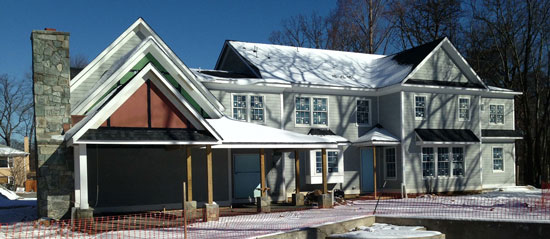
Photo used with permission of Huber Engineered Woods LLC ©2014
Wood-framed construction has been and continues to be a popular construction choice for single-family, multi-family and light commercial buildings. Codes continue to evolve to address structural performance, moisture, air, and thermal management in the critical exterior wall assembly area.
Structural Framing and Sheathing
The first and most common purpose of wood framing is to provide the structural support for the building. Several chapters in the IRC have very specific tables and charts indicating the required sizes of framing members for floors, walls, and roof-ceiling construction. These tables break down the allowable spans for different types of wood species at different spacings (16 inches, 24 inches on center, etc.). While this information is important and valuable for both the engineering of a wood-framed structure and identifying code compliance, there is more to the structural requirements than the framing.

Photo used with permission of Huber Engineered Woods LLC ©2013
The applicability of a code or its specific requirements starts first with a determination of the building type based on the way the building is used, its occupancy, size, or construction type.
Structural engineering principles and the IRC recognize that if a wood-framed wall is not properly braced, it will move, warp, and potentially fail. This is true not only of a particular wall, but of the entire building as well. Dramatic failures of this type can be found in news coverage of storms or floods, where a wood-framed residence is seen slanted to one side or even collapsed with a pitched roof still intact above. The wall bracing in these cases was subjected to wind or other forces that exceeded the capacity of the bracing. As such, the IRC and the IBC require that exterior walls be designed not only to provide for the direct vertical loads imposed on them, but also for the other horizontal or shear loads that can be imposed by outside forces.
There are multiple methods for providing the needed wall bracing as recognized and allowed for by the building codes. The historical approach was to use “let-in” corner bracing, which was rather labor intensive and required a series of studs to be notched at an angle to receive a one-by-four member recessed to be flush with the face of the studs. Although the IRC still recognizes that approach, the availability of structural wall panels made from plywood, structural particle board, oriented strand board (OSB), or other acceptable engineered products are much more popular and common. The reasons are obvious, in that a continuous layer of structural sheathing provides a more consistent, rigid, wall bracing system that is quicker and more economical to install. It also provides a continuous, fairly smooth surface for other layers of material to be applied. Hence, the codes recognize a series of different materials that can be used for continuous or intermittent bracing of exterior wood-framed walls.
Because there are variables between buildings and their locations, the codes call for a bit more detail in the selection of wall bracing material. Specifically, the code identifies zones or locations where bracing is required as a minimum structural requirement. It goes on to identify nailing or fastening patterns and spacings, taking into account the spacing of wood framing members. It further indicates the minimum thickness of selected materials since more thickness essentially equates to more strength. There are also tables and criteria for addressing seismic and wind loads of different degrees, which directly impact the structural requirements of structural sheathing that acts as bracing.
Roof construction follows a similar set of requirements. The IRC identifies allowable spans for rafters based on varying structural criteria and also recognizes the use of pre-engineered roof trusses. But, it also goes on to identify the minimum requirements for wood structural panel sheathing used over the rafters or roof trusses. Attachment, span, thickness, and other traits of the structural sheathing are all identified based on reference to the appropriate tables. The additional variable is the presence or absence of snow loads to various degrees, which must be taken into account for the sheathing, just as it is for the framing members. Hence, the sheathing thickness comes into play based on the anticipated loading and the spacing of the framing beneath it.
Whether used for wall or roof construction, it is important to recognize that there is a wide variety in available sheathing products, and not all of them carry sufficient structural strength to be used everywhere. Inadequate strength may not lead to dramatic and sudden failure, but it could likely lead to sagging and deterioration not only of the structure, but of other building components and systems as well. The American Plywood Association (APA) has published a voluntary product standard known as PS 2-10: Performance Standard for Wood-Based Structural-Use Panels. This is the document that forms the basis for the definition, testing criteria and certification of different types of wood panels, including sheathing, structural sheathing, and combination subfloor underlayment applications. For sheathing, it defines the general minimum requirements for use in construction applications, such as a covering material for exterior walls and roofs when fastened to supports spaced in accordance with the span rating of the wood panel. It also defines a Structural 1 Sheathing, which must meet all of the requirements for common sheathing plus additional requirements identified in the Performance Standard for “cross-panel strength and stiffness and for racking load performance.” This higher performance has a greater capacity for use in braced shear wall designs, making it appropriate to resist high winds and other forces. Prudent designers will tend to routinely specify Structural 1 panels to eliminate any guesswork for safety and structural integrity. Fortunately, some manufacturers seek that certification as a matter of routine for their products, recognizing that it is a designation that makes for a better product and a better building in the end.

Photo used with permission of Huber Engineered Woods LLC ©2011
Inadequate strength may not lead to dramatic failure, but it could lead to a compromised structure. There is more to structural requirements than framing.
Water Resistive Barrier (WRB) and Drainage
With an appropriate structure in place, the building codes—both the IBC and the IRC—are concerned with the long term durability of that structure. As such, they include requirements related to protection from weather and, specifically, water that can penetrate an assembly and cause deterioration or damage to the wood. In this regard, the codes offer some specific definitions of items that need to be understood: (IBC 202, IRC R202)
- Water-Resistive Barrier (WRB): A material behind an exterior wall covering that is intended to resist liquid water that has penetrated behind the exterior covering from further intruding into the exterior wall assembly.
- Exterior Wall Covering: A material or assembly of materials applied on the exterior side of exterior walls for the purpose of providing a weather-resisting barrier, insulation, or for aesthetics, including, but not limited to, veneers, siding, exterior insulation and finish systems, architectural trim, and embellishments such as cornices, soffits, and fascias.
- Exterior Wall Envelope: A system or assembly of exterior wall components, including exterior wall finish materials, that provides protection of the building structural members, including framing and sheathing materials, and conditioned interior space, from the detrimental effects of the exterior environment.
Chapter 14 of the IBC describes the particulars for exterior walls, including mandatory performance requirements (IBC 1403). Chapter 7 of the IRC has similar requirements (IRC R703.1.1). In clear and certain terms, the codes state that “[e]xterior walls shall provide the building with a weather-resistant exterior wall envelope.” It goes on to require that “[t]he exterior wall envelope shall include flashing...(and) shall be designed and constructed in such a manner as to prevent the accumulation of water within the wall assembly by providing a water-resistive barrier behind the exterior veneer...and a means for draining water that enters the assembly to the exterior.” Keeping in mind that this is all about the general integrity of the exterior wall, the clear intent is to avoid damage to the wall from water and weather by requiring the use of flashing, a water-resistive barrier, and drainage for any water that does penetrate.
The IBC and IRC identify two options for WRB materials, first stating: “A minimum of one layer of No.15 asphalt felt, complying with ASTM D 226 for Type 1 felt...” (IBC 1404.2, IRC R703.2). Asphalt felt has certainly been a traditional material for many thermal envelope installations, including walls and roofs; however, it is seen as a rather obsolete material compared to other modern alternatives. Fortunately, the second IBC and IRC option is to allow “other approved materials,” which refers to “materials that are acceptable to the building official or authority having jurisdiction” rather than a long list of alternatives.
Section 1703 of the IBC provides the building official with the means to request independent information on other materials in order to issue such an approval.
One of the most common means to identify a material that can readily be approved is for a manufacturer to apply for an Evaluation Service Report (ESR) prepared by ICC Evaluation Services (ICC-ES), a nonprofit, third-party certification subsidiary of the ICC. Data submitted for specific products must come from an accredited testing agency or laboratory to be considered. ICC-ES then conducts thorough evaluations of that independent data to determine whether a product complies with the appropriate code provisions or safety measures as claimed. If successful, an ESR is written that lets code officials know that a product meets the applicable building code and is safe for installation in construction. The distinction between this process and simply supplying testing data to a code official lies in the fact that ICC-ES provides a continuing process. They perform ongoing audits to ensure that products meet quality-control standards and continue to comply with the findings of the original evaluation. The whole process is accredited by the American National Standards Institute (ANSI), and is set up to truly and completely comply with Section 1703 of the IBC, which the code official is relying upon.
Other approved materials used to meet the WRB requirements currently include a variety of forms. Some are self-adhered sheet membranes (sometimes called “peel-and-stick” materials) that have traditionally been used in roofing applications and were also popular on below-grade walls. There are also spray-on systems that are formulated to be applied in thin or thick applications depending on the product and its makeup. Additionally, there are other types of sheet goods and systems that each have their own requirements for installation. Note that there are a variety of manufacturers and products, such that performance can vary considerably based not only on the product, but also on the quality control of installing them in the field. Seams and joints are particularly important in this regard and can be a significant source of problems later on if not treated correctly—compromising the reason for the WRB in the first place.
In designing a wall assembly, it is important to be aware that there are materials available that offer an integrated product approach, such that a sheathing product can have a WRB surface already adhered to it. This eliminates the need to identify a separate product and saves a step during installation, lowering labor costs. Such products offering an all-in-one systems approach often use a continuous tape as part of their system to seal all joints and corners and keep water from penetrating anywhere into the rest of the wall assembly. They also use a coordinated flashing system to seal any penetrations and allow water to drain away from the structure.

Photo used with permission of Huber Engineered Woods LLC ©2012
The IBC and IRC codes require a water-resistive barrier behind the exterior veneer and a means for draining water that enters the assembly to the exterior.
The second half of the requirement of a WRB is to provide “a means for draining water that enters the assembly to the exterior.” This means that any water that penetrates the outer cladding must be able to drain away and avoid potential damage of the wall. The means to do this is typically an irregular surface, channels, weep holes, etc. that create enough of a gap between the WRB and the cladding to allow for drainage. The industry standard for the effectiveness of such code-required drainage is currently ASTM 2273: Standard Test Method for Determining the Drainage Efficiency of Exterior Insulation and Finish Systems (EIFS) Clad Wall Assemblies. While there is a focus on EIFS, the testing procedure and outcomes have been accepted for other clad wall assemblies as well. A WRB material or surface that can also demonstrate efficiency according to this ASTM standard is generally considered to comply with the code requirements of the code as well.
Vapor Retarder
With structural support in place and a barrier to protect the interior from the exterior, another moisture-related concern must be addressed within the wall cavity. The IBC and IRC recognize that water vapor or air-borne moisture is different from bulk water. Nonetheless, the potential for damage to a wood structure is just as significant from vapor condensing in an exterior wall and deteriorating construction materials through rot, rust, or mold. Therefore, the IBC and IRC require protection against condensation in the exterior wall assembly and go on to clearly require a specific solution to provide that protection: “Class I or II vapor retarders shall be provided on the interior side of frame walls in Climate Zones 5, 6, 7, 8, and Marine 4,” (IBC 1405.3, IRC R702.7). The climate zones referred to here can be identified by a map and listing in the International Energy Conservation Code (IECC). There are eight such climate zones identified, with zone 1 being the most southern and warmest ranging up to the most northern and coldest in zone 8. Although the determination for applicability of the vapor retarder is determined by the IECC Climate Zones, the requirement for its inclusion remains in the IBC/IRC.
The class of vapor retarder referred to is based on the same definitions found in both the IBC and the IRC (IBC 202, IRC R202). The IRC adds some specific language to deem acceptance of different materials as meeting the different class ratings (shown in parentheses after each class below per IRC R702.7.2).
- Vapor Retarder Class: A measure of a material or assembly’s ability to limit the amount of moisture that passes through that material or assembly. Vapor retarder class shall be defined using the desiccant method of ASTM E 96 as follows:
- Class I: 0.1 perm or less. (Sheet polyethylene, unperforated aluminum foil)
- Class II: 0.1 perm - ≤ 1.0 perm. (Kraft-faced fiberglass batts)
- Class III: 1.0 perm - ≤ 10 perm. (Latex or enamel paint)
In the climate zones where the vapor retarder is required, it is called for on the “interior side of frame walls,” typically meaning on or behind the finished interior surface of the wall.
Air Barrier
A 2005 study sponsored by the National Institute of Standards and Technology (NIST) titled Investigation of the Impact of Commercial Building Envelope Airtightness on HVAC Energy Use (NISTIR 7238) identified the significance of controlling unwanted air infiltration in buildings. The study looked at the effects of air infiltration reductions in frame and other types of buildings in locations across different climate zones, including Bismarck, North Dakota; Minneapolis, Minnesota; St. Louis, Missouri; Phoenix, Arizona; and Miami, Florida. They summarized the results by saying: “The annual cost savings are largest in the heating dominated climates with potential gas savings of greater than 40 percent and electrical savings of greater than 25 percent.” Studies such as this have illustrated the significance of air infiltration on building energy usage. Therefore, since the direct impact is on energy use, it is the IECC, not the IBC or the IRC, that requires air barriers and air sealing in all residential and commercial buildings.
As with all significant items, the IECC offers some specific definitions that are in addition to those found in the IBC/IRC (IECC 202).
• Infiltration: The uncontrolled inward air leakage into a building caused by the pressure effects of wind or the effect of differences in the indoor and outdoor air density or both. (Note that although not specifically defined by the code, the phenomenon of exfiltration is similar where an HVAC system can pressurize a building forcing the leakage of conditioned air outward from a building that is not appropriately sealed.)
• Air Barrier: Material(s) assembled and joined together to provide a barrier to air leakage through the building envelope. An air barrier may be a single material or a combination of materials.
• Continuous Air Barrier: A combination of materials and assemblies that restrict or prevent the passage of air through the building thermal envelope.
In a wood-framed wall with a multitude of individual materials and components, air infiltration can be difficult to control. The key to success lies first in the ability of a material to be considered a true air barrier. The IECC relies on ASTM E2178: Standard Test Method for Air Permeance of Building Materials as the basis for determination. This test establishes air permeance for a particular material, which the IECC will accept if such permeability is no greater than 0.004 cfm/ft2 (0.02 L/s • m2) under a pressure differential of 0.3 inches water gauge (w.g.) (75 Pa). In simpler terms, this threshold is based on the amount of air that penetrates through a sheet of gypsum wallboard. Hence, any individual material or combination of materials that can demonstrate this level of very limited permeance can qualify as an air-barrier material.
The second key to effectiveness of an air barrier is to look beyond the specific material and to its ability to be truly continuous. That means any joints, seams, penetrations, or other breaches of the barrier need to be addressed in some manner as part of a total system. The IECC points to specific tests in this case, namely ASTM E2357: Standard Test Method for Determining Air Leakage of Air Barrier Assemblies and ASTM E1677: Standard Specification for Air Barrier (AB) Material or System for Low-Rise Framed Building Walls. Using these tests, the IECC will consider the whole assembly to be compliant as a continuous air barrier if the average air leakage does not exceed 0.04 cfm/ft2 (0.2 L/s • m2) under a pressure differential of 0.3 inches of water gauge (w.g.) (75 Pa) is demonstrated. The difference between this testing for assembly at 4 hundredths of a cubic foot per minute and the testing just for a product at 4 thousandths of a cubic feet per minute might seem to be a big difference, but the net number is still very small. This current code-required level of air infiltration is dramatically less than found in typical wood-framed construction in the past. Its significance lies in the fact that all of the joints, seams, connections, etc. need to be included in the test to be sure that the total assembly does indeed perform as a complete, un-breached air barrier.
In the latest versions of the IECC, residential buildings are required to be tested for air sealing, while it is an option in commercial buildings to demonstrate compliance. While there are specific testing requirements and procedures, this process is commonly known as “blower door testing.” With all windows, doors, dampers, and other openings closed, the main entry door is fitted with fans that produce a code-defined difference in pressure between the inside and outside of the building. Once that pressure difference is attained, then the air leakage rate is measured and calculated using the appropriate testing equipment. If the building does not comply, then remediation measures must be undertaken until it does. Paying attention to the details of the air-barrier materials and assemblies in the first place, including penetrations and framing joints, will help assure the building complies when tested.
Just like the other aspects of building envelope that have been discussed above, a continuous air barrier is achieved through various products applied in a diversity of ways. House wrap materials have been popularly used because as a material they rate very well as an air barrier. Their weakness has been in securing it around penetrations and to the sheathing, as well as the sometimes inefficient ability to seal the joints and seams. In some cases, but not all, materials that qualify as a water-resistive barrier under the building codes may also qualify as an air barrier under the energy code. Such a material or system has the obvious benefit of meeting two different code requirements in one step, but there are certainly differences in the ways that is done. Stick-on or spray-on materials can fall into this category—as can properly detailed and installed sheet products—all with the same notable issues of field quality control, as noted earlier.

Photo used with permission of Huber Engineered Woods LLC
Some manufacturers require taped panel seams, which creates a rigid air barrier to reduce air leakage.
Taking things a step further, at least one manufacturer has made a structural sheathing product available that is manufactured with an integrated exterior barrier that qualifies as both a water-resistant barrier and an air barrier under the codes. Seams are addressed with specially formulated adhesive tape that covers and seals completely, when used in accordance with the manufacturer’s recommendations and instructions.
Thermal Performance
Thermal performance of a building, meaning the ability to retain or restrict the flow of heat between inside and outside, is the topic most people associate with the IECC when it comes to building envelopes. As discussed above, there are certainly other considerations, but thermal performance remains a key requirement of wood-framed construction and is treated in significant detail in the building envelope portion of the IECC for both residential and commercial buildings.
Here too, the key definitions are found in the IECC (IECC 202), including:
• Building Thermal Envelope: The basement walls, exterior walls, floor, roof, and any other building elements that enclose conditioned space or provide a boundary between conditioned space and exempt or unconditioned space.
• Continuous Insulation (ci): Insulating material that is continuous across all structural members without thermal bridges other than fasteners and service openings. It is installed on the interior or exterior, or is integral to any opaque surface, of the building envelope.
• U-Factor (Thermal Transmittance): The coefficient of heat transmission (air to air) through a building component or assembly, equal to the time rate of heat flow per unit area and unit temperature difference between the warm side and cold side air films (Btu/h · ft2 · °F) [W/(m2 · K)].
• R-Value (Thermal Resistance): The inverse of the time rate of heat flow through a body from one of its bounding surfaces to the other surface for a unit temperature difference between the two surfaces, under steady state conditions, per unit area (h · ft2 · °F/Btu) [(m2 · K)/W].
Code compliance on thermal performance begins with identifying the climate zone for the building project. The building type (commercial or residential) then comes into play, and the IECC uses charts and tables to identify the minimum performance requirements for the entire building thermal envelope. In many climate zones, it is no longer enough to simply provide insulation materials between the wood-framing members, since the wood framing itself has been demonstrated to compromise the effectiveness of the insulation. Rather, many wall and roof assemblies also require continuous insulation under the code to reduce the effects of “thermal bridges,” which allow heat to conduct through the wood framing (IECC C402 and R402). Traditionally, the insulation has been applied to the exterior side of the wall on one side or the other of the sheathing. The intent is to cover all wall framing, floor framing, etc. with a layer of insulation that is continuous around the entire building thermal envelope. In most climate zones where this applies, one or two inches of rigid insulation (R-5 or R-10) is called for. It is important to note that making it continuous around the full envelope requires some attention to detail, such that the interface of the wall continuous insulation meets and extends with continuous insulation in the roof and floor or basement insulation.
Recognizing the need for integration of the continuous insulation with the rest of the components, one manufacturer has introduced a sheathing panel with multiple layers integrated during the manufacturing process. These layers include a fused WRB that also acts as an air barrier on the face of the structural sheathing and adhered foam insulation on the back of the panel. This provides a nailable wood base for attaching exterior cladding, while providing the needed air and water resistive barriers on the exterior.
It is also worth noting that the IECC allows two ways to calculate the thermal performance of a building, whether residential or commercial. The simple choice is to select insulating products that are labeled to show minimum R-values that are equal to or greater than the code-required R-values prescribed for a particular building type in a particular climate zone. These tables take into account standard wood-framed construction and adjust the R-values appropriately recognizing that the performance of the total wall or roof assembly will be somewhat less. The alternative approach is to calculate the U-factor of the assembly using recognized and standardized methods. This method is more precise for specific construction assemblies and is generally used when some details of non-conventional construction may be employed.
Installing insulation between framing members during construction is commonly done after all mechanical and electrical rough-in work is finished and just prior to the installation of interior gypsum board or other finishes. If continuous insulation is installed on the interior surface, then it would be applied at this time too, although it does create some coordination and finish issues to have an extra inch or two of material extending into a living space. That is part of the reason continuous insulation is installed on the outside of studs at the same time as structural sheathing. If one insulation contractor is to install both types of insulation, then they are likely making multiple job-site visits and needing to coordinate with the framers and other subcontractors that may be applying WRBs, air barriers, and siding.
Photo used with permission of Huber Engineered Woods LLC ©2012
One way to add R-value to wall assemblies is to use single-panel sheathing systems with a built-in layer of continuous foam insulation integral to the back of the panel.
There are structural sheathing products available, however, that combine with rigid, continuous insulation, such that one panel provides both insulation and structural sheathing in one application. This saves installation time, reduces the amount of coordination required, and improves on-site quality control—applicable to the entire building thermal envelope including exterior walls.
Conclusion
We have seen how building codes and energy codes separately address the much related five performance issues of structural integrity, water resistance, vapor control, air tightness, and thermal performance. We have also reviewed some of the requirements and options available in terms of products and materials that can meet the various code requirements. Notably, the construction-products industry, in general, is seeking to provide architects, builders, and contractors with systems that can meet more than one of these five needs. In fact, at least one manufacturer provides structural sheathing with a layer of continuous insulation on one side and a pre-installed surface on the other that meets the requirements for both a water-resistive barrier and an air barrier. The use of continuous adhesive tape in the field plus related flashing provides the continuity and integrity of the system needed to meet code requirements. Ultimately, systems such as this go beyond meeting only code requirements and also provide a faster installation with increased quality control, single-source responsibility for warranty, ease of inspections, and long-term durability for building owners. Understanding all of the options available and the impact on installation, cost, and efficiency are critical to not only the initial code compliance of an exterior wood-framed wall, but also its long-term performance.
|
|
Huber Engineered Woods
Huber Engineered Woods, a manufacturer of innovative product solutions for the building industry, offers high performing products including AdvanTech® flooring and ZIP System® sheathing. Changing construction for your benefit.
http://www.huberarchitectlibrary.com/
|