Risky Business


Defining Continuity
The four key control layers (water, air, thermal, and vapor) should generally be continuous across all six sides of the building enclosure. The “pen test”—tracing each of the control layers around the building enclosure—is a helpful tool to design and communicate the intent of the critical components and functions of the building enclosure. The “pen test” is relatively easy in theory, but it can get complicated when the designer factors in the control layers at each condition, penetration, and transition. The pen test should be performed not only on the plans and elevations, but on the interface detail drawings where multiple materials and trades intersect.
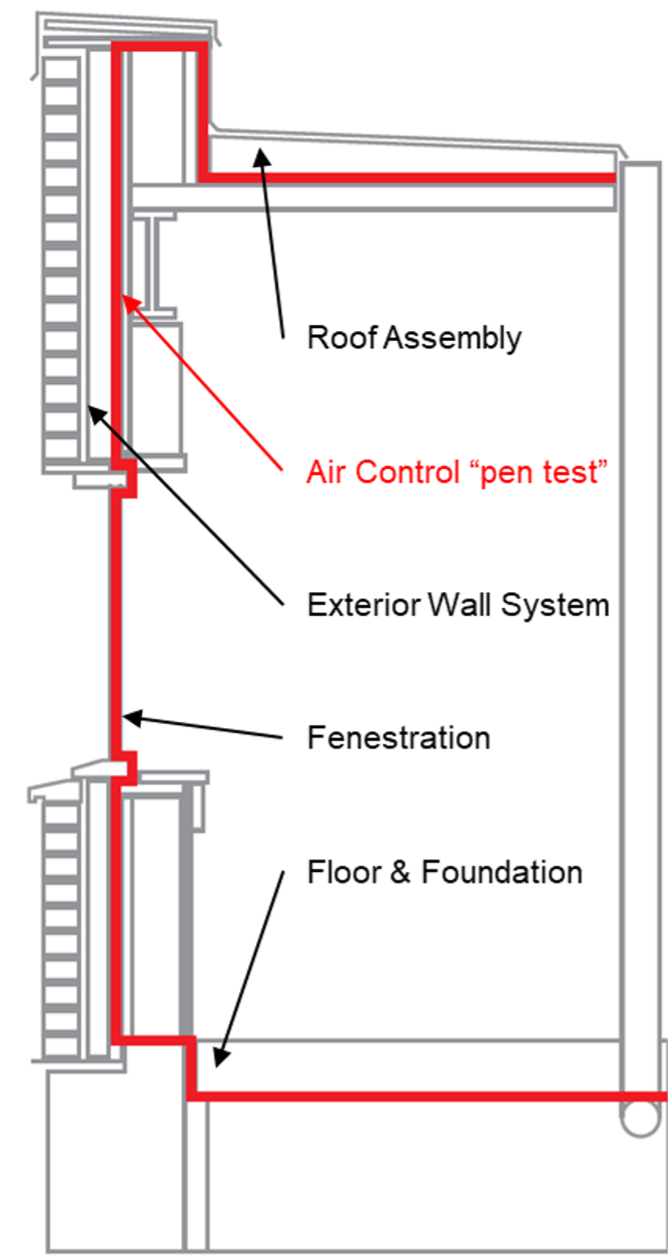
Image courtesy of GAF
Example of a “pen test” shown, as a red continuous line is drawn across building envelope elements to verify no gaps exist.
Identifying and maintaining continuity of the four key control layers is important in the design phase. Detailing and identification of the control layers in the drawings is critical to ensuring that the design intent is implemented in the field. This can require the design and specification callouts to be very specific. If the sequencing of components or trades in the field impacts the intended continuity or performance of the control layer in the design, it needs to be addressed before construction starts to prevent rework.
At a critical interface like a parapet, proper detailing, installation coordination, and execution are paramount. Control layer discontinuities can lead to failures in the field. For instance, air leakage can lead to concealed condensation and interior moisture damage.
Low-Slope Roofs and Wall Air Barrier Assemblies
One problem confronting the design professional is that there are lots of ways to accomplish performance goals for the building. The questions of how to design and sequence the control layers to prevent issues in the building are not simple. The building code can further complicate the picture, as it requires both ambiguous and specific things. For example, air and thermal barriers need to be continuous. Exterior walls and roof assemblies requirements are separated, but flashing requirements tie them together.
The International Energy Conservation Code (IECC) is a building code created by the International Code Council in 2000. It is a model code adopted by many state and local jurisdictions in the United States for the establishment of minimum design and construction requirements related to energy efficiency. In 2012, the IECC first published air barrier requirements which state that “continuous air barriers shall be provided throughout the building envelope.” There are exceptions to this requirement, but these are diminishing with each new version of the code.
There are three ways of achieving compliance with air barrier requirements:
- Materials (i.e. prescriptive)—the IECC published a list of materials they consider to be air barriers. Materials not on the list must be tested and shown to have an air permeance ≤ 0.004 cfm/ft2 under pressure differential of 0.3 in. water gauge (w.g.) tested in accordance with ASTM E 2178.
- Assemblies—assemblies consist of materials and components (sealants, flashing, etc.) that when put together can create a continuous air barrier, inclusive of penetrations. An average air permeance ≤ 0.04 cfm/ft2 under pressure differential of 0.3 in. w.g. tested in accordance with ASTM E 2357, 1677, or 283 is required.
- Whole building airtightness testing—the air leakage rate of a completed building enclosure can be tested and confirmed to be ≤ 0.40 cfm/ft2 at a pressure differential of 0.3 in. w.g. per ASTM E779, ASTM E3158 or equivalent method approved by a code official. Whole building airtightness testing will no longer be just an option for most buildings starting with the 2024 IECC, making the continuity of the air control layer even more critical to a building’s success.
The use of vapor retarders in low-slope roof assemblies will determine how the different control layers are detailed at transitions and at the roof-to-wall interface. All vapor retarders prevent air movement, but not all air barriers stop vapor diffusion. That means that when design professionals designate the use of a vapor retarder in a roof system, that retarder is also acting as an air barrier. The caution when using the vapor retarder as the air control layer is that the vapor retarder needs to be sealed at all perimeters and penetrations in order to perform as part of the air barrier assembly. It needs to be flashed and sealed to the wall air barrier, so air does not penetrate the interface. Practically speaking, all vapor retarders are air barriers if they are installed continuously and sealed to block the passage of air.
Case Study: Construction Sequencing of Control Layers for a Balloon Parapet
Sequencing of construction is very important for the execution of the continuous control layers. Understanding how each of the details will be constructed and how the different trades will interact with each other during the installation process will ensure that each of the control layers is continuous. By thinking through this sequencing, and even detailing out the installation sequence for complex details, clarity will come to all parties involved.
In this example of a balloon parapet, fore-thought in the process is ideal. Once the roof deck is laid and the wall is framed and sheathed, place a piece of flashing over the roof-to-wall interface below where the parapet will be constructed. This flashing will allow for easy integration to the wall air barrier and allow for the layers to be properly ship-lapped, providing continuous water and air control between the roof and the wall assemblies. This loose piece of flashing on the corner allows future materials to tie in when installed. After the flashing is laid, the parapet is then constructed over it in a balloon-framed configuration.
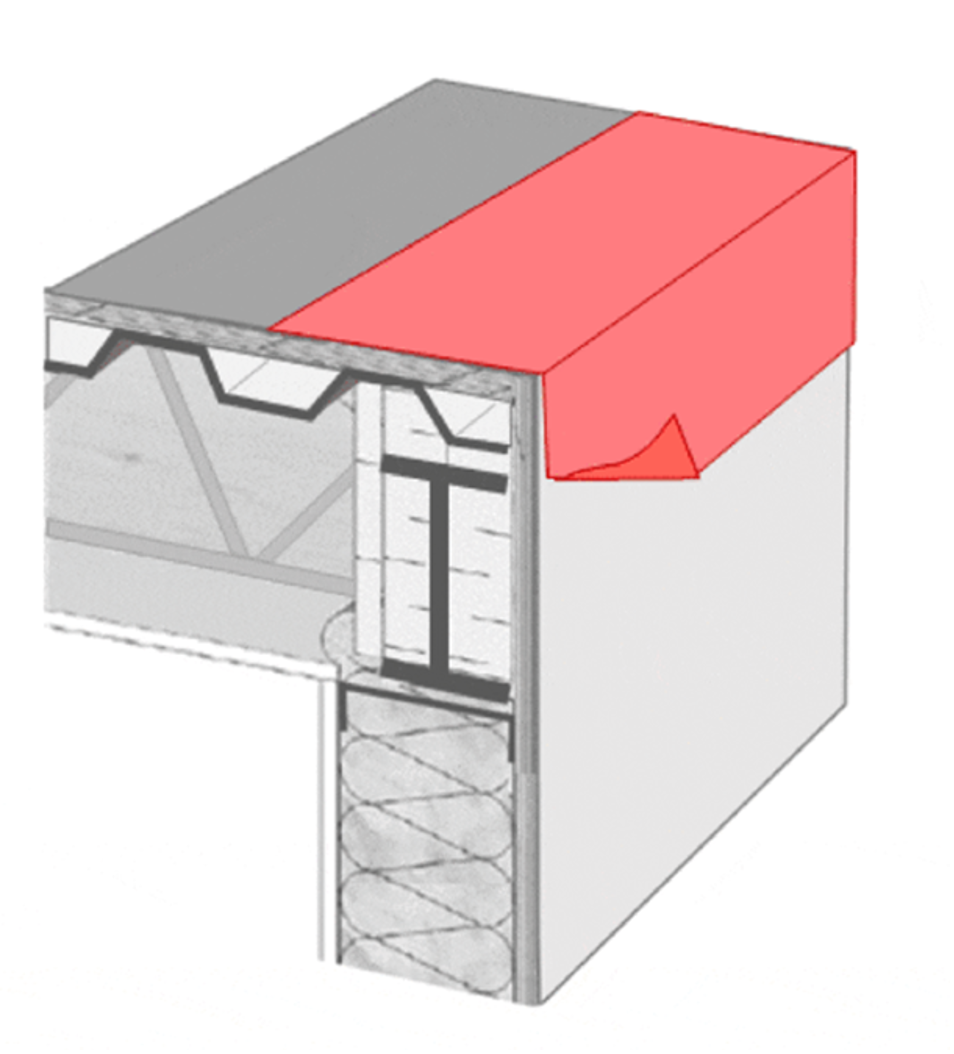
Image courtesy of GAF
Image 11 and 12. Sequence of Installation. Pre-treated corner and parapet wall.
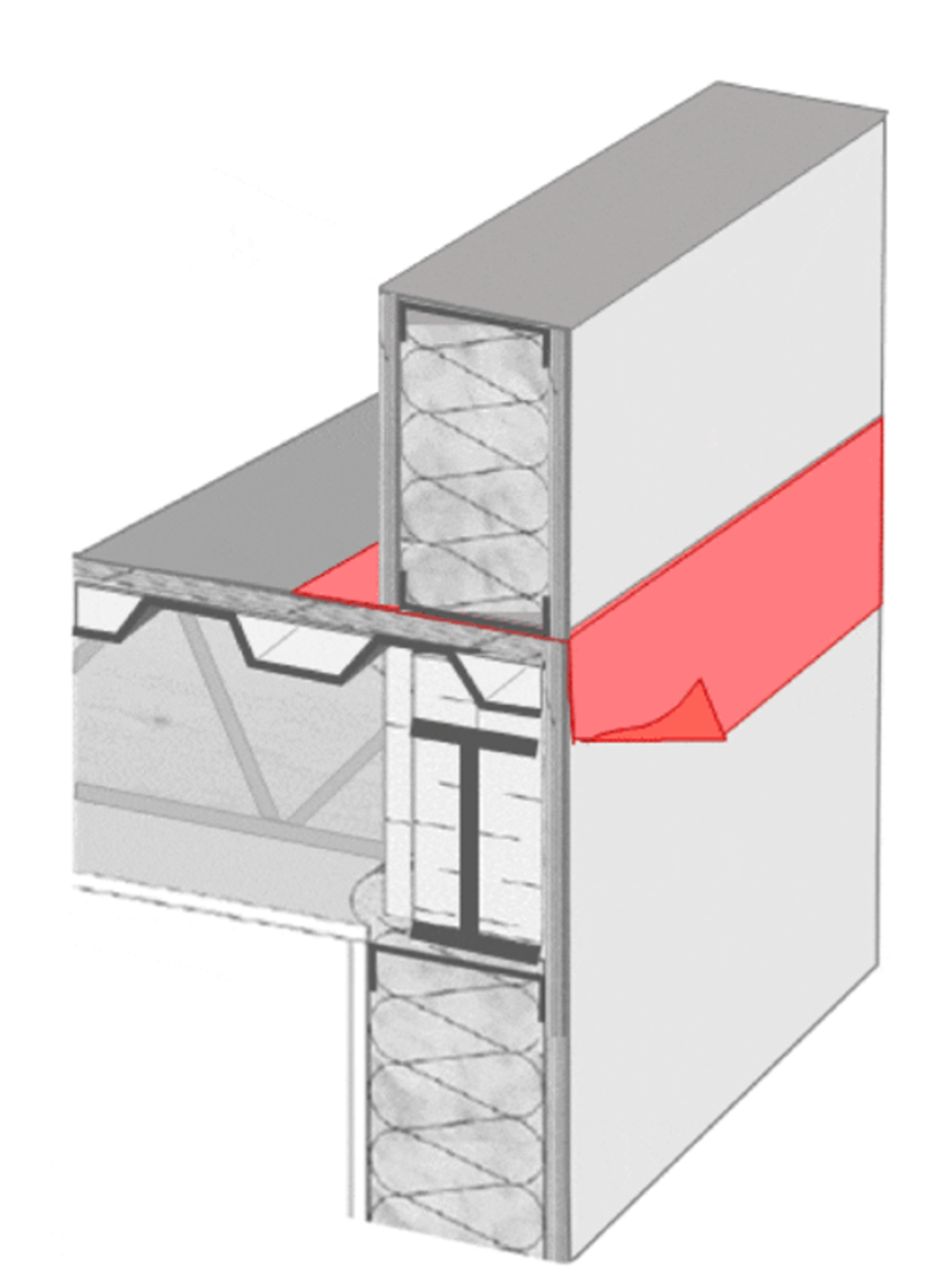
Image courtesy of GAF
Image 12.
Next, the remainder of the air barrier is applied to both the roof and wall systems, lapping over the previously installed flashing on the roof and over the top of the parapet. The flashing over the top of the parapet should lap over the wall air barrier, which itself laps over the flashing installed before the parapet was built. This creates full integration between the assemblies and provides proper lapping of the different layers. The air barrier on the remainder of the wall must lap under the flashing at the roof-to-wall interface.
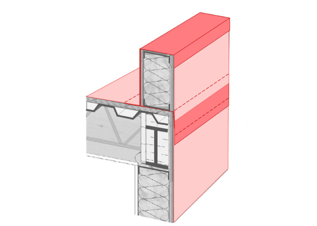
Image courtesy of GAF
Image 13. Air barrier integrated through interface.
Next, continuous insulation is installed as required by code. This provides the thermal control layer. Insulation is applied to the roof deck, back-side of the parapet wall, and exterior wall to maintain continuity. Ideally, there should be insulation on top of the parapet wall as well, especially if there is no insulation within the parapet itself. Redundancy and sufficient shingle- or ship-lapped insulation is important on the low-slope roof, as this installation method takes into account the expansion and contraction of layers that may occur during the life of the building and provides room for materials to shift without breaking continuity. Exterior wall flashing is installed to maintain shiplap and provide water control continuity at the area where the roof membrane will terminate.
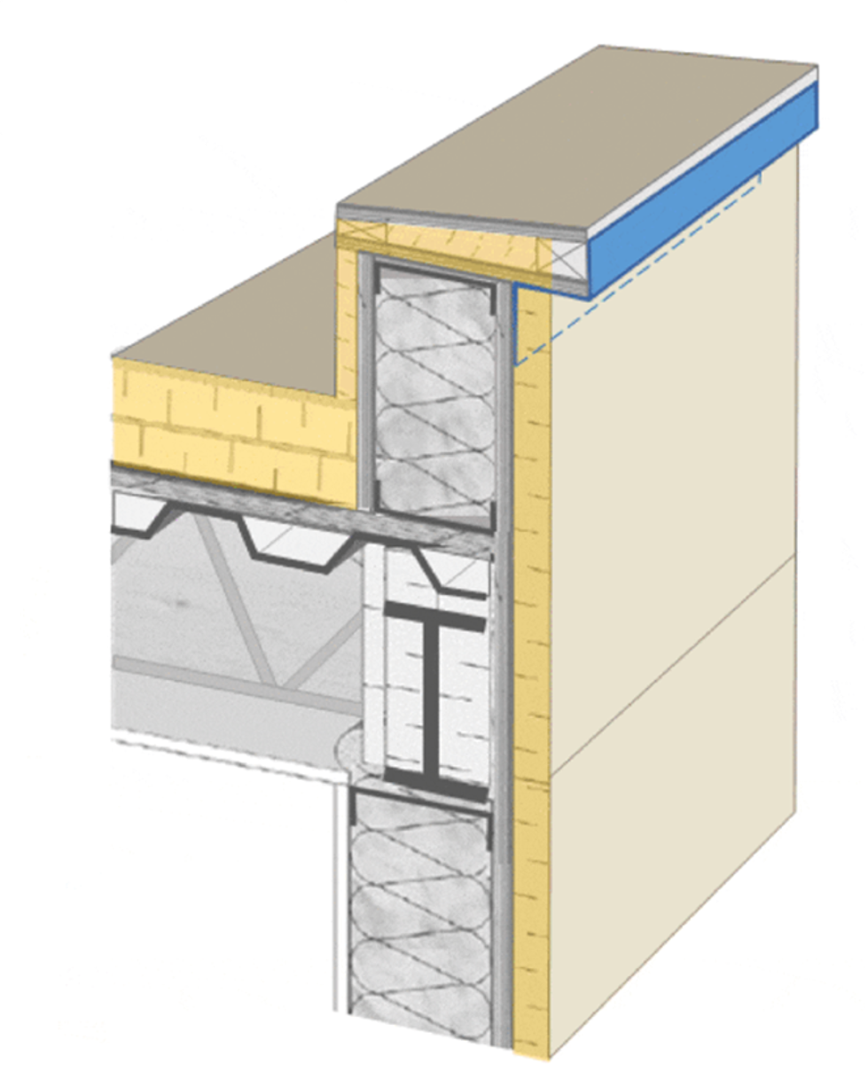
Image courtesy of GAF
Image 14. Continuous insulation installed (yellow).
The roof membrane is installed next. The roof membrane continues to the horizontal roof edge and is extended up the backside of the parapet wall. Depending on the roof membrane used, it can either continue up over the top of the parapet, or an additional piece of flashing will transition from the roof membrane, up over the parapet and terminate over the previously installed exterior wall flashing.
The outer water control layer on the wall assembly is never relied on to perform without any leaks, so a secondary membrane and control strategy is necessary. Typically, the air barrier material and assembly will also perform as the secondary water resistant barrier. The exterior wall flashing should be tied into and properly lapped onto the secondary water resistant barrier.
Finally, ANSI/SPRI ES-1 compliant coping is lapped over the cladding and the roof membrane or flashing with drip edges on both sides. It should also maintain an overall slope towards the roof system to shed water. It is important to have a negative slope off the coping, directing water back onto the roof and ultimately to the roof drains. The coping should also include drip edges to prevent water wicking up under the coping. When detailing and doing the “pen test” on the water control layer that has just been shown, it is critical that the line be continuous along the entire roof and wall.
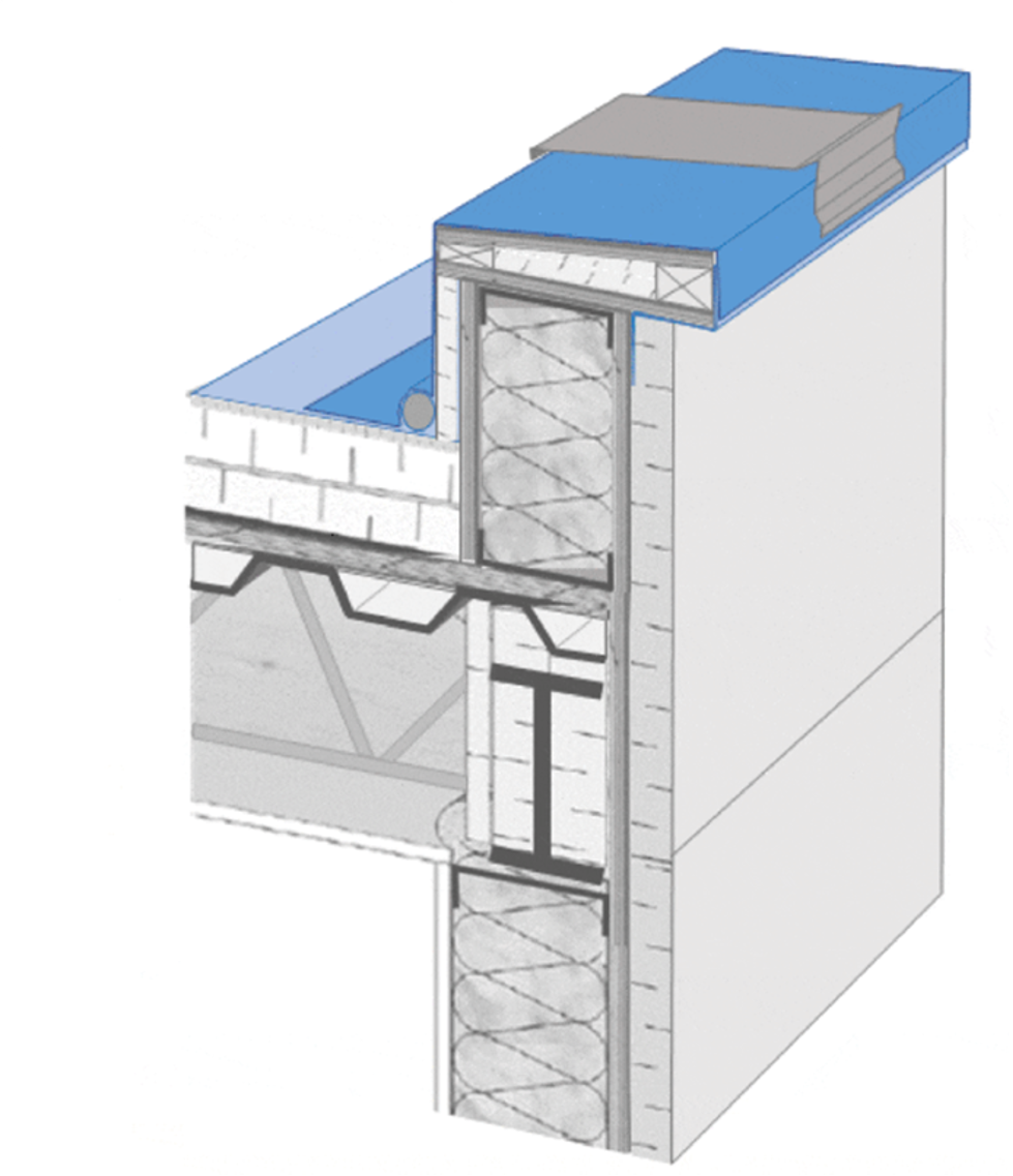
Image courtesy of GAF
Images 15. Roofing membrane installed followed by coping and cladding.
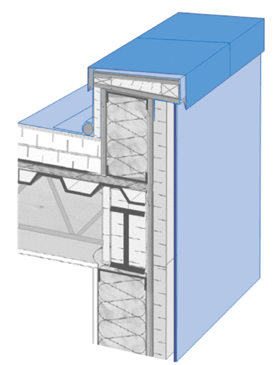
Image courtesy of GAF
Image 16. Roofing membrane installed followed by coping and cladding.
Thinking through how the roof assembly terminates and ties together at the interface of the wall and roof also has long-term ramifications for performance, maintenance, service, and potential re-roofing. The design team should consider the maintenance part of the lifespan of the building as well. Understanding the maintenance requirements and how a building manager will need to take care of these items over time will highlight if the details need to be adjusted for long-term performance. When the building is re-roofed, it is important that the design has enough vertical height to lay a new roof without reinstalling cladding, to properly terminate the new roof membrane into the existing wall assembly control layers and that there is necessary space available to include any additional insulation when a new roof is placed.
Notice