Risky Business


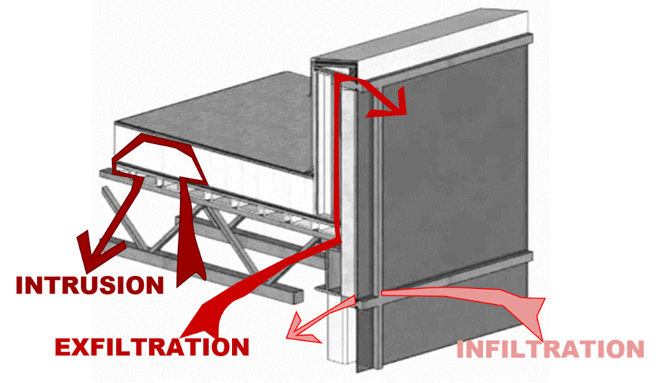
Image courtesy of GAF
Methods of air movement within a building.
To prevent the uncontrolled movement of air through the building enclosure, the air barrier must be made of systems and assemblies—a combination of materials working together—to prevent air leakage. The air control layer must be continuous across roofs and walls and must have continuity at interfaces. Per Section C103.2.1 of the IECC, it is the designer of record’s responsibility to detail the continuous air barrier around the entire building enclosure.
Several different roofing materials will block air and can be classified as an air barrier material. In order to fully function as the air control layer and be part of an air barrier assembly, these materials need to be installed and tied into penetrations and the wall assembly in such a way as to ensure airtightness at the interfaces. Consider how a roof membrane often runs up and over a parapet wall or is flashed at an exhaust pipe: the building designer needs to specify that the membrane not just overlap the wall air barrier or surround the pipe, but also that it is flashed and sealed to both in such a way that air cannot escape.
Thermal control principles
The thermal control layer follows the same principles as the other control layers. The thermal control layer is designed to resist the movement of heat from one side of the building enclosure to the other. Continuous insulation is unambiguous in the code, within IECC as well as the referenced ASHRAE 90.1. IECC C103.2 depicts the thermal envelope, and thermal bridging requirements are covered in IECC 402.7.5. Solutions for details like parapets will depend on construction type, location of insulation in the wall and roof assemblies, and design preference for the boundary of the conditioned space. Any breaks in the thermal control layer or insufficient insulation will increase the risk of condensation occurring at that location, whether it be from humidity in the conditioned space or uncontrolled water vapor entering the assembly from elsewhere.
Vapor control principles
The vapor control layer can be the most challenging of the control layers. The vapor control layer is responsible for slowing the movement of moisture vapor through the building enclosure. As defined by the IBC, moisture vapor will stop moving at a material with a permeance of <0.01 perms when tested to ASTM E96. As such, a separate vapor retarder or vapor barrier may not be required and may actually cause damage to the structure if used improperly.
To avoid unintended consequences, the designer should first be aware of the vapor permeance of all the layers in the enclosure and verify the location of any low permeance vapor retarders in the assembly. If there is more than one low permeance vapor retarder in the assembly, moisture can get trapped between layers, leading to condensation and related issues. Ideally, the material with the lowest vapor permeance should be placed on the warm side of the enclosure assembly. To help ensure there is no issue with moisture vapor such as condensation occurring in the wrong location, a moisture analysis can be performed. Hygrothermal analysis such as WUFIⓇ can provide this information, but it also relies upon the assumption that there is a perfect air barrier installed. For these reasons, a separate vapor control material may not always be needed. The decision matrix for where a vapor retarder is located within the assembly comes down to building use, climate zone, the design of the enclosure, and outside humidity levels that need to be considered.
One area where vapor retarders can be beneficial is in low-slope roof decks. They can also be beneficial in buildings with large temperature differences from interior to exterior and with building uses that require high interior moisture levels, either from use or during construction. Additionally, a vapor retarder is advantageous above concrete roof decks where curing moisture can cause issues for the rest of the roof assembly.
Case Study: Examining Parapet Perplexities of the Control Layers
Parapets are a critical interface where building aesthetics meet performance. The 2018 International Building Code (IBC) defines a parapet as “the part of any wall entirely above the roofline.” It is also the junction where building aesthetics combines with structural performance, air and moisture management, energy efficiency, construction trade sequencing, and operational maintenance. At such a critical interface, proper detailing, installation coordination, and execution are paramount.
Most of the components of a roof system limit air infiltration and can be considered as air barriers. Is there a best practice location to stop the formation of condensation within the roof system?
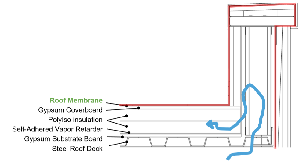
Image courtesy of GAF
Image 7.
If the roof membrane is designed and installed as the continuous air barrier going up and over the outside of the parapet, tying into the air barrier in the wall assembly, then air intrusion can potentially condense on cold surfaces within the roof assembly or under the top of the parapet. This is because conditioned interior air, as shown by the blue arrow in Image 7, can travel into the parapet. If any of these components or surfaces are below the dew point, moisture in the air will condense. Condensation is what can cause issues in this part of the building enclosure.
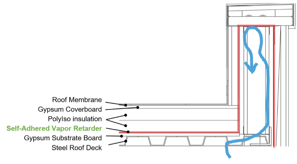
Image courtesy of GAF
Image 8.
Instead, a vapor retarder on the roof deck can be installed as and function as the air barrier. This will make it easier to bring the air barrier onto the inside of the parapet and interior to the insulation. Any air intrusion, as depicted by the blue arrow in Image 8 is less than in the previous option and there is no risk of moisture getting into the roof insulation. This configuration certainly helps prevent air intrusion in the roof system but may still allow air up into the parapet. Condensation may still occur on cold surfaces, especially if the top of the parapet has insufficient insulation.
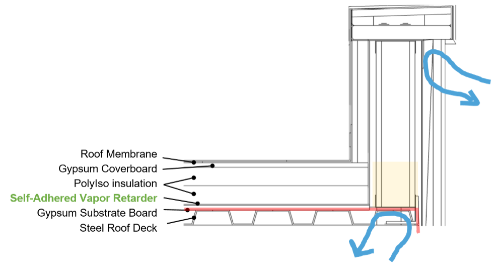
Image courtesy of GAF
Image 9.
One final option as shown in Image 9 is to remove the parapet from the conditioned space entirely. This starts in the same manner as the previous example with a self-adhered vapor retarder installed as the air barrier on the roof deck. The parapet is then at least partially filled with insulation allowing the air barrier to continue along the base of the parapet wall and connect to the wall air barrier. This placement keeps the air barrier on the warm side of the insulation in winter and prevents warm, moist air from getting up into the parapet cavity and roof structure where condensation could cause harm. This assembly design is now controlling air intrusion as well as air leakage across the building enclosure. If there are further concerns for a particular building, hygrothermal analysis can help determine if any condensation is likely to occur.
Proper Sequencing and Design of Control Layer Continuity
Key Point: Drawing the lines for all 4 control layers at each specific detail will help check for continuity.
These are some key strategies to maintain continuity of each of the control layers:
- Water control is managed first by the roof membrane and the cladding. A secondary water control layer, in the form of a water-resistant barrier or WRB, is often found in the wall assembly applied to the sheathing, typically behind or below the exterior insulation.
- Air control can be managed at the deck level of the roof, which can more readily be linked into the wall air barrier. The roof membrane can also be used as an air barrier as long as the detailing and transitions are done carefully.
- Thermal control continuity is maintained by connecting the roof and wall insulation, which can be challenging. This is easiest with continuous insulation on the outside of the structure. It is important to be mindful of cavity insulation or designs where insulation is split between inside the cavity and outboard of the structure, as there are potential risks for condensation due to the thermal bridges of the structure.
- Vapor control can be in the same plane and the same materials as the air control layer, depending on the building location needs, construction methodologies, product choice, and occupant use of the building.
Notice