Embracing the Timber Age


Window Rough Opening Detailing
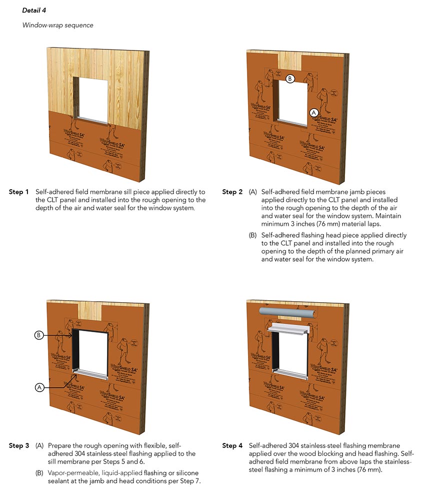
Shown in Detail 3a through 3d are typical window rough opening details. The opening wrap sequence, including integration with the WRB and AB membrane at the wall area field, is shown in Detail 4, window wrap sequence.
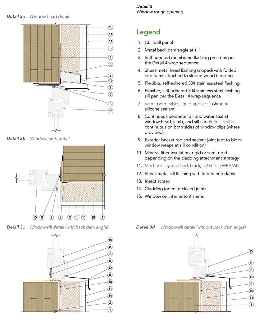
The interface where the window system meets the CLT panel is important because it can be a common source for water leakage if not designed and constructed appropriately. Appropriate detailing to provide continuous protection against water and air leakage requires that the WRB is flashed into the rough opening and a continuous air and water seal (typically a backer rod and sealant joint) is provided around the window perimeter.
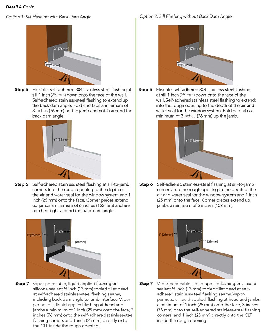
Best practice in some markets may dictate a metal back dam angle at the rough opening sill to form a sill pan. This angle may also serve as the structural attachment point for the window sill to avoid fastener penetrations down through the rough opening sill. Details for both a sill with a back dam angle and without a back dam angle are shown in Detail 3c and Detail 3d.
A sloped wood nailer is shown above the window as a thermally efficient attachment method for the window head flashing and to provide a solid substrate for the flashing membrane.
Typical Wall-Penetration Detailing
Penetrations through the WRB/AB or membrane are flashed with silicone sealant or a vapor-permeable liquid-applied flashing to maintain continuity of the drainage plane and AB. Typical penetrations encountered in the field may include CLT strap anchors, conduits, and flanged boxes, as illustrated in Detail 5.
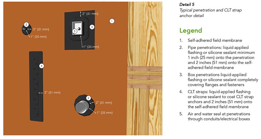
Penetrations are typically cut or cored through the CLT panel. It is best practice to pre-plan locations to mitigate any conflicts with other physical building components or with the construction sequencing.
Base-of-Wall Detailing
A typical CLT base-of-wall condition is depicted in Detail 6.
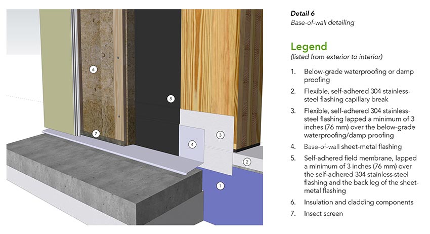
CLT is not used in below-grade applications, and local building codes dictate the minimum required clearance between the finish ground elevation and structural wood components that are supported by exterior foundation walls and footings. Typically, this requirement is 6–8 inches or the wood is required to be preservative treated. But regardles, 8 inches of clearance is best practice for CLT wall panels at exterior foundation walls and footings.
Best practice also dictates that the CLT is separated from the foundation using a vapor-impermeable membrane to provide a capillary break and barrier against burrowing insects. In Detail 6, this membrane is provided by the flashing. The sheet-metal flashing at the base of the CLT deflects drained moisture out of the assembly and away from the below-grade assembly. While the insect screen at the bottom of the cladding opening helps to prevent pests from burrowing into the assembly cavity, additional protective measures may be required in termite-prone areas.
CLT Roof Design and Best Practices
Roof structures can be classified by their pitch, and the approach to water and moisture management at roof assemblies typically varies based on roof pitch. Strategies for the design of exterior insulated CLT roof enclosures sloped at a pitch of 2:12 or greater, as shown in Figure 3-5, and at less than 2:12 are discussed separately. It should be noted that CLT roofs insulated from the interior are atypical in cold climates and require careful consideration of the air- and vapor-permeance properties.
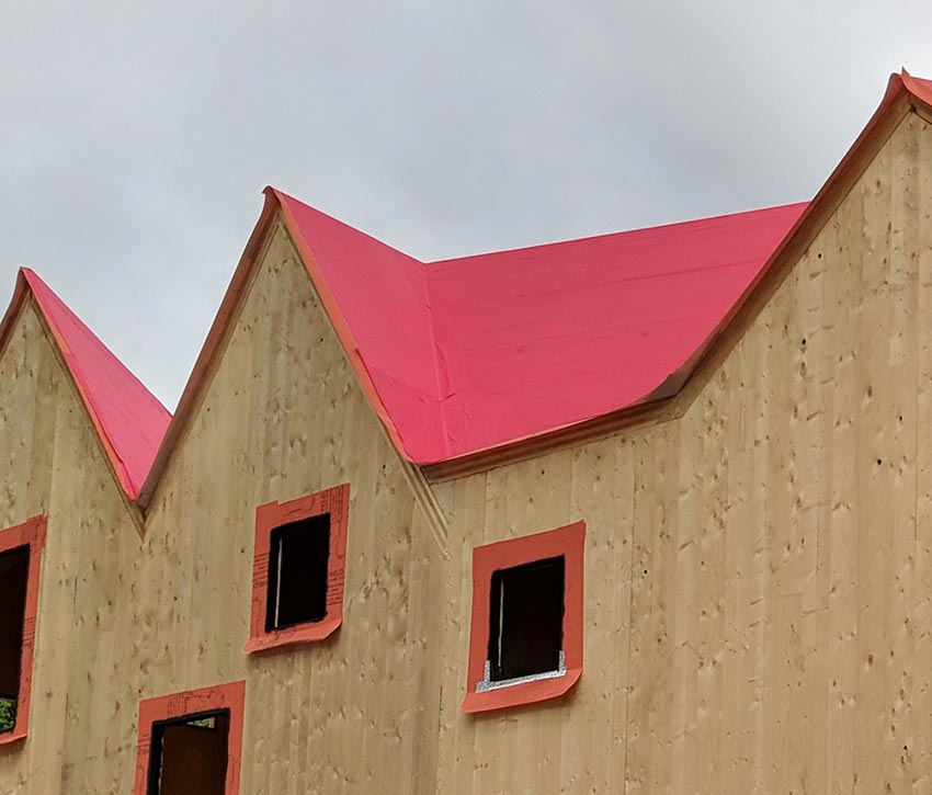
Figure 3-5
A vapor-permeable AB roof underlayment is installed over a gabled CLT roof at Haus Gables in Atlanta, designed by Jennifer Bonner.
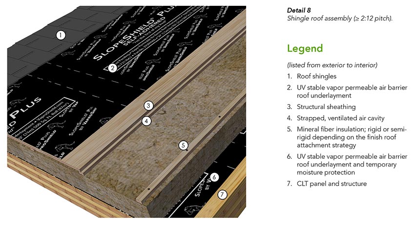
CLT Roof Design for ≥ 2:12 Pitch
Details 7 and 8 illustrate two CLT roof assembly options with a 2:12 or greater slope. These assemblies use a UV stable AB roof underlayment at two key locations:
As a roof underlayment beneath the finish roof material. At this location, the membrane sheds water that may bypass the finish roof material and also protects components below from moisture.
Over the top of the CLT. At this location, the membrane serves as the AB and also minimizes the risk that the CLT panel is exposed to moisture should a failure in the assembly components above occur. This membrane layer also serves as a temporary roof membrane to protect the CLT structure from construction-phase moisture until the remaining assembly materials are installed.
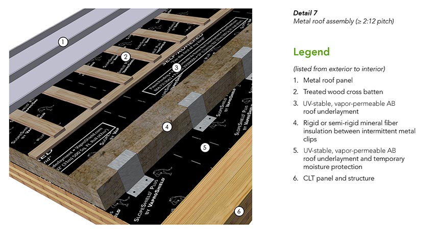
In both assemblies, vapor control is provided by the CLT panel. Unlike most common roof underlayment products, the AB should be vapor permeable to allow for some drying of the CLT substrate after application. It also offers extended UV stability and can be left exposed for up to six months prior to cover to provide greater flexibility in the construction schedule as compared to less UV-stable underlayment products. It is also important to consider that some finish roof materials, such as metal panels, may require a high-temperature underlayment membrane. The vapor-permeable AB can be used in high-temperature roofing applications with acceptable service temperatures up to 225 degrees Fahrenheit.
Depending on project-specific requirements, the assembly shown in Detail 7 can be made more durable by fully adhering the top layer of underlayment to a solid sheathing layer such as plywood, similar to what’s shown in Detail 8. Another drainage matrix may also be added above the roof underlayment where a ventilated and drained cavity is required by the finish roof manufacturer if the finish roof is not attached using a batten system or similar standoff.
The remaining assembly layers in Detail 7 and Detail 8 include:
- Layers of mineral-fiber insulation, as required to meet the targeted thermal performance of the roof assembly. Rigid mineral wool insulation is required when long screws are used for the direct attachment of the nail base sheathing to the CLT, and semi-rigid insulation may be used when the attachment is through a system of clips or similar methods.
- A strapped and ventilated air cavity to further encourage drying below the finish roof materials.
- Finish roof materials (e.g., metal panels, slate tiles, asphalt shingles, etc.) attached to a plywood substrate or treated wood cross battens.
Roof-Penetration Detailing
A typical penetration detail for a CLT roof assembly sloped at 2:12 or greater is shown in Detail 9. Similar to wall penetrations, the placement of roof penetrations requires planning to prevent construction conflicts. Penetrations through the roof underlayment are flashed for continuity of the WRB, AB, and/or temporary moisture protection layer.
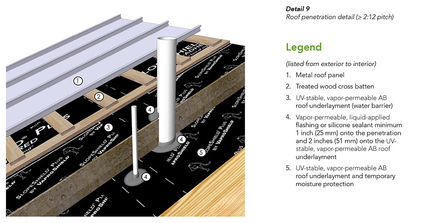
Fastener penetrations at structural clips and similar penetrations used for the attachment of the finish roof and sub framing may also need to be considered. At slopes less than 4:12, vapor-permeable liquid-applied flashing or neoprene shims must be provided under metal clips and similar penetrations to improve the sealing around fasteners. Additional treatment at clips for roof slopes of 4:12 or greater are not required.
Notice


