Introducing the Steel-Plate Composite Core


The Details
Delving into the details of the project’s design and construction, the super-structure will be erected in sequence, thereby avoiding the time restriction imposed by coordinating with a traditional concrete core construction.
In a Rainier Square Development white paper on the project, penned by Klemencic and Varma along with Klemencic’s MKA colleague Brian Morgen, Ph.,D., P.E., S.E., the engineers describe the system as prefabricated wall panels and boundary elements comprised of steel face plates, typically ½ inch thick, separated by 1-inch-diameter cross-connecting tie rods spaced 12 inches on center, both horizontally and vertically, with an overall wall assembly thickness varying from 21 to 45 inches.
Wall panels, on average, measure 13 feet 9 inches tall by 37 feet long, are being prefabricated off-site and will be shipped in stacked groups.
The wall panels, along with integrally detailed concrete-filled coupling beams, will be erected at the same pace as typical steel erection. The prefabricated wall panels are designed with enough strength and stability to support up to four floors of steel floor beams and metal decking before being filled with concrete. Furthermore, the face plates will serve as permanent formwork for the infill concrete.
Klemencic, Varma, and Morgen also note that the cross-connecting tie rods will be critical to the overall performance of the system as they serve multiple purposes, including:
- Strength and stability of the unconcreted wall panel to support erection loads;
- Lateral resistance and face-plate bracing during the concrete infill operation;
- Mechanical connectivity between the steel plates and in-fill concrete for composite action, leading to enhanced axial and shear strength;
- Confining pressure for the concrete for superior seismic performance under ultimate demands;
- Delamination of the steel plate and concrete infill is prevented;
- Out-of-plane shear strength; and
- Slenderness of the steel plates is reduced.
Once the walls are erected and the panel-to-panel connections are made, concrete will be piped into the space between the two plates with a self-consolidating concrete mix.
“The concrete combined with the steel plates provides the ultimate strength and stiffness for the core wall assembly as a composite section,” they explain.
Fabrication and Construction Challenges
In order to create the prefabricated units, approximately 500 panels and 200 boundary elements are being prefabricated. As part of this process, the fabrication sequence and connection of the tie rods are critical to the panels’ efficient and timely fabrication.
Similarly, panel-to-panel connections during the site erection sequence are also a critical detail of the system, something that is particularly key for a high-seismic zone like Seattle. Addressing this issue, welded connections are being exclusively used in order to ease field fit-up and speed construction. Furthermore, Klemencic, Varma, and Morgen explain that project-specific, prequalified welds have been developed and are being tested to add to the efficiency of the connections.
In terms of the penetrations that must be made through the composite steel plate, Klemencic points out that this process is inherently easier than reinforced concrete because unlike the former, the rebar is visible. That said, MKA encouraged the project team to coordinate all of the MEP openings early enough in the process so that they could be included in the shop fabrication in order. This will ultimately save the costs of adding them in the field.
Set to commence later this summer, the team anticipates that erection will take a year. Putting this into perspective, erecting the entire building should take less time than casting just the concrete core of a conventional concrete structure.
“The final assembly will be spray fire-proofed in order to satisfy the jurisdictional requirements for a 3-hour assembly,” they report.
At the same time, the CF-CPSW is being studied to better understand the fire performance of the system to determine if minimizing or eliminating the need for supplemental fire protection for some portions of the system might be possible.
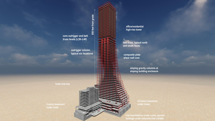
In terms of the floor plate, there will be seven levels of underground parking, and retail and offices until level 37. The next three floors will house mechanical, elevator transfer, and amenity levels, and the upper 18 floors will house 200 residential units.
A few floors up, the south face slopes inward, with a more pronounced slope designed for the east side. Starting at 140 feet by 245 feet, the footprint gradually shrinks to 120 feet by 120 feet once it ascends to the 40th floor.
Interestingly, the original Rainier Square design called for a concrete core, but the mid-height embedded outrigger trusses required to stabilize the tall, thin building would have been more costly and time consuming.
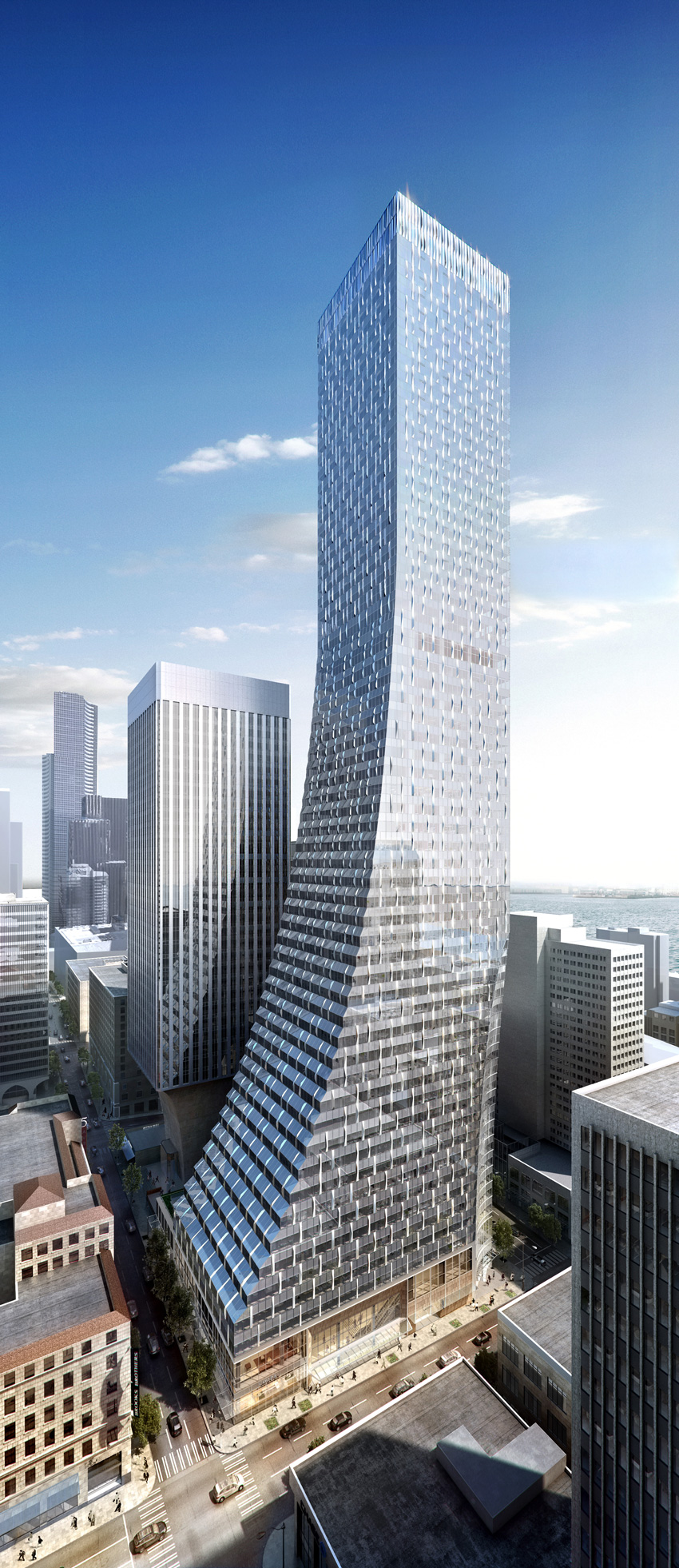
Image courtesy of MKA
As the first high-rise project to incorporate the CF-CPSW system, the 58-story Rainer Square Tower in Seattle is expected to shave several months off the construction schedule and 2 percent off the construction costs.
It was at this point that Wright Runstad challenged the design team to come up with a lower-cost structural solution and a faster time line. Klemencic, who had already developed the CF-CPSW system, saw this as an opportune time to suggest the system, and the structural design was soon altered to incorporate the system.
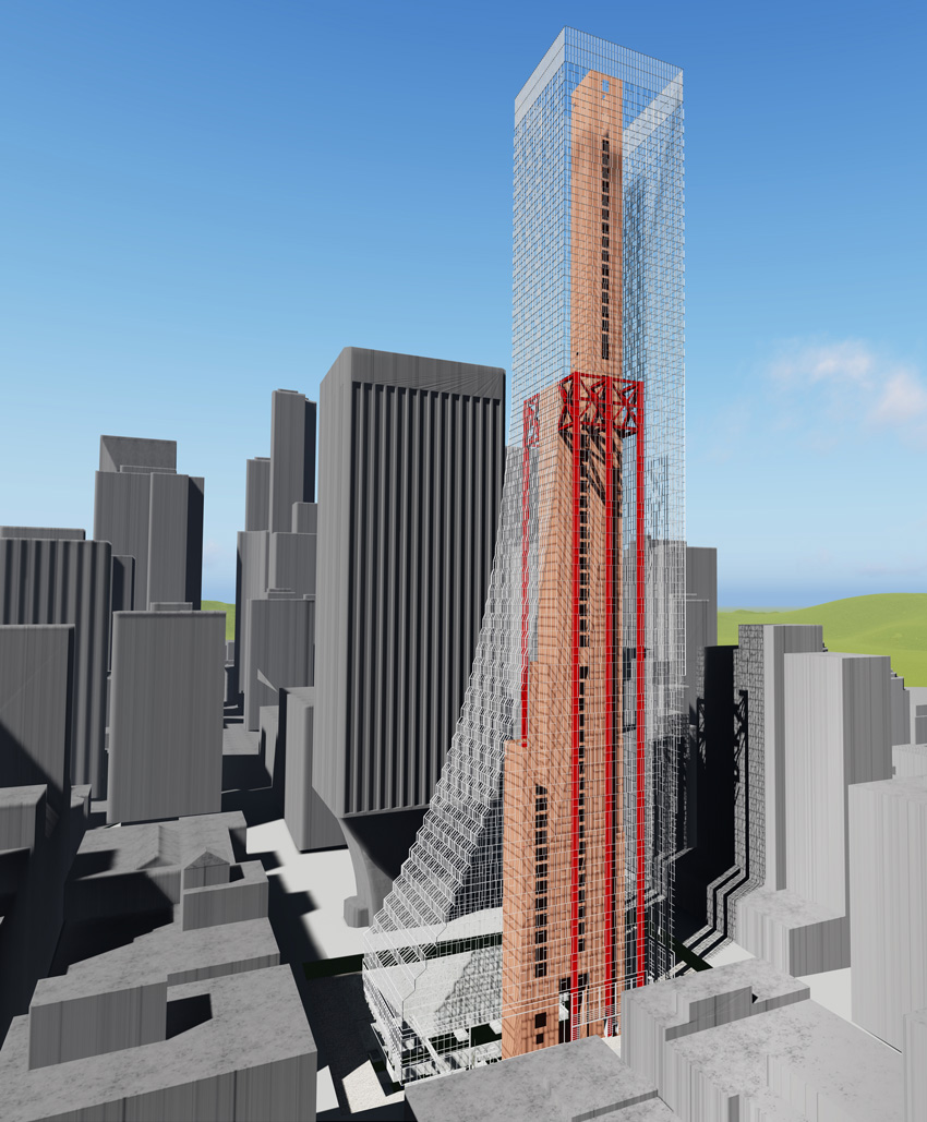
Of course, as a high-rise subject to high wind, the CF-CPSW still required stiffening, so three lines of 40-foot-deep outrigger trusses with buckling-restrained braces (BRBs) from floor 38 to floor 40 were designed to span from the core to steel perimeter box columns with crossties. These ties will confine the box columns’ cast concrete infill and lend stability during construction.
According to Klemencic, the BRBs will absorb quake energy like fuses by going through their yield cycle, providing the required support and capping the load to the outrigger columns. “The CF-CPSW interfaces more readily with the outrigger trusses as all of the connections are steel to steel as opposed to steel to concrete,” he explains. “This greatly simplified the connection detailing, fabrication, and erection.”
The outrigger columns are interconnected by east-to-west perimeter trusses, which provide a redundant load path. A 12-foot-thick mat, measuring 180 feet by 128 feet, will support the outrigger columns, most of the wide-flange perimeter columns, and the 870-foot-tall core, with a maximum footprint at the base of 93 feet by 40 feet. Gravity-only columns at the base, outside the mat, will bear on spread footings.
Because the system is so new, it has yet to be codified and therefore required a performance-based seismic design approach. While the City of Seattle welcomed the CF-CPSW system, it did so with the caveat that it be reviewed by three structural peer reviews, including two practitioners and one academic.
Because the system has never been built, the team felt it was prudent to build two mockups, according to Klemencic. “One to test concrete placement methods, mix designs, and consolidation, and a second to test steel shipping, handling, erection, fit-up, and connectivity,” he says.
Images courtesy of MKA
For seismic protection, MKA designed three lines of 40-ft-deep outrigger trusses with buckling-restrained braces (BRBs) for Rainier Square’s floors 38 to floor 40.
More specifically, the first mockup helped to determine the number and location of access ports for the hoses and to evaluate different baffle-hole layouts in the boundary elements, and measure and monitor the concrete temperature.
Notice


