Using 3D Printers to Create Architectural Models


Basic 3D Printing Process
While there are a number of variables in the equipment, material, and output sizes in 3D printing, the basic process is the same in most cases. The beginning point, just as in any architectural modeling process, is the development of a design. That design can be simple for the purpose of determining basic form or massing, or it can be detailed for the purpose of understanding the interactions of different building components. Either way, a computerized design file based on a three-dimensional representation of the building is the starting point. Many architectural designs already start that way using CAD or building information modeling (BIM) software. The beauty of 3D printing is that early designs can be quickly and readily tested, observed, and compared by printing out different concepts or variations.
With a computerized design in place, there are essentially three steps that occur in the 3D printing process for an architectural model:
1. Pre-processing: defining layers. In this step, the design is “sliced” or sectioned into layers. This is accomplished by creating a “build file” based on importing a 3D CAD file into a printing software program installed on the computer. Note that if the finished model is larger than the size of the 3D printing chamber, then it will need to be prepared in parts or sections that can be assembled afterwards. Those sections will need to be identified and treated as separate printed outputs. Regardless of size, some options related to specific material, color, and slice thickness may need to be selected if the 3D printer has multiple choices for these. In some cases, it may also be necessary to pick a “build and support” style to match the requirements of the object being created. Supports may be needed to temporarily hold in place parts of the object that overhang or cantilever out or otherwise need scaffolding style stiffening until the material solidifies. Some of this may depend on the orientation of the model being printed so selecting that orientation may need to be done as well (i.e. printing on its side or even upside down if that is more practical).
Once the choices are made, the preprocessing software calculates sections and slices the design into many layers, ranging from 0.005 inch (0.127 mm) to 0.013 inch (0.3302 mm) in height. Using the sectioning data, the software then generates “tool paths” or building instructions, which will drive the printer or extrusion head. This step may be automatic when using certain software. Once complete, the printing job is ready to be sent to the 3D printer.
2. Production: the layering process. The 3D printer needs to be prepared and ready just like any other printing machine. Most have fully enclosed chambers where the 3D object is created on a base or platen that moves vertically along the Z axis. They also have a place for the plastic material to be loaded, just like loading ink cartridges in a paper printer. The platform on the bottom of the chamber is usually not the place to have the model built, rather, a base made of wood or plastic should be positioned so the finished result can be easily lifted out. Once ready, it can be as simple as pressing “print” or start to allow the chamber and the plastic material to heat up to the appropriate temperatures.
The building process begins with the printing platform, or platen, moving vertically into position. Typically, this platen moves down in measured distances along the Z axis as material is deposited in layers. After each layer is complete, it lowers slightly to make way for the next layer. In the FDM process, the extrusion head, which moves about on an XY platform, lays down a ribbon of material. Two materials may enter the extrusion head—one or more to make the object, and one to support it. Heat is applied to soften the plastics, which are extruded in a ribbon, ranging in size from a human hair to heavy twine. Alternating between model material and support material, the system deposits layers as thin as 0.005 inch (0.13 mm). Each layer of molten plastic is deposited on top of the previous one and flattened slightly by the extrusion head. In most cases, the layers instantly fuse to one another.
The accuracy and precision of the FDM printed object relies on the coupling of material feed rates and extrusion head motion. Both are constantly changing to produce a flat ribbon of material. Drive wheels push the plastic filament into the hot liquefier section of the tip assembly. The pressure forces the plastic through a tiny orifice in the tip, which presses down to flatten the bead. Meanwhile, the head accelerates and decelerates as it travels across the platen. As the head speed changes, the drive wheels adjust the material flow rate. The result is a precise ribbon width that adjusts as required to produce the object. On the highest-performance machines, accuracy or tolerance reaches as high as 0.003 inch (0.08 mm), which rivals the accuracy of injection molding for machinery.
In the PolyJet process, the jet-heads spray a layer of material along the X and Y axes that is essentially tiny droplets of liquid photopolymer instead of the heated ribbons used in FDM. Once in place, this photopolymer layer is immediately cured with ultraviolet (UV) light and becomes solid before the next layer begins. Depending on the size and ability of the printer, as many as three different materials may be mixed at once during the printing process to create different colors, transparencies, or flexibilities. As the PolyJet printing process continues, multiple fine layers accumulate on the build tray to create a precise 3D model or part. Where overhangs or complex shapes require support, the 3D printer builds a removable gel-like support material.
3. Post-processing. When the object or model is complete, the printing chamber can be opened and the model removed. By this time, the supports have served their purpose and can be separated from the model. If a soluble support material is used, then it can be literally washed away in a tank that contains water and detergent. If a washable material is used, it can be jet washed with water. If break-away support material is used, then it manually needs to be twisted, broken, or scraped from the primary model using common hand tools. Once complete, the model is ready to use.
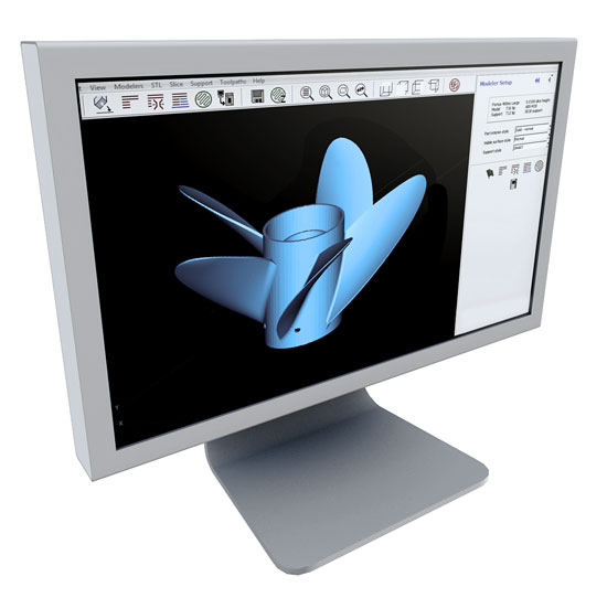
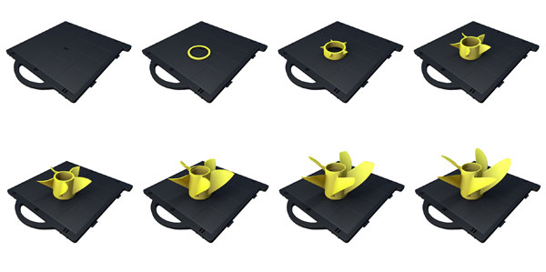
Image courtesy of Stratasys, Ltd.
The additive process of 3D printing is based on using a computerized file to slice an object or model into three-dimensional layers that are placed sequentially from the bottom up.
Notice