This CE Center article is no longer eligible for receiving credits.
On all buildings, the outer skin (e.g., the facade) performs all of the same functions that the skin on our body does. In both cases, it is the skin that protects the inside from the elements like sun, rain, and wind. It regulates the flow of moisture by allowing it to permeate through the skin when needed or prevent it from passing at other times. It helps regulate our temperature in conjunction with insulating layers. It absorbs or reflects light and heat based on the color and texture. In some cases, it can be self-healing or otherwise easy to repair when damaged. And, of course, we want it to look good and healthy not just today but over many years. In this course, we address these multiple aspects of building skins including their role in creating sustainable buildings. While the part we see is the outer surface of the facade, buildings like people, are much more than just skin deep.
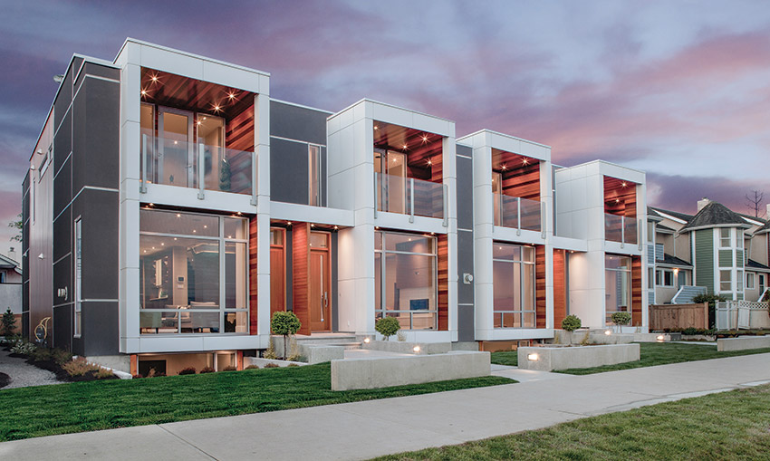
Photo courtesy of Low Hammond Rowe Architects
Dallas Road Townhouses. Building facades come in all types, styles, shapes, and sizes, yet they all need to be designed well for reasons of aesthetics, safety, sustainability, and overall performance.
SUSTAINABLE FACADE DESIGN
Facade design is part of every building project. The style, character, and visual appeal of a building are all part of the design considerations. In addition, the performance in terms of energy flows, water control, moisture management, and impact on the surrounding environment all come into play too. Most facades are a combination of opaque wall areas and fenestration, each with their own contributions, or detractions, from the appearance and performance of a facade.
A primary design requirement from building owners, building codes, and voluntary standards is that the facade must meet criteria for sustainability and resilience. Doing so is a multi-step process with many different, sometimes competing, considerations. Fortunately, things have evolved to the point where aesthetics and sustainable performance can be blended into a complementary and successful solution. The application of continuous insulation over a structural system of whatever type is becoming more common and readily achievable to produce higher thermal performance in most climate zones across the US and Canada. Air and water barrier products are more plentiful with more options for application types to effectively control air infiltration and manage vapor transmission. Cladding and rain screens have become well developed including some sophisticated means for supporting them. All of these components go into a facade design, so understanding not only their purpose, but also their material makeup plays directly into creating a sustainable facade.
Images courtesy of Habit Studio
Falkland Street Project. BIM software allows designers to visualize different building designs while providing data related to performance and sustainability.
Design Strategies
Architects and other building design professionals seeking to achieve sustainable facades can learn from some strategies that have been successfully used by others including the following.
- Consider Lightweight Cladding: Less weight usually translates into less structure to hold it up─not only in the framing but also in the foundation. In particular, the use of lightweight metal in facades can include rolled steel sheets, metal cladding panels, or composite metal panels. Metal building products, such as steel and aluminum, typically contain high amounts of recycled material thus lowering the amount of embodied carbon in the products. Masonry and concrete or other cement-based products are fossil fuel intensive to produce with high levels of embodied carbon. Metal fabrication can have even lower carbon footprints when the electricity used in the process comes from renewable resources like wind, solar, or hydropower. Finally, the ability to recycle and upcycle metal materials at the end of their service life also improves their sustainability.
- Prioritize Adaptive Reuse or Historic Preservation: It is often said that the most sustainable building is an existing one. The same is true of facades. If a building renovation project includes facade work, focus first on the ability to save and re-use what is there before automatically assuming everything has to be removed and done over. This could include selectively removing only things that are outdated or deteriorated but keeping the things that are still usable while their replacement would create more work, and more emissions, to produce and install.
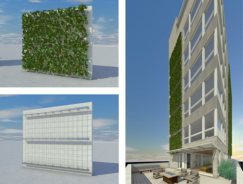
- Account for Siting and Building Orientation: Facade skins can always get a little help from their surroundings. Siting and building orientation play a big role in the amount of wind, sun, and weather that a building facade is exposed to─and it may be different on different sides of a building. Trees and other vegetation can provide some shade and protection while surrounding buildings in an urban setting can do the same thing. In cases where facades are fully exposed, adding elements over fenestration is a common approach to improve shading and overall performance. Strategies can include horizontal or vertical sun shading systems as conditions call for. They can also include planted green facades to add a natural, biophilic solution.
- Anticipate Climate Extremes: Many buildings are being subjected to more extreme conditions than previously due to climate change. The frequency and severity of storms and the intensity of temperature and wind conditions have made historical data alone unreliable as a design guide. Similarly, climate zone designations have been a useful benchmark for climate conditions, but individual sites can have widely varying conditions. Hence, it has become prudent to include measures for increased resistance to these extremes as a means of creating more resilient, and therefore more sustainable, buildings.
The design process of achieving a truly sustainable facade has changed in recent years. It is no longer a matter of just picking a few products out of a catalog and calling it done. Rather, detailed information is needed not only on the technical aspects of the products’ performance but also on their ability to be compatible with other products and with building codes. Similarly, there is a need to have information about the environmental impacts of the products selected which is often found in Environmental Product Declarations (EPDs). Managing all this data can be quite difficult if done manually or in a piecemeal fashion. It is more effective to use computer-based data coordinated with Building Information Modeling (BIM) software. A key advantage of BIM software is that it provides the ability to readily visualize, test, and analyze a variety of different building facade designs in order to arrive at the best outcome. The algorithms and visualization tools inherent in BIM inform design professionals how a specific project will both look and perform in a particular site and in light of the natural elements there. In this way, an integrated planning and design process can be employed to ensure a project is set up for success to meet all project goals, including sustainability, from inception through to completion.
DESIGNING FOR MOVEMENT
The design of facades for larger buildings needs to consider the fact that building structures, and their facades, must be allowed to move. That movement is accommodated by designing predetermined gaps into large structures that can absorb the motion. In large buildings, they are a necessity, particularly where buildings are segmented into different sections or if one attaches to another structure such as a parking garage or other use. The location, size, and movement requirements for all such expansion joints are project-specific and appropriately established by the Structural Engineer of Record.
Some design conditions directly affect the way expansion joints are worked into a building. For example, facades and exterior elements often have complex geometries that can converge in a range of locations such as at grade, under entry portals, at beltlines, across patios, soffits, etc. It is also common that multiple materials are used for aesthetic or functional purposes on a building. All of these conditions directly affect expansion joints, requiring them to accommodate differing materials─to invert under patios, climb up and over parapets or elevator mechanical rooms, negotiate curbs or rooftop gardens, etc. These locations are also where a range of trades can come together for the different materials and systems being installed. Not surprisingly, these locations are also the sources of most leaks or breaches in the envelope related to water, air, or thermal compromises. Therefore, providing properly coordinated details that can be used by the trades to address these situations can be critically important in maintaining the integrity of the facade across the expansion joints and the areas around them.
Images courtesy of Habit Studio
Expansion joints in a facade can blend in with the surrounding material or be designed to make a visual statement. Either way, they need to be located and installed properly to address the different types of movement to which a building and facade can be exposed.
Unfortunately, very few projects containing expansion joints are ever detailed to such a finite level. This leaves most contractors, facility managers, owners, and potentially architects to deal with the consequences of uncoordinated expansion joint systems for years to come. Industry data suggests that expansion joint issues account for the second highest recurrence of the owner's first year callbacks to the contractor (The #1 reason remains HVAC balancing problems). The owner’s issues generally surround frustration with joint systems- whether for functional, aesthetic or leak-resistance purposes.
The first step to proper specification and detailing of a joint system is to acknowledge the nominal joint size for a particular building and the range of movement between the fully contracted size and the fully expanded size. The design width of an expansion joint at an average air temperature is referred to as the nominal joint size. The building movement that makes expansion joints necessary occurs due to several common reasons with three types of movement that typically need to be accommodated:
- Thermal Forces: This type of movement is most typical and caused by daily or seasonal environmental temperature changes in and around the structure. Thermal movement is primarily “one-directional” in nature and is the result of the expansion and contraction of structural elements as affected by heat, cold, and humidity levels. The typical amount of thermal movement is approximately 10-25 percent of the nominal joint size. That means the maximum expanded joint size where the building sections contract away from each other (i.e., during cold temperatures) should be 10 – 25 percent more than the nominal joint size. Similarly, the minimum contracted joint size where the building sections expand toward each other (during warm temperatures) should be 10 – 25 percent less than the nominal joint size. If expansion joints aren’t sized and installed properly, then the thermal expansion and contraction can cause buckling of structural surfaces and ripple along the facade and other surfaces.
- Seismic Activity: The shifting of the earth’s tectonic plates (i.e., earthquakes, tremors, etc.), and shifts along fault lines is the source of seismic activity. Seismic movement may be horizontal, vertical, in shear, or a combination of all three. Seismic expansion joint widths may need to increase with higher floor levels to accommodate the additional, cumulative movement that needs to be addressed. These joints must have the capacity for movement of plus or minus 50-100 percent of the nominal joint size associated with them. When it comes to expansion joint systems, it is important to select systems that can “reset” themselves after a minor seismic event without requiring workers to reposition any cover panels.
- Wind-Loads: Movement induced by high winds, can force the structure to sway. This movement is normally perpendicular and/or parallel to the joint. This is common where a low horizontal building span meets with a taller vertical element. Movement in these joints is typically on the order of 50 percent of the joint width. Over time, the near-constant effects of wind pressure on the sides of buildings can lead to serious issues such as aerodynamic instability, torsion or swaying, erosion of certain building materials, and cladding failure due to wind load or impact of debris. In extreme cases, it can lead to structural failure and damage to people and property. Therefore, when designing a structure, it must be able to both withstand high wind loads but also work with them. As with seismic activity, expansion joint systems should be able to “flex” and yet remain in place as the building sways or torques.
A growing concern regarding wind and expansion joints is related to more extreme environmental factors including increasingly higher wind speeds and the uplift/ pull forces they impose on the exteriors of buildings. Increased attention to wind uplift calculations has been occurring in engineering standards such as ASCE 7- “Minimum Design Loads and Associated Criteria for Buildings and Other Structures.” These standards have been changing in response to environmental and climate challenges that have become more intense in recent years. Similarly, California and Florida code research indicates more stringent scrutiny of resistance to extreme weather is being considered during the code plan reviews and architectural shop drawing reviews. This is leading to specifications calling for fully tested expansion joint cover systems that can meet standards such as ASTM E1399 (seismic cyclic movement testing), as well as ASTM E283, ASTM E330, and ASTM E331 (Water, Air, and Structural integrity tests). These are all now required to ensure the specified system will not only perform as intended but also reduce professional liability risk.
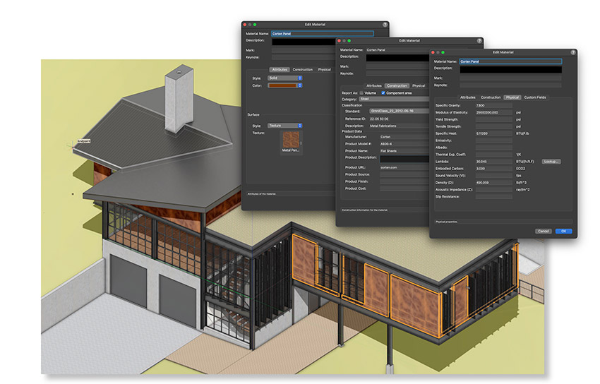
Image courtesy of Vectorworks
Product’s EPD data applied to wall components. Building Information Modeling (BIM) not only helps with the visualization of facades, but it also helps with the performance and sustainability of the building by using integrated data and reporting tools.
By properly addressing all these conditions, the building can be protected from the movement that will invariably occur and avoid the resulting damage that is possible.
Typically, if an expansion joint is needed in a facade, it also needs to run continuously through all adjacent planes to fully separate building sections and allow independent movement. That means that any given project could include interior joints, exterior joints, or both in things like walls, roofs, floors, building veneers, soffits, parking decks, patios, roofing systems, etc.
Recognizing the need for functional but aesthetically appropriate expansion joints, several manufacturers carry exterior wall systems that provide a functional system with options to infill a joint cover with material to match or blend with the facade material. These infill options could include but are not limited to metal panels, lightweight or thinned masonry units, EIFS or true stucco, spandrel glazing, and composite metal panels (CMPs). It’s worth noting that newer systems on the market have more overall depth than other systems and provide mechanical attachment points to give the designer and installer the most customization options within a standardized, cost-effective system. If the client chooses to utilize CMPs for their project, there are fire and dent-resistant expansion joint panels available.
USING BIM FOR BETTER FACADE DESIGN
Many architectural firms have embraced the use of Building Information Modeling (BIM) as a better, more coordinated, and more streamlined way to manage the design and construction (or renovation) of a building project. While the benefits of this approach are numerous, we will focus here on how integrated BIM software can greatly enhance facade designs as well by helping architects achieve a project’s optimal appearance and performance.
At the most basic level, BIM software allows architects to visualize how a project will look as well as perform against natural elements. The beauty of using BIM as a design tool is that professionals can quickly iterate different design options, wall assemblies, and material choices to compare the appearance of each and discern which is preferred. Similarly, the performance impact on the building and sustainability goals can be readily reviewed as needed to optimize outcomes. Integrated design tools aided by algorithms can help the design process with automation-enhanced testing of various scenarios. This integrated approach empowers designers to explore the aesthetic design features of a project with real-time rendering using a wide range of materials and textures resources. From a full facade planning standpoint, the software can also provide full visualization of sun paths and create sun studies as part of the design process. This can be invaluable in determining the degree of sun exposure and the appropriate means to address it, either for enhancing daylighting into a building or for shielding it from excessive solar gains.
Using data-driven design tools embedded in BIM objects helps architects make more fully informed design decisions. The data-driven design aspect of BIM software provides the opportunity to test the simulated or comparative performance of different design choices. This is possible because data from a BIM model generated with parametric building objects provides information to designers allowing them to make better design decisions. This can be most fully achieved by using BIM-generated automatic reports, quantity takeoff calculations, and schedules (i.e., room schedules, finish schedules, door and window schedules, etc.).
Colin Davis, of the London-based architectural practice Studio Partington, has been experiencing the benefits of using BIM for design for quite some time. It has helped him and the practice better understand the process of creating well-designed and truly sustainable buildings. He comments, “You don’t design a building that you like the look of and then strap on solar panels on the roof and build up the insulation really high and call it a day.” Using BIM, the firm is able to analyze and assess the data of different parts of the building envelope and readily compare different options to see what really does work and what doesn’t.
Davis also sees the larger value of using BIM for internal use as well as for explaining concepts to others. “I do think the ability to capture information graphically is a really great skill for architects to have,” says Davis, “and it’s often missing from research projects where the data might be great, but people haven’t really thought about how it is communicated.” It is here that Davis notes that the historic strength of BIM in graphics capabilities really shines for a mid-size firm like Studio Partington, where he notes, “Our job as architects ultimately is one of communication.” Part of that communication is in how a building will act or perform, too. “You can develop and test a massing model very quickly in BIM, which has many advantages, like using built-in tools for shadow analysis. So, [for example] the spaces you have labeled as ‘park’ if you see they don’t get much sunlight, you know immediately you must adjust the design.”
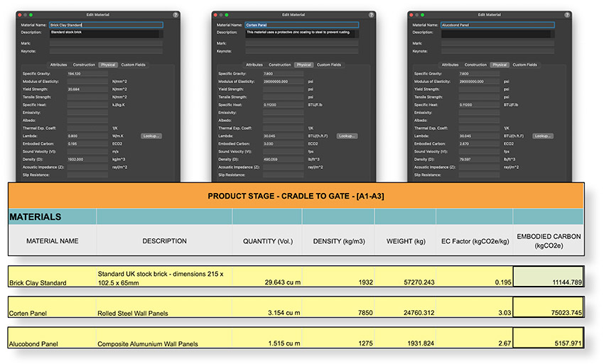
Image courtesy of Vectorworks
Vectorworks Embodied Carbon Calculator. Different types of facade material with relevant data can be analyzed within a BIM program to determine the optimal choice to reduce the building’s carbon footprint.
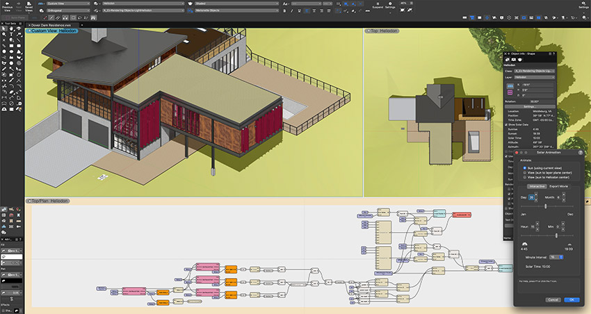
Image courtesy of Vectorworks
Sun shading systems can be analyzed within a BIM program to determine the most effective approach to reduce solar heat gain.
BIM and Carbon Emission Calculations
Part of designing more sustainable facades and buildings including an environmental or carbon assessment of the products, materials, and systems that are selected as part of the design.
Through the use of BIM software and other tools, data can be assigned to each component of the building based on published data from a manufacturer’s EPD. For instance, one can use material resources representing specific building materials to support an effective BIM workflow. These act as a receptacle for a wide range of information, like graphic attributes such as fill or texture, but also real-world physical attributes such as gravity, yield strength, tensile strength, density, embodied carbon, and other data that can be found in a product’s environmental product declaration (EPD). All this data within the material resource can be used to create accurate reports and data visualization diagrams. Each facade design can then be compared based on this data to more accurately determine global warming potential and embodied carbon values related to the materials used in each design scheme. This is ultimately most helpful in making informed decisions when evaluating different materials in a design and determining any required changes to reduce a building’s environmental impact.
The iterative design process based on its embodied carbon can be as simple as comparing the exterior wall system with various types of facade systems where the needed data has already been assigned to the materials in those facade types. When presented and compared, the data can ultimately speak for itself allowing designers to weigh in on the related pros and cons of cost, availability, or other factors. In this way, composite aluminum panels, for example, can be assessed as an alternative to more traditional materials like clay brick or even steel sheets. Some BIM software includes an integrated energy performance analysis tool which allows designers to assess energy performance in the early stages of the design (not needing to wait until later in the design process) and evaluate the building’s operational carbon right up front where it is easy to adjust the design as may be needed.
Relatedly, flexible design tools like BIM software support architects in their process of innovative thinking. It has been noted already that implementing sun shading systems is an effective practice for reducing solar heat gain and improving sustainable design. Customizing and automating the design of these systems can help to optimize a building’s energy consumption. Using tools based on algorithms-aided design (AAD), virtually endless opportunities are possible for design customization and analysis. For example, with algorithmic modeling, a designer can connect a sun shading element to real sun positions so that its orientation can respond to change throughout the day. This interaction allows for an accurate interpretation and analysis of sun shading studies focused on optimizing a facade design.
BIOPHILIC FACADES
Biophilic design is a design philosophy centered around connecting people with nature within built environments and communities. It has been applied to building interiors and exteriors and can be applied to building facades as well. There are a growing number of designs where the exterior wall is intentionally covered with living plant growth of various types providing a number of beneficial sustainability attributes. First, a “green wall” as it can be called, provides a natural means of shading a building from excess sunlight and heat, thus reducing cooling loads and the related energy use. Second, such a green facade can help to reduce the urban heat island (UHI) effect – a phenomenon observed when pavement, roofing, and other dark surfaces absorb sunlight and create islands of heated air in an urban environment. Green walls thus become an excellent alternative for building facades in urban developments. Third, green facades, particularly if used in conjunction with green roofs, can also assist with water management, absorbing and containing water, thus reducing potentially damaging stormwater runoff. Finally, green facades absorb carbon dioxide as part of the natural process of photosynthesis. This reduces the amount of carbon in the atmosphere and replaces it with plant-generated oxygen. Beyond the physical attributes, green facades, like other biophilic design techniques, have some positive health and wellness benefits too. Biophilia has been shown to promote calmness and boost creativity in different settings.
Images courtesy of Vectorworks
Modeled Green Wall Symbol. Different types of green wall systems with relevant material data can be analyzed within a BIM program to determine the best overall choice.
Creating a green facade means coordinating the component elements such as metal accents and connections to facade structures. Some use lattice-type structures applied over the exterior of the building and are planted in the ground below. Thus, they require little to no soil since the plants creep up the wall or building along the lattice. Other systems rely on the use of modular tiles and trays that provide a structure for plants and soil. Such structures require a means of irrigation and ample space for the plant roots in which to live.
Any of these strategies for a green facade can all be designed effectively as part of a BIM process. Flexible BIM software with integrated, freeform 3D modeling tools allows designers to create and visualize such systems, similar to other facade systems. Hybrid BIM symbols contain both 3D objects and 2D graphics, which make it easy to visualize and create the required green wall structure and corresponding documentation. A BIM symbol may contain any 3D shape, specific plant objects, image props, and even foliage to help visualize the proposed system. In some programs, a tool specifically for foliage allows the creation of 3D foliage by drawing polylines or closed 3D shapes and has different options for the density of leaves and leaf type. The power of BIM in this case also allows for data to be attached to these symbols to help calculate the environmental impact (i.e., benefits) of the system.
FACADE EXPANSION JOINT SYSTEMS
As discussed already, large buildings will need expansion joints and those joints will need to be covered to keep the facade protected against weather and the elements. Therefore, once the engineer has determined the locations it is then typically up to the architect to select the expansion joint material and the means to cover or seal that joint. What is the best solution? The answer depends on the building and the conditions that it is subjected to. Caulking or sealant may be all that’s necessary for 1 inch or narrower joints with only a little lateral movement, but wider joints need a fully coordinated system. Compressible fillers are common and made from different types of foams that are secured into the joint. Others use bellows, blankets, or tough pleated rubber systems to fill the gap that can bend and move with the adjacent building structure. Metal architectural joint cover systems are usually the preferred choice to cover over expansion joints since they can be selected to meet a variety of criteria. They can move with the joint to absorb different types and amounts of building movement, be attached readily into the structure, and address fire code concerns. Architecturally, they can be finished on the outside with materials that match or are compatible with the finish and color of adjacent facade surfaces.
Matthew Fisher is the Senior Product Manager, JointMaster Division, of Inpro. He sees the issues associated with expansion joints on a daily basis and notes, “No one likes to deal with expansion joints, however, one of my favorite sayings is: If you don’t address expansion joints properly, Mother Nature will install one free of charge─and it will likely be less attractive and leakier than any of the intentionally designed options.
In light of all of the above, we take a closer look at some different types of expansion joint systems in the following sections.
Images courtesy of Inpro
Metal expansion joint cover systems are available to allow for a full range of material types to be inserted so as to blend with the surrounding facade.
Metal Cover Plate Systems
While compressible foam or rubber cover systems will work just fine in some cases, there are cases where a metal system is called for in order to achieve the strength and durability needed. This is especially true on facades that are exposed to all types of weather conditions. In addition, metal cover plate systems should always be used for joints 6” or wider since other types will not likely perform as well over time. In addition to the durability of the cover system, a wide range of accessories can be added in any combination behind the cover to address thermal control, noise dampening, and water resistance as well.
Some things to consider when specifying metal expansion joint systems include the following:
- Quality Control reporting should be provided based on ASTM E1399 “Standard Test Method for Cyclic Movement and Measuring the Minimum and Maximum Joint Widths of Architectural Joint Systems.”
- If metal-based systems are used to cover the joint, they need to demonstrate durability and impact resistance. Composite panels (aka sandwich panels) offer a lightweight material that’s easy to fabricate using ordinary wood and metalworking tools.
- The joint system should accommodate common architectural fastening systems and be suitable for the facade type whether a curtain wall facade, rainscreen system, or other architectural cladding solutions.
- The amount of movement the cover plate should allow for needs to coordinate with the Structural Engineer's requirements- including seismic and lateral shear capable conditions. Note that it is highly suggested to steer engineers away from a full 100 percent (+/-) joint movement. Doing so means they are intentionally designing the structures to close completely together- down to 0", which would effectively crush any fire, water, or other components within the throat of the joint. Instead, challenge the engineers to leave at least 2-3 inches [50-75mm] at maximum closure to maintain the integrity of the systems, even though this means the joint will be slightly wider. A slightly wider joint solution is actually more cost-effective than the alternative systems that need to be deployed when 100 percent (+/-) is requested.
- The expansion joint system should readily conform to complex geometries including parapets, soffits, and other changes in direction on a facade through the use of clearly depicted transitions via isometric details. These can be sourced free of charge by reputable manufacturers for inclusion in contract documents.
- In terms of the finish of the cover plate system, it is common to specify architectural grade weather and fade-resistant resin (Fluoropolymer) color coatings over metal meeting AAMA 2605 requirements. A range of standard and custom colors are available from most manufacturers.
- For other types of finishes, a system that is adaptable to a range of infill options such as stone, tile, or stucco can be specified.
- Exposed fasteners should be avoided in most cases for appearance as well as for safety.
There are other details that can be considered in selecting expansion joint systems too, including the way the cover is engaged. Some systems have tight movement tolerances while others allow for generous day-to-day or seasonal changes without any true activation or resealing required. When a seismic event or dynamic movement is encountered, expansion joint covers are designed to survive the movement pattern. However much like every other system within the building, inspection and reset may be required.
Images courtesy of Inpro
Metal expansion joint cover systems should be specified to meet the needs of a specific building facade and the conditions it is exposed to.
System Coordination
If an expansion joint is needed on a facade, it very likely needs to continue across the roof and other adjacent planes of the building as well. It is often the points of transition like these that are the source of problems and failure of the system─meaning air and water leakage potential, fire breaching, etc. Therefore, the ideal situation is to select a system that is already designed and manufactured to make the transition so a properly sealed, continuous joint cover system can be installed. It is of course also very helpful to have the manufacturer provide a full complement of CAD and BIM files so the details of the expansion joint system can be worked directly into the facade design and properly coordinated with other materials and systems.
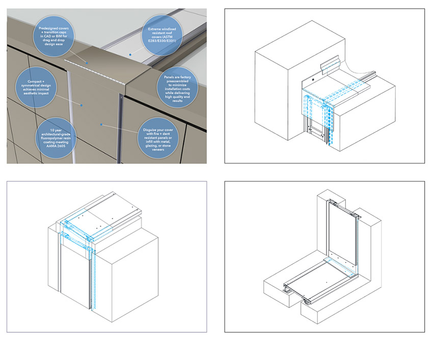
In order to address this need, there are new products available that include coordinated wall and roof expansion joint systems with pre-designed transition caps for all types of changes in joint direction. Since both the wall and roof systems are designed and manufactured together, they work well in the field together too. This is a significant improvement over the traditional industry approach of matching the wall expansion joint with a dissimilar system on the roof. Installing two very different expansion joint systems on a building ultimately makes addressing all the changes in planes more difficult and usually requires project-specific solutions each time. A coordinated, modular-based manufactured system can wrap up, over, around, and back down the entire facade and roof with one continuous system that makes design implementation much easier. It is also possible to pre-assemble the covers to the greatest degree possible such that the installation is also simplified resembling simply hanging a door on its hinges. This approach also ensures repeatable results in quality, consistency of substrate requirements, a distinct reduction of field labor costs, and reduced time for workers on roof edge conditions or on scaffolding. A range of high-performance waterproof membranes can be coupled with this adaptable system such as insulated moisture barriers (for moisture and thermal control), reinforced, two-ply, 45-mm-thick EPDM sheets, (weather protection only), or flexible TPO or PVC membranes (for chemical compatibility with adjacent skins).
Images courtesy of Inpro
A coordinated expansion joint system that can transition seamlessly from facades to roofs and other adjacent surfaces can reduce the potential for problems or failures at the transition points.
Fire-Resistive Joint Systems
In many cases, expansion joints are installed in construction that need to maintain a fire-resistive rating across the joint. Since building expansion joints in floors, roofs, or walls create a pathway for fire and smoke to travel through, it is useful to recognize that a range of third-party tested joint solutions are available.
Expansion joints are tested under a rigorous three-tier testing classification called UL2079 - Test for Fire Resistance of Building Joint Systems. This encapsulates the burn characteristics of ASTM E119 (Surface burning) and the joint cycling of ASTM E1399 in a similar fashion to E1966 and is immediately followed by a hose-stream test for any vertical applications. These tests are designed to essentially replicate a seismic event with ground shaking (cycle test), broken gas lines, and electrical fire (oven burn, 120, or 180 minutes at 2,000°F) then control of the fire (hose stream test). If at any point during this testing, flames escape through the joint product, or if the temperature climbs too much, or if any smoke whatsoever makes its way through, then the product fails. Period. In order to pass, the manufacturer needs to re-design and re-test the product until it passes.
Beyond basic product testing, the International Building Code (IBC) references the need for entire facade assemblies that use combustible elements to show additional fire resistance following NFPA 285 “Standard Fire Test Method for Evaluation of Fire Propagation Characteristics of Exterior Wall Assemblies Containing Combustible Components.” This standard looks at the entire wall assembly, not just individual products for code compliance, and it was developed in response to building fires where combustible foam insulation was used in the facade design.
Note that there are three fundamental types of fire-rated joint systems. The first is to use compressible foam products that have been shown to achieve appropriate fire ratings. A manufactured fire-rated pre-compressed foam material that is totally impregnated with fire retardant will maintain the specified and tested fire-rated assembly even if the facing has been damaged. Another option is mineral wool and intumescent sealants, which are extremely simple to install and very cost-effective. However, they can only be deployed on narrow joints of 1-3" [25-75mm] and only allow for 20 percent (+/-) joint movement. A third fire-resistive product is based on the use of fire blankets. These are the most versatile systems, suitable for expansion joint gaps of 2 through 32 inches and able to withstand high rates of movement. Fire blanket systems come in two forms—either ceramic cloths with intumescent layering or graphite sheet goods encasing insulating blankets. In seismic conditions, they allow for approximately 50 percent (+/-) of joint compression and expansion movement. Some models are able to retain their rating through lateral shear movement testing while others cannot. Fire blankets are tested in concrete on horizontal decks; however, any tested and rated fire-rated deck assembly is acceptable as the joint only addresses gap protection. Walls are typically tested in steel studs and Type X gypsum, however similarly to the floors, any properly rated wall system (CMU, shaft walls, etc.) is acceptable.
Note that fire blankets can be specified either to withstand water or not. Those that cannot withstand water exposure and become wet are often rendered useless against smoke, fire, and heat - even after re-drying they carry diminished fire resistance. Products that are rated and tested for water exposure during or after construction or for open structures such as parking facilities and stadiums, provide fire protection even if they become wet. It is important then, to select and specify the appropriate material for the water conditions anticipated in the building.
CONCLUSION
Facades require design attention at the large scale and the detail level. That includes everything from the materials used, the approach taken to sustainability, the incorporation of expansion joints where needed, and the coordination of the facade design with other building planes. Expansion joints in particular require an understanding of the forces and conditions that need to be addressed as well as information related to available products and systems just like other components of the facade. Using BIM has been shown to be a very helpful and effective means to address the need for the design and coordination of facade elements. Of course, the strategies, features, and ideas presented here behind using BIM as a tool for designing a facade are certainly not all-inclusive. There are clearly many other advantages and opportunities that BIM tools can provide in developing, implementing, and creating better facades that are integrated, efficient, and sustainable. The combination of physical data with the visualization of component parts and the integration of the whole design for sustainability purposes is the launch pad for creating better building designs and more successful facade designs.
Peter J. Arsenault, FAIA, NCARB, LEED AP is a nationally known architect and a prolific author advancing better building performance through better design. www.pjaarch.com, www.linkedin.com/in/pjaarch
On all buildings, the outer skin (e.g., the facade) performs all of the same functions that the skin on our body does. In both cases, it is the skin that protects the inside from the elements like sun, rain, and wind. It regulates the flow of moisture by allowing it to permeate through the skin when needed or prevent it from passing at other times. It helps regulate our temperature in conjunction with insulating layers. It absorbs or reflects light and heat based on the color and texture. In some cases, it can be self-healing or otherwise easy to repair when damaged. And, of course, we want it to look good and healthy not just today but over many years. In this course, we address these multiple aspects of building skins including their role in creating sustainable buildings. While the part we see is the outer surface of the facade, buildings like people, are much more than just skin deep.
Photo courtesy of Low Hammond Rowe Architects
Dallas Road Townhouses. Building facades come in all types, styles, shapes, and sizes, yet they all need to be designed well for reasons of aesthetics, safety, sustainability, and overall performance.
SUSTAINABLE FACADE DESIGN
Facade design is part of every building project. The style, character, and visual appeal of a building are all part of the design considerations. In addition, the performance in terms of energy flows, water control, moisture management, and impact on the surrounding environment all come into play too. Most facades are a combination of opaque wall areas and fenestration, each with their own contributions, or detractions, from the appearance and performance of a facade.
A primary design requirement from building owners, building codes, and voluntary standards is that the facade must meet criteria for sustainability and resilience. Doing so is a multi-step process with many different, sometimes competing, considerations. Fortunately, things have evolved to the point where aesthetics and sustainable performance can be blended into a complementary and successful solution. The application of continuous insulation over a structural system of whatever type is becoming more common and readily achievable to produce higher thermal performance in most climate zones across the US and Canada. Air and water barrier products are more plentiful with more options for application types to effectively control air infiltration and manage vapor transmission. Cladding and rain screens have become well developed including some sophisticated means for supporting them. All of these components go into a facade design, so understanding not only their purpose, but also their material makeup plays directly into creating a sustainable facade.
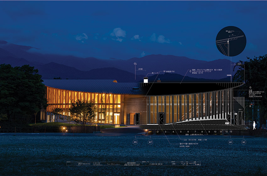
Images courtesy of Habit Studio
Falkland Street Project. BIM software allows designers to visualize different building designs while providing data related to performance and sustainability.
Design Strategies
Architects and other building design professionals seeking to achieve sustainable facades can learn from some strategies that have been successfully used by others including the following.
- Consider Lightweight Cladding: Less weight usually translates into less structure to hold it up─not only in the framing but also in the foundation. In particular, the use of lightweight metal in facades can include rolled steel sheets, metal cladding panels, or composite metal panels. Metal building products, such as steel and aluminum, typically contain high amounts of recycled material thus lowering the amount of embodied carbon in the products. Masonry and concrete or other cement-based products are fossil fuel intensive to produce with high levels of embodied carbon. Metal fabrication can have even lower carbon footprints when the electricity used in the process comes from renewable resources like wind, solar, or hydropower. Finally, the ability to recycle and upcycle metal materials at the end of their service life also improves their sustainability.
- Prioritize Adaptive Reuse or Historic Preservation: It is often said that the most sustainable building is an existing one. The same is true of facades. If a building renovation project includes facade work, focus first on the ability to save and re-use what is there before automatically assuming everything has to be removed and done over. This could include selectively removing only things that are outdated or deteriorated but keeping the things that are still usable while their replacement would create more work, and more emissions, to produce and install.
- Account for Siting and Building Orientation: Facade skins can always get a little help from their surroundings. Siting and building orientation play a big role in the amount of wind, sun, and weather that a building facade is exposed to─and it may be different on different sides of a building. Trees and other vegetation can provide some shade and protection while surrounding buildings in an urban setting can do the same thing. In cases where facades are fully exposed, adding elements over fenestration is a common approach to improve shading and overall performance. Strategies can include horizontal or vertical sun shading systems as conditions call for. They can also include planted green facades to add a natural, biophilic solution.
- Anticipate Climate Extremes: Many buildings are being subjected to more extreme conditions than previously due to climate change. The frequency and severity of storms and the intensity of temperature and wind conditions have made historical data alone unreliable as a design guide. Similarly, climate zone designations have been a useful benchmark for climate conditions, but individual sites can have widely varying conditions. Hence, it has become prudent to include measures for increased resistance to these extremes as a means of creating more resilient, and therefore more sustainable, buildings.
The design process of achieving a truly sustainable facade has changed in recent years. It is no longer a matter of just picking a few products out of a catalog and calling it done. Rather, detailed information is needed not only on the technical aspects of the products’ performance but also on their ability to be compatible with other products and with building codes. Similarly, there is a need to have information about the environmental impacts of the products selected which is often found in Environmental Product Declarations (EPDs). Managing all this data can be quite difficult if done manually or in a piecemeal fashion. It is more effective to use computer-based data coordinated with Building Information Modeling (BIM) software. A key advantage of BIM software is that it provides the ability to readily visualize, test, and analyze a variety of different building facade designs in order to arrive at the best outcome. The algorithms and visualization tools inherent in BIM inform design professionals how a specific project will both look and perform in a particular site and in light of the natural elements there. In this way, an integrated planning and design process can be employed to ensure a project is set up for success to meet all project goals, including sustainability, from inception through to completion.
DESIGNING FOR MOVEMENT
The design of facades for larger buildings needs to consider the fact that building structures, and their facades, must be allowed to move. That movement is accommodated by designing predetermined gaps into large structures that can absorb the motion. In large buildings, they are a necessity, particularly where buildings are segmented into different sections or if one attaches to another structure such as a parking garage or other use. The location, size, and movement requirements for all such expansion joints are project-specific and appropriately established by the Structural Engineer of Record.
Some design conditions directly affect the way expansion joints are worked into a building. For example, facades and exterior elements often have complex geometries that can converge in a range of locations such as at grade, under entry portals, at beltlines, across patios, soffits, etc. It is also common that multiple materials are used for aesthetic or functional purposes on a building. All of these conditions directly affect expansion joints, requiring them to accommodate differing materials─to invert under patios, climb up and over parapets or elevator mechanical rooms, negotiate curbs or rooftop gardens, etc. These locations are also where a range of trades can come together for the different materials and systems being installed. Not surprisingly, these locations are also the sources of most leaks or breaches in the envelope related to water, air, or thermal compromises. Therefore, providing properly coordinated details that can be used by the trades to address these situations can be critically important in maintaining the integrity of the facade across the expansion joints and the areas around them.
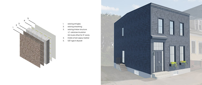
Images courtesy of Habit Studio
Expansion joints in a facade can blend in with the surrounding material or be designed to make a visual statement. Either way, they need to be located and installed properly to address the different types of movement to which a building and facade can be exposed.
Unfortunately, very few projects containing expansion joints are ever detailed to such a finite level. This leaves most contractors, facility managers, owners, and potentially architects to deal with the consequences of uncoordinated expansion joint systems for years to come. Industry data suggests that expansion joint issues account for the second highest recurrence of the owner's first year callbacks to the contractor (The #1 reason remains HVAC balancing problems). The owner’s issues generally surround frustration with joint systems- whether for functional, aesthetic or leak-resistance purposes.
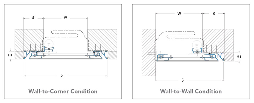
The first step to proper specification and detailing of a joint system is to acknowledge the nominal joint size for a particular building and the range of movement between the fully contracted size and the fully expanded size. The design width of an expansion joint at an average air temperature is referred to as the nominal joint size. The building movement that makes expansion joints necessary occurs due to several common reasons with three types of movement that typically need to be accommodated:
- Thermal Forces: This type of movement is most typical and caused by daily or seasonal environmental temperature changes in and around the structure. Thermal movement is primarily “one-directional” in nature and is the result of the expansion and contraction of structural elements as affected by heat, cold, and humidity levels. The typical amount of thermal movement is approximately 10-25 percent of the nominal joint size. That means the maximum expanded joint size where the building sections contract away from each other (i.e., during cold temperatures) should be 10 – 25 percent more than the nominal joint size. Similarly, the minimum contracted joint size where the building sections expand toward each other (during warm temperatures) should be 10 – 25 percent less than the nominal joint size. If expansion joints aren’t sized and installed properly, then the thermal expansion and contraction can cause buckling of structural surfaces and ripple along the facade and other surfaces.
- Seismic Activity: The shifting of the earth’s tectonic plates (i.e., earthquakes, tremors, etc.), and shifts along fault lines is the source of seismic activity. Seismic movement may be horizontal, vertical, in shear, or a combination of all three. Seismic expansion joint widths may need to increase with higher floor levels to accommodate the additional, cumulative movement that needs to be addressed. These joints must have the capacity for movement of plus or minus 50-100 percent of the nominal joint size associated with them. When it comes to expansion joint systems, it is important to select systems that can “reset” themselves after a minor seismic event without requiring workers to reposition any cover panels.
- Wind-Loads: Movement induced by high winds, can force the structure to sway. This movement is normally perpendicular and/or parallel to the joint. This is common where a low horizontal building span meets with a taller vertical element. Movement in these joints is typically on the order of 50 percent of the joint width. Over time, the near-constant effects of wind pressure on the sides of buildings can lead to serious issues such as aerodynamic instability, torsion or swaying, erosion of certain building materials, and cladding failure due to wind load or impact of debris. In extreme cases, it can lead to structural failure and damage to people and property. Therefore, when designing a structure, it must be able to both withstand high wind loads but also work with them. As with seismic activity, expansion joint systems should be able to “flex” and yet remain in place as the building sways or torques.
A growing concern regarding wind and expansion joints is related to more extreme environmental factors including increasingly higher wind speeds and the uplift/ pull forces they impose on the exteriors of buildings. Increased attention to wind uplift calculations has been occurring in engineering standards such as ASCE 7- “Minimum Design Loads and Associated Criteria for Buildings and Other Structures.” These standards have been changing in response to environmental and climate challenges that have become more intense in recent years. Similarly, California and Florida code research indicates more stringent scrutiny of resistance to extreme weather is being considered during the code plan reviews and architectural shop drawing reviews. This is leading to specifications calling for fully tested expansion joint cover systems that can meet standards such as ASTM E1399 (seismic cyclic movement testing), as well as ASTM E283, ASTM E330, and ASTM E331 (Water, Air, and Structural integrity tests). These are all now required to ensure the specified system will not only perform as intended but also reduce professional liability risk.
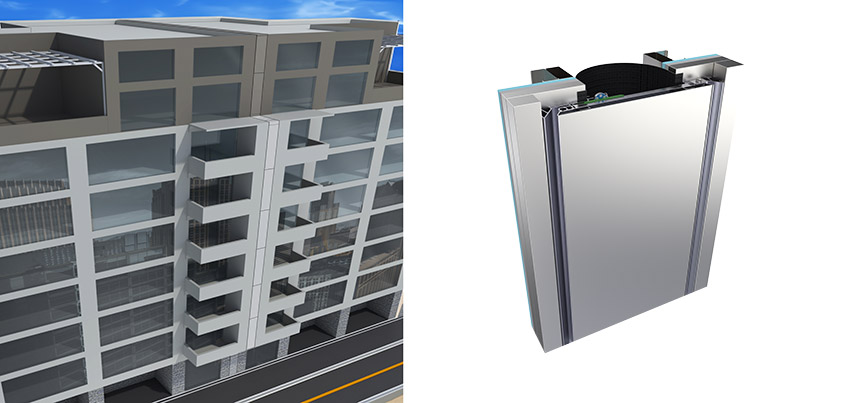
Image courtesy of Vectorworks
Product’s EPD data applied to wall components. Building Information Modeling (BIM) not only helps with the visualization of facades, but it also helps with the performance and sustainability of the building by using integrated data and reporting tools.
By properly addressing all these conditions, the building can be protected from the movement that will invariably occur and avoid the resulting damage that is possible.
Typically, if an expansion joint is needed in a facade, it also needs to run continuously through all adjacent planes to fully separate building sections and allow independent movement. That means that any given project could include interior joints, exterior joints, or both in things like walls, roofs, floors, building veneers, soffits, parking decks, patios, roofing systems, etc.
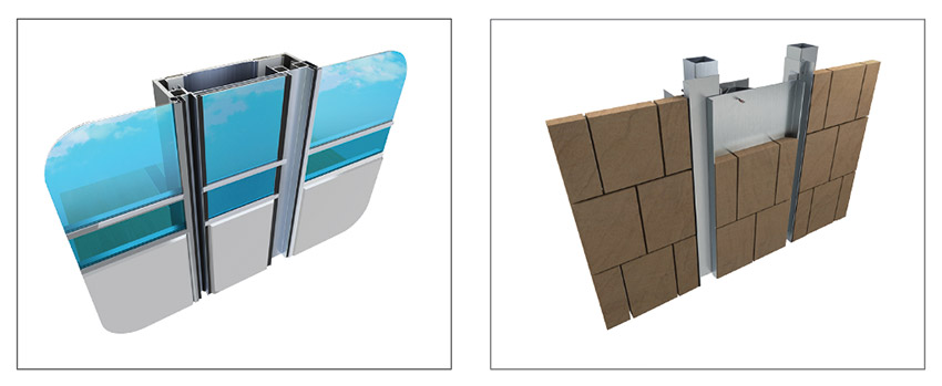
Recognizing the need for functional but aesthetically appropriate expansion joints, several manufacturers carry exterior wall systems that provide a functional system with options to infill a joint cover with material to match or blend with the facade material. These infill options could include but are not limited to metal panels, lightweight or thinned masonry units, EIFS or true stucco, spandrel glazing, and composite metal panels (CMPs). It’s worth noting that newer systems on the market have more overall depth than other systems and provide mechanical attachment points to give the designer and installer the most customization options within a standardized, cost-effective system. If the client chooses to utilize CMPs for their project, there are fire and dent-resistant expansion joint panels available.
USING BIM FOR BETTER FACADE DESIGN
Many architectural firms have embraced the use of Building Information Modeling (BIM) as a better, more coordinated, and more streamlined way to manage the design and construction (or renovation) of a building project. While the benefits of this approach are numerous, we will focus here on how integrated BIM software can greatly enhance facade designs as well by helping architects achieve a project’s optimal appearance and performance.
At the most basic level, BIM software allows architects to visualize how a project will look as well as perform against natural elements. The beauty of using BIM as a design tool is that professionals can quickly iterate different design options, wall assemblies, and material choices to compare the appearance of each and discern which is preferred. Similarly, the performance impact on the building and sustainability goals can be readily reviewed as needed to optimize outcomes. Integrated design tools aided by algorithms can help the design process with automation-enhanced testing of various scenarios. This integrated approach empowers designers to explore the aesthetic design features of a project with real-time rendering using a wide range of materials and textures resources. From a full facade planning standpoint, the software can also provide full visualization of sun paths and create sun studies as part of the design process. This can be invaluable in determining the degree of sun exposure and the appropriate means to address it, either for enhancing daylighting into a building or for shielding it from excessive solar gains.
Using data-driven design tools embedded in BIM objects helps architects make more fully informed design decisions. The data-driven design aspect of BIM software provides the opportunity to test the simulated or comparative performance of different design choices. This is possible because data from a BIM model generated with parametric building objects provides information to designers allowing them to make better design decisions. This can be most fully achieved by using BIM-generated automatic reports, quantity takeoff calculations, and schedules (i.e., room schedules, finish schedules, door and window schedules, etc.).
Colin Davis, of the London-based architectural practice Studio Partington, has been experiencing the benefits of using BIM for design for quite some time. It has helped him and the practice better understand the process of creating well-designed and truly sustainable buildings. He comments, “You don’t design a building that you like the look of and then strap on solar panels on the roof and build up the insulation really high and call it a day.” Using BIM, the firm is able to analyze and assess the data of different parts of the building envelope and readily compare different options to see what really does work and what doesn’t.
Davis also sees the larger value of using BIM for internal use as well as for explaining concepts to others. “I do think the ability to capture information graphically is a really great skill for architects to have,” says Davis, “and it’s often missing from research projects where the data might be great, but people haven’t really thought about how it is communicated.” It is here that Davis notes that the historic strength of BIM in graphics capabilities really shines for a mid-size firm like Studio Partington, where he notes, “Our job as architects ultimately is one of communication.” Part of that communication is in how a building will act or perform, too. “You can develop and test a massing model very quickly in BIM, which has many advantages, like using built-in tools for shadow analysis. So, [for example] the spaces you have labeled as ‘park’ if you see they don’t get much sunlight, you know immediately you must adjust the design.”
Image courtesy of Vectorworks
Vectorworks Embodied Carbon Calculator. Different types of facade material with relevant data can be analyzed within a BIM program to determine the optimal choice to reduce the building’s carbon footprint.
Image courtesy of Vectorworks
Sun shading systems can be analyzed within a BIM program to determine the most effective approach to reduce solar heat gain.
BIM and Carbon Emission Calculations
Part of designing more sustainable facades and buildings including an environmental or carbon assessment of the products, materials, and systems that are selected as part of the design.
Through the use of BIM software and other tools, data can be assigned to each component of the building based on published data from a manufacturer’s EPD. For instance, one can use material resources representing specific building materials to support an effective BIM workflow. These act as a receptacle for a wide range of information, like graphic attributes such as fill or texture, but also real-world physical attributes such as gravity, yield strength, tensile strength, density, embodied carbon, and other data that can be found in a product’s environmental product declaration (EPD). All this data within the material resource can be used to create accurate reports and data visualization diagrams. Each facade design can then be compared based on this data to more accurately determine global warming potential and embodied carbon values related to the materials used in each design scheme. This is ultimately most helpful in making informed decisions when evaluating different materials in a design and determining any required changes to reduce a building’s environmental impact.
The iterative design process based on its embodied carbon can be as simple as comparing the exterior wall system with various types of facade systems where the needed data has already been assigned to the materials in those facade types. When presented and compared, the data can ultimately speak for itself allowing designers to weigh in on the related pros and cons of cost, availability, or other factors. In this way, composite aluminum panels, for example, can be assessed as an alternative to more traditional materials like clay brick or even steel sheets. Some BIM software includes an integrated energy performance analysis tool which allows designers to assess energy performance in the early stages of the design (not needing to wait until later in the design process) and evaluate the building’s operational carbon right up front where it is easy to adjust the design as may be needed.
Relatedly, flexible design tools like BIM software support architects in their process of innovative thinking. It has been noted already that implementing sun shading systems is an effective practice for reducing solar heat gain and improving sustainable design. Customizing and automating the design of these systems can help to optimize a building’s energy consumption. Using tools based on algorithms-aided design (AAD), virtually endless opportunities are possible for design customization and analysis. For example, with algorithmic modeling, a designer can connect a sun shading element to real sun positions so that its orientation can respond to change throughout the day. This interaction allows for an accurate interpretation and analysis of sun shading studies focused on optimizing a facade design.
BIOPHILIC FACADES
Biophilic design is a design philosophy centered around connecting people with nature within built environments and communities. It has been applied to building interiors and exteriors and can be applied to building facades as well. There are a growing number of designs where the exterior wall is intentionally covered with living plant growth of various types providing a number of beneficial sustainability attributes. First, a “green wall” as it can be called, provides a natural means of shading a building from excess sunlight and heat, thus reducing cooling loads and the related energy use. Second, such a green facade can help to reduce the urban heat island (UHI) effect – a phenomenon observed when pavement, roofing, and other dark surfaces absorb sunlight and create islands of heated air in an urban environment. Green walls thus become an excellent alternative for building facades in urban developments. Third, green facades, particularly if used in conjunction with green roofs, can also assist with water management, absorbing and containing water, thus reducing potentially damaging stormwater runoff. Finally, green facades absorb carbon dioxide as part of the natural process of photosynthesis. This reduces the amount of carbon in the atmosphere and replaces it with plant-generated oxygen. Beyond the physical attributes, green facades, like other biophilic design techniques, have some positive health and wellness benefits too. Biophilia has been shown to promote calmness and boost creativity in different settings.
Images courtesy of Vectorworks
Modeled Green Wall Symbol. Different types of green wall systems with relevant material data can be analyzed within a BIM program to determine the best overall choice.
Creating a green facade means coordinating the component elements such as metal accents and connections to facade structures. Some use lattice-type structures applied over the exterior of the building and are planted in the ground below. Thus, they require little to no soil since the plants creep up the wall or building along the lattice. Other systems rely on the use of modular tiles and trays that provide a structure for plants and soil. Such structures require a means of irrigation and ample space for the plant roots in which to live.
Any of these strategies for a green facade can all be designed effectively as part of a BIM process. Flexible BIM software with integrated, freeform 3D modeling tools allows designers to create and visualize such systems, similar to other facade systems. Hybrid BIM symbols contain both 3D objects and 2D graphics, which make it easy to visualize and create the required green wall structure and corresponding documentation. A BIM symbol may contain any 3D shape, specific plant objects, image props, and even foliage to help visualize the proposed system. In some programs, a tool specifically for foliage allows the creation of 3D foliage by drawing polylines or closed 3D shapes and has different options for the density of leaves and leaf type. The power of BIM in this case also allows for data to be attached to these symbols to help calculate the environmental impact (i.e., benefits) of the system.
FACADE EXPANSION JOINT SYSTEMS
As discussed already, large buildings will need expansion joints and those joints will need to be covered to keep the facade protected against weather and the elements. Therefore, once the engineer has determined the locations it is then typically up to the architect to select the expansion joint material and the means to cover or seal that joint. What is the best solution? The answer depends on the building and the conditions that it is subjected to. Caulking or sealant may be all that’s necessary for 1 inch or narrower joints with only a little lateral movement, but wider joints need a fully coordinated system. Compressible fillers are common and made from different types of foams that are secured into the joint. Others use bellows, blankets, or tough pleated rubber systems to fill the gap that can bend and move with the adjacent building structure. Metal architectural joint cover systems are usually the preferred choice to cover over expansion joints since they can be selected to meet a variety of criteria. They can move with the joint to absorb different types and amounts of building movement, be attached readily into the structure, and address fire code concerns. Architecturally, they can be finished on the outside with materials that match or are compatible with the finish and color of adjacent facade surfaces.
Matthew Fisher is the Senior Product Manager, JointMaster Division, of Inpro. He sees the issues associated with expansion joints on a daily basis and notes, “No one likes to deal with expansion joints, however, one of my favorite sayings is: If you don’t address expansion joints properly, Mother Nature will install one free of charge─and it will likely be less attractive and leakier than any of the intentionally designed options.
In light of all of the above, we take a closer look at some different types of expansion joint systems in the following sections.
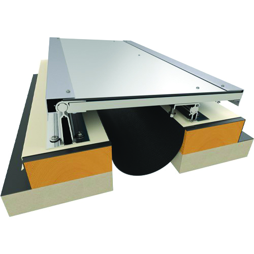
Images courtesy of Inpro
Metal expansion joint cover systems are available to allow for a full range of material types to be inserted so as to blend with the surrounding facade.
Metal Cover Plate Systems
While compressible foam or rubber cover systems will work just fine in some cases, there are cases where a metal system is called for in order to achieve the strength and durability needed. This is especially true on facades that are exposed to all types of weather conditions. In addition, metal cover plate systems should always be used for joints 6” or wider since other types will not likely perform as well over time. In addition to the durability of the cover system, a wide range of accessories can be added in any combination behind the cover to address thermal control, noise dampening, and water resistance as well.
Some things to consider when specifying metal expansion joint systems include the following:
- Quality Control reporting should be provided based on ASTM E1399 “Standard Test Method for Cyclic Movement and Measuring the Minimum and Maximum Joint Widths of Architectural Joint Systems.”
- If metal-based systems are used to cover the joint, they need to demonstrate durability and impact resistance. Composite panels (aka sandwich panels) offer a lightweight material that’s easy to fabricate using ordinary wood and metalworking tools.
- The joint system should accommodate common architectural fastening systems and be suitable for the facade type whether a curtain wall facade, rainscreen system, or other architectural cladding solutions.
- The amount of movement the cover plate should allow for needs to coordinate with the Structural Engineer's requirements- including seismic and lateral shear capable conditions. Note that it is highly suggested to steer engineers away from a full 100 percent (+/-) joint movement. Doing so means they are intentionally designing the structures to close completely together- down to 0", which would effectively crush any fire, water, or other components within the throat of the joint. Instead, challenge the engineers to leave at least 2-3 inches [50-75mm] at maximum closure to maintain the integrity of the systems, even though this means the joint will be slightly wider. A slightly wider joint solution is actually more cost-effective than the alternative systems that need to be deployed when 100 percent (+/-) is requested.
- The expansion joint system should readily conform to complex geometries including parapets, soffits, and other changes in direction on a facade through the use of clearly depicted transitions via isometric details. These can be sourced free of charge by reputable manufacturers for inclusion in contract documents.
- In terms of the finish of the cover plate system, it is common to specify architectural grade weather and fade-resistant resin (Fluoropolymer) color coatings over metal meeting AAMA 2605 requirements. A range of standard and custom colors are available from most manufacturers.
- For other types of finishes, a system that is adaptable to a range of infill options such as stone, tile, or stucco can be specified.
- Exposed fasteners should be avoided in most cases for appearance as well as for safety.
There are other details that can be considered in selecting expansion joint systems too, including the way the cover is engaged. Some systems have tight movement tolerances while others allow for generous day-to-day or seasonal changes without any true activation or resealing required. When a seismic event or dynamic movement is encountered, expansion joint covers are designed to survive the movement pattern. However much like every other system within the building, inspection and reset may be required.
Images courtesy of Inpro
Metal expansion joint cover systems should be specified to meet the needs of a specific building facade and the conditions it is exposed to.
System Coordination
If an expansion joint is needed on a facade, it very likely needs to continue across the roof and other adjacent planes of the building as well. It is often the points of transition like these that are the source of problems and failure of the system─meaning air and water leakage potential, fire breaching, etc. Therefore, the ideal situation is to select a system that is already designed and manufactured to make the transition so a properly sealed, continuous joint cover system can be installed. It is of course also very helpful to have the manufacturer provide a full complement of CAD and BIM files so the details of the expansion joint system can be worked directly into the facade design and properly coordinated with other materials and systems.
In order to address this need, there are new products available that include coordinated wall and roof expansion joint systems with pre-designed transition caps for all types of changes in joint direction. Since both the wall and roof systems are designed and manufactured together, they work well in the field together too. This is a significant improvement over the traditional industry approach of matching the wall expansion joint with a dissimilar system on the roof. Installing two very different expansion joint systems on a building ultimately makes addressing all the changes in planes more difficult and usually requires project-specific solutions each time. A coordinated, modular-based manufactured system can wrap up, over, around, and back down the entire facade and roof with one continuous system that makes design implementation much easier. It is also possible to pre-assemble the covers to the greatest degree possible such that the installation is also simplified resembling simply hanging a door on its hinges. This approach also ensures repeatable results in quality, consistency of substrate requirements, a distinct reduction of field labor costs, and reduced time for workers on roof edge conditions or on scaffolding. A range of high-performance waterproof membranes can be coupled with this adaptable system such as insulated moisture barriers (for moisture and thermal control), reinforced, two-ply, 45-mm-thick EPDM sheets, (weather protection only), or flexible TPO or PVC membranes (for chemical compatibility with adjacent skins).
Images courtesy of Inpro
A coordinated expansion joint system that can transition seamlessly from facades to roofs and other adjacent surfaces can reduce the potential for problems or failures at the transition points.
Fire-Resistive Joint Systems
In many cases, expansion joints are installed in construction that need to maintain a fire-resistive rating across the joint. Since building expansion joints in floors, roofs, or walls create a pathway for fire and smoke to travel through, it is useful to recognize that a range of third-party tested joint solutions are available.
Expansion joints are tested under a rigorous three-tier testing classification called UL2079 - Test for Fire Resistance of Building Joint Systems. This encapsulates the burn characteristics of ASTM E119 (Surface burning) and the joint cycling of ASTM E1399 in a similar fashion to E1966 and is immediately followed by a hose-stream test for any vertical applications. These tests are designed to essentially replicate a seismic event with ground shaking (cycle test), broken gas lines, and electrical fire (oven burn, 120, or 180 minutes at 2,000°F) then control of the fire (hose stream test). If at any point during this testing, flames escape through the joint product, or if the temperature climbs too much, or if any smoke whatsoever makes its way through, then the product fails. Period. In order to pass, the manufacturer needs to re-design and re-test the product until it passes.
Beyond basic product testing, the International Building Code (IBC) references the need for entire facade assemblies that use combustible elements to show additional fire resistance following NFPA 285 “Standard Fire Test Method for Evaluation of Fire Propagation Characteristics of Exterior Wall Assemblies Containing Combustible Components.” This standard looks at the entire wall assembly, not just individual products for code compliance, and it was developed in response to building fires where combustible foam insulation was used in the facade design.
Note that there are three fundamental types of fire-rated joint systems. The first is to use compressible foam products that have been shown to achieve appropriate fire ratings. A manufactured fire-rated pre-compressed foam material that is totally impregnated with fire retardant will maintain the specified and tested fire-rated assembly even if the facing has been damaged. Another option is mineral wool and intumescent sealants, which are extremely simple to install and very cost-effective. However, they can only be deployed on narrow joints of 1-3" [25-75mm] and only allow for 20 percent (+/-) joint movement. A third fire-resistive product is based on the use of fire blankets. These are the most versatile systems, suitable for expansion joint gaps of 2 through 32 inches and able to withstand high rates of movement. Fire blanket systems come in two forms—either ceramic cloths with intumescent layering or graphite sheet goods encasing insulating blankets. In seismic conditions, they allow for approximately 50 percent (+/-) of joint compression and expansion movement. Some models are able to retain their rating through lateral shear movement testing while others cannot. Fire blankets are tested in concrete on horizontal decks; however, any tested and rated fire-rated deck assembly is acceptable as the joint only addresses gap protection. Walls are typically tested in steel studs and Type X gypsum, however similarly to the floors, any properly rated wall system (CMU, shaft walls, etc.) is acceptable.
Note that fire blankets can be specified either to withstand water or not. Those that cannot withstand water exposure and become wet are often rendered useless against smoke, fire, and heat - even after re-drying they carry diminished fire resistance. Products that are rated and tested for water exposure during or after construction or for open structures such as parking facilities and stadiums, provide fire protection even if they become wet. It is important then, to select and specify the appropriate material for the water conditions anticipated in the building.
CONCLUSION
Facades require design attention at the large scale and the detail level. That includes everything from the materials used, the approach taken to sustainability, the incorporation of expansion joints where needed, and the coordination of the facade design with other building planes. Expansion joints in particular require an understanding of the forces and conditions that need to be addressed as well as information related to available products and systems just like other components of the facade. Using BIM has been shown to be a very helpful and effective means to address the need for the design and coordination of facade elements. Of course, the strategies, features, and ideas presented here behind using BIM as a tool for designing a facade are certainly not all-inclusive. There are clearly many other advantages and opportunities that BIM tools can provide in developing, implementing, and creating better facades that are integrated, efficient, and sustainable. The combination of physical data with the visualization of component parts and the integration of the whole design for sustainability purposes is the launch pad for creating better building designs and more successful facade designs.
Peter J. Arsenault, FAIA, NCARB, LEED AP is a nationally known architect and a prolific author advancing better building performance through better design. www.pjaarch.com, www.linkedin.com/in/pjaarch