Factory vs. Field
Architects should understand how and why to consider and specify for factory versus field mulled window assemblies. Factory mulled windows are often considered ideal because the factory approach usually ensures that each window unit is joined together with precision, resulting in consistent sizing, alignment, and performance. This is especially important when creating larger window units, where any inconsistencies could result in air leaks, water infiltration, or other issues. There is also generally greater quality control since the manufacturer can check that each window unit meets its specifications before it is shipped. Choosing factory mulling can also provide greater warranty protection since the manufacturer is responsible for the entire window unit, including the mullion joint. And that warranty can provide peace of mind for both the homeowner and the contractor. In addition, factory mulling can save time and labor costs since the window units are already pre-assembled and ready to install.
Field mulling often faces challenges with weather conditions, materials, and lack of assembly stations. That being said, field mulling can be a viable option in certain situations such as when working with unique or custom window configurations that are harder to achieve through factory mulling. It may also be preferred and necessary with some big-glass designs in situations where projects must ship in sub-assemblies and transportation or accessibility to the job site is a concern. Some companies now offer options for quick on-site assembly by delivering large factory-mulled sub-assemblies, with all necessary components and instructions included, so that contractors have a much easier, faster assembly prep kit that results in an AAMA-450-certified window assembly. This type of assembly solution can help speed construction timelines by incorporating all of the necessary fasteners, clips, caps, and other parts—which reduces specifying time and the risk of missing parts and lost time at the jobsite.
AAMA 450
American Architectural Manufacturers Association (AAMA) 450 is the certification standard for the testing and rating of windows, doors, and skylights. It is useful to both engineers and manufacturers and makes compliance of mulled systems easier and more effective. Specifically, it is a performance standard for the thermal transmittance (U-factor) of fenestration products— how well a window, door, or skylight prevents heat from escaping a building. The lower the U-factor, the better the insulation value of the fenestration product. AAMA 450 sets performance requirements for U-factors for various types of fenestration products under different test conditions.
Mulled assemblies that are not built or tested to meet this standard may not meet performance expectations. Especially in extreme weather conditions and in particular locales, such as coastal regions, underperformance can be a hazard to the safety of building occupants.
Originally published in 2000 as AAMA 450-00, Voluntary Performance Rating Method for Mulled Fenestration Assemblies, the document defined procedures for arriving at a meaningful design pressure (DP) rating from which air, water, and structural performance of mulled assemblies could be more effectively assessed. The standard has been updated since, including in response to major events like the 2004 and 2005 hurricane seasons, when the U.S. experienced a series of severe storms. Hurricanes Charley, Frances, Ivan, and Jeanne caused a combined $62.2 billion in damage and resulted in 123 deaths in 2004. In 2005, a total of 28 named storms hit the U.S., including most notably Hurricane Katrina, which devastated the city of New Orleans, caused more than $125 billion in damage, and resulted in over 1,800 deaths.
AAMA 450 offers three options for determining the overall DP rating of a mulled fenestration system, which is the lower design pressure achieved by either an individual product or by the mulled system, as determined by testing, calculation, or a combination of the two.
The first option tests the total system configuration, which must meet the minimum performance levels for air leakage, water resistance, and uniform load as outlined in the North American Fenestration Standard (NAFS). The second option tests the mullion elements of individual components using a simple beam concentrated load test with the load applied at the center span. Deflection under the load and permanent deflection after the load removal are recorded and must be less than L/175. The third option allows for structural calculations which must follow the procedures stated in Engineering Design Rules set forth by the Fenestration and Glazing Industry Alliance (FGIA)/AAMA 2502-19. Those calculations include:
- Area moment of inertia, bending moments, and section modulus of the mullion element
- Deflection of the mullion element (not to exceed L/175 for spans of 13 feet, 6 inches or less and L/240 + ¼-inch for spans more than 13 feet, 6 inches at the given design pressure)
- Extreme fiber stress (structurally calculated)
AAMA 450-20 Update
In January 2021, FGIA announced an update to the mulled assemblies document. AAMA 450-20, renamed the standard as “Performance Rating Method for Mulled Combination Assemblies, Composite Units, and Other Mulled Fenestration Systems.” It describes test procedures and calculation procedures for determining the performance of mulled fenestration systems for both factory-assembled or field assembly with parts and instructions supplied by the fenestration product manufacturer. Changes and additions have been made to deflection limits, connection strength, load application, and the anchorage of mullion elements.
One particularly notable change is with composite units, which have been brought fully into the scope of the standard, together with storefront and curtainwall fenestration products and side-hinged doors. (A composite unit indicates two or more independent fenestration units, each of which must meet appropriate NAFS requirements, utilizing integral mullions within a single continuous outer main frame.)
With so many different available configurations of mulled fenestration systems, analysis and testing can be overwhelming. For that reason, a key component of AAMA 450 is the allowance of “product grouping” for the purpose of qualifying multiple designs with a single test or evaluation. While other published methods, such as AAMA 2502-19, Comparative Analysis Procedure for Window and Door Products, allow rating of untested sizes, AAMA 450-20 allows rating of untested configurations. The product group can include several different types of operating windows of different performance classes that are combined in a variety of ways using the same mullion profile. One test may qualify all possible combinations of the window types based on the weakest configuration.
Wind-load Calculations for Mulled Assemblies
We all understand that windows are one of the most vulnerable parts of a building when it comes to wind damage. When wind strikes a building, it creates a pressure differential on the building envelope that can cause windows to break or even be blown out of their frames, posing a safety hazard and potential for significant damage to the building and its contents.
Mulled window assemblies are particularly susceptible to wind damage because they create larger surface areas for the wind to act upon. The wind load on a mulled window assembly is greater than that on a single window unit, and the assembly may also have weaker points at the mullions where the units are joined together.
Understanding wind load for mulled window assemblies allows architects and engineers to design window systems that can withstand the forces of wind and protect the building and its occupants. By calculating the wind load on the windows and specifying windows that meet the necessary wind-load rating, architects can ensure that the windows are strong enough to resist the forces of wind and prevent damage or injury. Additionally, proper installation techniques and detailing, such as using appropriate framing and mullion design, can further increase the strength of the window system and reduce the risk of wind damage.
Mulled window assemblies may require additional structure in situations where the expected wind loads exceed the capacity of the window system to withstand them. This can occur in areas that are prone to high winds or in buildings with large window openings that are exposed to wind. One situation where additional structure may be required is when the wind loads exceed the design pressure rating of the windows. In this case, the window system may need to be reinforced with additional framing, such as steel or wood bracing, to increase its strength and rigidity.
How might an architect detect that a mulled window assembly needs additional structure? As a general rule, if the assembly creates a 3-way or 4-way intersection and it exceeds 6 feet in any one direction, additional structure is necessary. Other considerations for determining if additional structure is required would be looking at project site location in terms of terrain and region type. For instance, if the project is in a coastal region or Tornado Alley, it is clearly more susceptible to wind-load issues. And it is also more susceptible if it is on a hill or bluff, in an open field, or next to any body of water, not just oceanside.
Architects must also consider the type of building. High-rise buildings and commercial buildings with large storefronts or curtain walls tend to require additional structure. But as big-glass designs for residential homes become more prevalent, architects will need to be ever more aware of additional durability considerations for window assemblies.
Once it is determined that additional structure is necessary, architects should consult with structural engineers or other licensed design professionals to perform a wind-load calculation and analysis. Structural engineers use specialized software and engineering principles to calculate the expected wind loads on a building based on factors such as the building's location, height, and design. Architects will need to supply the project site address, building elevation drawings, and window assembly size.
The Project Site Address
The project site address will determine the location wind speeds, which will be entered into the calculator. Location wind speeds are based on the specific geographic location of the building or structure. This information is typically obtained from the ASCE 7 standard, which provides detailed information on the wind speed maps for the U.S. and other countries.
The ASCE 7 standard provides wind speed maps that divide the U.S. into zones based on the likelihood of encountering high winds. These maps are based on historical weather data and other factors, such as topography and surrounding terrain, that can affect wind patterns.
To determine the location wind speed for a particular building or structure, the design professional first determines the zone in which the building is located and then consults the wind speed maps or other sources that provide information on local wind conditions.
The project site address will also determine the building’s exposure category. The exposure category is based on the building's location and is used to determine the level of wind exposure that the building will experience.
Exposure categories are:
Category B
- Typical urban or suburban area
- Building and trees the same height or taller
Category C
- Open areas
- Buildings taller than their surroundings
Category D
Waterfront with 1-mile exposure
Big glass is a rising trend in single-family residential design. Architects looking for big-glass solutions have a myriad of window and door choices to achieve their aesthetic design goals. These solutions help achieve some of the most important elements in design—light, air, and views—which are key to the health and well-being of occupants. Too often, big glass solutions are seen as exclusive to high-end custom-built homes. However, today the concept of introducing light, air, and sweeping views to every interior space is attainable for many residential projects. Flexible, healthy, comfortable spaces that provide work-life balance are key goals in the post-pandemic life/work home environment. This course looks at some of the latest window and door designs that optimize glass and shows how a focus on light, air, and views delivers big returns for both architect and occupant.
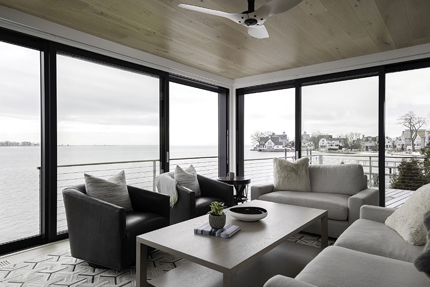
Photo courtesy of Marvin
This Norwalk residence uses multi-slide doors and casement crank-out windows to optimize the view as if the home is floating on Long Island Sound.
BIG GLASS ON THE RISE
The world of glass—and big glass, in particular—is expanding. The term "big glass" is used to describe the increasingly popular trend for glass panels and assemblies that are larger than traditional windows and doors in residential design. These panels and assemblies allow more natural light to enter a space, offer opportunity for better ventilation, and provide more unobstructed views of the surrounding environment. Big glass can range from assemblies of smaller windows that provide a big-glass effect to large-panel windows and doors that appear to take up entire walls.
Big glass is popular in architectural design because it creates transparency and openness, blurs the lines between indoor and outdoor spaces, and contributes to the health, safety, and well-being of occupants. But its popularity has soared even higher in recent years. In the past, more glass meant high energy bills, drafty interiors, outside noise, and aesthetic limitations.
Modern glazing systems are stronger, more energy-efficient, and offer better insulation than previous versions. With the use of advanced coatings, glazing, and insulation, architects can design buildings that are not only visually stunning but also environmentally friendly and more durable. In the long run, durability can translate into cost savings.
Big glass is popular because of the trend toward a more contemporary and modern aesthetic in home design which lends itself to clean lines and larger windows and doors. It is also popular because of the growing trend of sustainability and energy efficiency in architecture. Larger-scale window and door assemblies can help reduce energy consumption by allowing more natural light to enter, reducing the need for artificial light. By leveraging quality window and door solutions with the appropriate U-Factor, Solar Heat Gain Coefficient, and Visible Light Transmittance rating, a building's overall energy consumption can be reduced, which is increasingly important as society becomes more focused on reducing our carbon footprint.
These days, new innovations, technologies, and standards lead to big-glass products and designs that lead to window and door solutions that open up design options. Residential architects, builders, and developers can now incorporate natural light, views, and air that meet their aesthetic vision. And, just as importantly, it allows them to find solutions for homeowners living in a post-pandemic world in which health, safety, well-being, and sustainability are of the utmost importance.
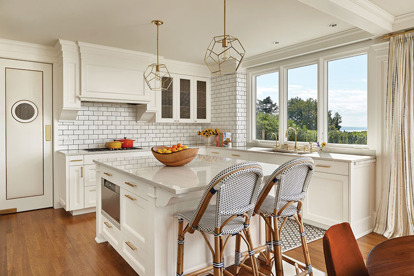
Photo courtesy of Marvin
A Seattle-based 1910s-era colonial revival renovation features high-performance double-hung windows with a contemporary classic look that maximizes views but doesn’t clash with the original style.
Case Study: Minimalist-Inspired Home
On Long Island Sound, a new residential property demonstrates the innovative ways glass can transform the traditional notion of a beach house. The project evolved out of circumstance and necessity. Owners Kerry and Jed Stevens bought a small cottage in Norwalk, Connecticut with a prime view of the water and a more traditional, quaint, beachside aesthetic. It seemed like a dream.
But there was a problem: The cottage was located in the flood zone and did not comply with code. Initially, the Stevens, along with their architecture firm, planned to do a renovation that involved lifting the house out of the floodplain, getting it compliant with FEMA regulations, and making improvements from top to bottom. After further inspection, the firm found more items on the interior that weren’t compliant, so the decision was made to raze the old house and build a new one.
Taking advantage of the opportunity, the Stevens agreed on a whole new design–a total departure from the traditional charm of a seaside cottage. They decided to go big with a design that utilizes the latest technology in glass. The newly constructed home is no longer at the mercy of the floodplain. It is a much edgier version of seaside living–a home that juts over the water and captures ocean views from a multitude of vantage points with a design featuring clean lines, narrow profiles, and large expanses of glass. Kerry likens the modern, minimalist design to creating the sensation of being in a boat on the water.
The project used casement windows with sashes hinged on one side, which crank outward. Multi-slide doors also provide that open, big-glass feel. Both windows and doors are designed with energy-efficient double-pane glass featuring Low-E2 coating and argon-gas fill. This type of glass, along with overhangs and internal shades, helped optimize the home to effectively manage solar heat gain. In the summer, it rejects the sun’s heat and damaging UV rays. In the winter, it reflects heat back into the room, offering comfortable temperatures in all types of weather.
The multi-slide doors, located in the master bedroom and living room, allow fresh air to filter through the house in the warmer months. The combination of ventilation and visual seamlessness between indoor and outdoor spaces provides the sensation of being outdoors–even when you are inside.
This project’s windows and doors are made from a durable high-density fiberglass exterior and a frame design that offers high-end thermal performance in even demanding climates. The casement windows have a design pressure (DP) rating of 50 and the multi-slide doors have a performance grade rating of PG45 (DP and PG will be discussed in more detail later in this CEU). In addition, the architects were able to specify rated and certified performance door sills that could be dropped down into the door frame and still stand up against harsh northeast weather – a test they have already endured.
The Norwalk project looks modern for many reasons. It uses concrete, steel, and raw wood, and clean lines. Big glass is used in this case as a way to both elevate the aesthetic and tie it all together while still maintaining functionality and durability required in such an often unpredictable environment.
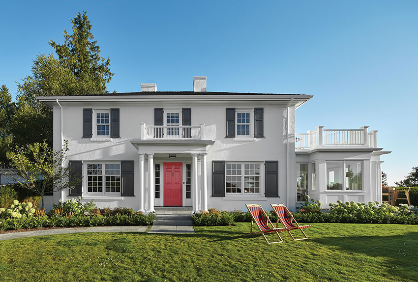
Photo courtesy of Marvin
The owners of this Seattle-based renovation project chose high-performance windows that would maximize views but still maintain the home’s original colonial revival style.
Responding to Human Needs
The pandemic and associated work restrictions created a dramatic surge of interest in home designs—for both new and renovation projects. For many people, the newfound reality of spending much more time at home instead of at work or out in public places motivated many to make changes in the places where they live. Some of those changes were based on the need to have adults working from home, school children learning from home, or a mix of people simply performing more of their daily activities from home than was previously typical.
A renewed interest in home design and renovations designs and renovations happened relatively quickly once pandemic shutdowns began in the U.S. In a survey conducted by Houzz in June 2020, 71% of homeowners reported that they were thinking about or actively working on home improvement projects, with 60% of respondents citing the pandemic as their reason. Additionally, 47% of respondents said they were upgrading home offices or workspaces, and 42% were improving outdoor living spaces.
Google Trends also showed early data indicating that browser searches for home office ideas increased by 110% between March and May 2020. And, in a survey conducted by the American Institute of Architects in August 2020, 68% of architects reported that they had seen an increase in demand for home offices, and 58% had seen an increase in demand for exercise rooms.
Innovations in home design inspired by pandemic life have not decreased, even as many people have returned to offices. The America at Home study—a nationally representative survey of U.S. adults ages 25-74 with household incomes of $50,000+ per year—shows an increase among Americans since the pandemic in the perception that a home needs to be designed to support health and well-being. The desire to customize homes in more innovative ways—and with that central goal in mind—has led to an increase in new products and technologies. And those technologies—along with performance standards and code requirements—help architects realize architectural visions in which they can provide clients better access to natural light, air, and views.
In the case of big-glass designs, design flexibility stems from the variety of high-performance window and door types that are available to architects. And, while large-scale windows and large-size doors can maximize access to light, air, and views in spectacular ways, they need not be restricted to homes with million-dollar views. Designing around any view (small container garden), incorporating well-placed windows and doors, and bringing in fresh air benefit homes of all sizes and locations.
Case Study: Queen Anne Update
A young couple purchased a 1910s-era colonial revival in Seattle’s Queen Anne neighborhood. They loved the home’s classic look and wanted to update it without compromising its character, charm, and period detail. To meet these goals, they worked with an architecture firm to come up with a plan that consisted of expanding and remodeling the kitchen and adding a new main bedroom with an ensuite bath. The crown jewel of the project, though, entailed building a sunroom on the west side of the home, providing unobstructed views of Puget Sound and the Olympic Mountains.
Glazing was central to the project. Naturally, new windows would be installed in the sunroom addition and bedroom, but the old double-hung windows throughout the main house would also need to be replaced. And while it was highly important to the owners that their new windows provide security and energy efficiency, they still wanted to maintain the home’s original colonial revival style. With this idea in mind, the architects laid out a plan for windows that would blend seamlessly into the architecture, as if they had always been there.
The owners chose a high-performance double-hung window with a contemporary classic look–one that maximizes views but doesn’t clash with the colonial revival style. The windows offered energy efficiency, an auto-lock feature for security, and durable hardware. In the end, they were able to choose from a multitude of traditional sticking options and profiles to meet their design goals and performance expectations.
The renovation was not without a few surprises. When the old windows were removed, they discovered that the home had been built with interlocking, structural clay tile that was covered in stucco. Before being replaced by concrete masonry units, structural clay tile was commonly used throughout North America in the late 19th and early 20th centuries, although it’s uncommon to find Seattle-area homes built in this way.
The unique building material did, however, provide an unexpected benefit; the extra thickness of the masonry wall allowed for greater setback with the new windows, which provided more coverage and protection from Seattle’s challenging temperate marine climate. Because the windows are not flush with the exterior wall, the masonry acts as an umbrella, shielding the windows from precipitation. To account for the recess, the project’s architect worked with finishing carpenters to trim out the windows, giving them a seamless appearance with the exterior wall.
And then there was the sunroom. To optimize views and comfort, the designers chose a mix of large direct glaze and operable casement windows for cross ventilation. Despite their lack of traditional embellishments, the windows in the sunroom work beautifully within the context of the rest of the home, while at the same time giving the space its own unique identity within it.
For this project energy efficiency was not just a personal choice for the owners. Washington state energy code requires meeting .30 U Value, which is higher than some other states. The array of big glass design options—and flexible customization—supported the project goals well, and helped introduce more light, air, and views, while keeping the historic aesthetic intact.
THE SCENIC EVOLUTION: BIG-GLASS TECHNOLOGIES AND TRENDS
Window and door designs have evolved significantly over the years, with manufacturers introducing a range of new materials, technologies, and styles in order to enhance their functionality, security, and aesthetics. Each type of door and window has its own origin story, but one of the best examples of how big-glass products have evolved is in the case of patio doors.
Patio doors were traditionally made of wood or aluminum, and they were designed for the simple purpose of providing quick and easy access to outdoor spaces. In the 1950s and 1960s, sliding patio doors became more widely available and affordable, and they quickly became a popular feature in modernist architecture and suburban homes. By the 1970s, sliding patio doors were incorporated into residential construction across North America.
These early sliding patio doors had large glass panels that allowed natural light into the home, as well as easy access to air and views. But these earlier doors were not very energy-efficient and could be prone to leaks and drafts, which made them less popular in colder climates. The door operation was not always reliable in terms of durability and function. They were limited to a basic look that could only go so far in contributing to aesthetic design. Security was also a concern, and patio doors in this era had basic locking mechanisms that were relatively easy to bypass.
Technology and design innovations have significantly changed the status of patio doors—and all windows and doors—opening the proverbial door to big-glass possibilities. New materials such as vinyl, fiberglass, and composites have helped make doors and windows more durable, energy efficient, and lower maintenance. They incorporate energy-efficient features such as low-e glass, argon gas fills, and insulated frames to improve insulation and reduce energy costs. These modern doors and windows are designed with robust locking mechanisms, tempered glass, and impact-resistant materials to improve security and protect against break-ins. They are available in a variety of styles, finishes, and sizes to suit different architectural designs and preferences.
New technology has also advanced windows and doors with automated opening and closing systems, smart locks, and built-in blinds–all of which provide more convenience and advance their functionality. All these technologies have advanced occupant health, safety, and well-being, by making possible products that enhance views, natural light, and natural ventilation, as well as support thermal comfort and emotional security.
Architects looking to incorporate big-glass designs into a project can consider several window and door products and design configurations. Sliding doors, including patio doors, lift and slide doors, multi-slide doors, and bifold doors, are common for exterior glass design and can be utilized for big-glass looks that offer more opportunities for natural light, natural air, and views. Swinging doors, including pivot doors, are also options for big-glass looks since they can be specified with large glass panels in heights and lengths that exceed standard door sizes.
Double-hung windows, casement windows, awning windows, and sliding windows are popular choices for architects who are considering big-glass designs that enhance natural light, natural ventilation, and views.
When deciding on the specific configuration for a door or window system, designers should take into consideration size and weight, available space for the system, and the specific design goals of the project. They also need to consider several performance attributes, including energy efficiency, acoustic performance, security, durability, aesthetics, and sustainability.
OTHER CONSIDERATIONS FOR BIG-GLASS DESIGN
Sills
Sills are a key performance consideration for water management. Swinging doors require different types of sills than sliding doors but the details and configuration of each need to work with the door panel to achieve the needed level of protection. In cases where lower levels of water and weather protection are needed, then a flush sill is possible. In cases where higher levels of protection are needed (i.e., the door is fully exposed on the exterior) then the manufacturer's choices should be reviewed for both leakage resistance and proper drainage. It is worth noting that in some cases, the sills for sliding doors actually have greater performance results than sills or thresholds for swinging doors.
For operable windows, a sill should be designed to manage water that may collect on the surface of the sill or flow into the window opening. The sill should be sloped away from the window to allow water to drain properly and prevent water from infiltrating the homes. Other considerations include condensation management, material selection based on the climate, aesthetics, and accessibility. The sill height should comply with accessibility guidelines to ensure the window is usable by all occupants.
Home Automation
Home automation is becoming increasingly popular and combines well with big-glass design.
The ability for homeowners to control aspects of their home such as lighting, temperature, and security systems, all from a single device, such as a smartphone or tablet, is appealing to busy people as well as those who require assistance. Home automation helps save energy costs because the systems can be automated or controlled from afar, tailored only to when occupants need to use the energy. It also adds a level of security that gives homeowners peace of mind–emotional comfort–by making it easier to lock window and door systems.
There are always new innovations for home automation, but here are a few that architects can consider when designing big-glass projects.
Lock Status Sensor and Remote Operation
Some operable windows and doors can be upgraded with sensors that are installed in the factory and fully concealed in the product. They can be wired or wirelessly connected, sending a signal to the homeowner’s integrated smart home security system to indicate if windows and doors are closed and locked or unlocked. These types of lock status sensors are an open system, so they are compatible with other smart home systems, which also allows for flexibility if a homeowner needs to change their security system in the future. Operable windows and doors can sometimes be specified with remote control devices. These devices can be a good choice for large doors and when occupants require assistance.
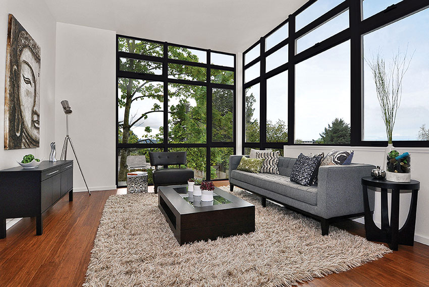
Photo courtesy of Marvin
A wall can serve as a canvas for architects to create their vision for more natural light, natural ventilation, and breathtaking views, but this type of design can be a complex process that presents both engineering and design challenges.
Big-Glass Window Design
Window technology has increased durability and energy efficiency and given architects more design freedom. The expansion of window options also allows architects the opportunity to directly combine these high-performance windows into aesthetically striking window assemblies that–in some cases–nearly open entire walls to glass. With window mulling, a wall can serve as a canvas on which architects feature a variety of conjoined window shapes and sizes to support their vision for more natural light, natural ventilation, and breathtaking views. Mulled window assemblies are two or more separate windows that have been joined together to fit into a single opening in a wall. When specified and installed correctly, mulled windows improve the potential and practicality for achieving a higher glass-to-wall ratio, compared to installing a series of individually framed windows or a single, large window.
owever, as building professionals know, the process is not as simple as joining several high-performance windowpanes together. Despite the technological advances in windows, window mulling can be a complex process that presents both an engineering and design challenge. The more glazing a design combines, the more the assembly must be interrogated to uphold its durability and energy efficiency qualities. Window mulling requires careful consideration of multiple factors, and architects need to have a thorough understanding of the options available and the impact of each option on the performance and aesthetics of the building.
There are different types of window-mulling configurations, including horizontal, vertical, and unitized, and each configuration has its own set of advantages and disadvantages. The choice of configuration will depend on factors such as the building's design, the location of the windows, and the desired aesthetic.
Window mulling can impact the performance of the windows in terms of energy efficiency, sound transmission, and water penetration resistance. Architects need to consider factors such as the size and spacing of the windows, the type of glazing, and the quality of the sealant to ensure that the mullions do not compromise the performance of the windows.
Window mulling also requires coordination between multiple trades, including the window manufacturer, the installer, and the general contractor. Architects need to ensure that all parties involved in the window installation process understand the specifications for the mulling configuration to ensure a successful installation.
“There have been situations where our products have been put in applications without an understanding of the product limitations and environmental stresses,” says Jeff Siverhus, a senior product manager with Marvin. “The contractor could be installing a PG 40-rated window assembly when a PG rating of 50 or 60 is required.” Inadequate reinforcement could lead to leaking or even catastrophic window wall failure.
Many of the challenges surrounding mulled windows are addressed in the factory. There, the individual units are fastened together securely into finished assemblies for more modest big windows, or into two or more subassemblies that are designed to be joined together in the field for larger installations. The maximum size of a subassembly is determined in part by shipping restrictions that make it difficult to transport a unit larger than 8-feet-by-8-feet.
Building codes also are critical in the big window wall world, as the beefy headers needed to distribute the load over an enhanced window opening places hard limits on how big your window wall can be. In recent years the challenge of mulling windows, even in residences, has become even more complicated by the fact that window assemblies are growing larger and larger. This makes it more difficult to address key engineering questions about assembly and performance.
Factory vs. Field
Architects should understand how and why to consider and specify for factory versus field mulled window assemblies. Factory mulled windows are often considered ideal because the factory approach usually ensures that each window unit is joined together with precision, resulting in consistent sizing, alignment, and performance. This is especially important when creating larger window units, where any inconsistencies could result in air leaks, water infiltration, or other issues. There is also generally greater quality control since the manufacturer can check that each window unit meets its specifications before it is shipped. Choosing factory mulling can also provide greater warranty protection since the manufacturer is responsible for the entire window unit, including the mullion joint. And that warranty can provide peace of mind for both the homeowner and the contractor. In addition, factory mulling can save time and labor costs since the window units are already pre-assembled and ready to install.
Field mulling often faces challenges with weather conditions, materials, and lack of assembly stations. That being said, field mulling can be a viable option in certain situations such as when working with unique or custom window configurations that are harder to achieve through factory mulling. It may also be preferred and necessary with some big-glass designs in situations where projects must ship in sub-assemblies and transportation or accessibility to the job site is a concern. Some companies now offer options for quick on-site assembly by delivering large factory-mulled sub-assemblies, with all necessary components and instructions included, so that contractors have a much easier, faster assembly prep kit that results in an AAMA-450-certified window assembly. This type of assembly solution can help speed construction timelines by incorporating all of the necessary fasteners, clips, caps, and other parts—which reduces specifying time and the risk of missing parts and lost time at the jobsite.
AAMA 450
American Architectural Manufacturers Association (AAMA) 450 is the certification standard for the testing and rating of windows, doors, and skylights. It is useful to both engineers and manufacturers and makes compliance of mulled systems easier and more effective. Specifically, it is a performance standard for the thermal transmittance (U-factor) of fenestration products— how well a window, door, or skylight prevents heat from escaping a building. The lower the U-factor, the better the insulation value of the fenestration product. AAMA 450 sets performance requirements for U-factors for various types of fenestration products under different test conditions.
Mulled assemblies that are not built or tested to meet this standard may not meet performance expectations. Especially in extreme weather conditions and in particular locales, such as coastal regions, underperformance can be a hazard to the safety of building occupants.
Originally published in 2000 as AAMA 450-00, Voluntary Performance Rating Method for Mulled Fenestration Assemblies, the document defined procedures for arriving at a meaningful design pressure (DP) rating from which air, water, and structural performance of mulled assemblies could be more effectively assessed. The standard has been updated since, including in response to major events like the 2004 and 2005 hurricane seasons, when the U.S. experienced a series of severe storms. Hurricanes Charley, Frances, Ivan, and Jeanne caused a combined $62.2 billion in damage and resulted in 123 deaths in 2004. In 2005, a total of 28 named storms hit the U.S., including most notably Hurricane Katrina, which devastated the city of New Orleans, caused more than $125 billion in damage, and resulted in over 1,800 deaths.
AAMA 450 offers three options for determining the overall DP rating of a mulled fenestration system, which is the lower design pressure achieved by either an individual product or by the mulled system, as determined by testing, calculation, or a combination of the two.
The first option tests the total system configuration, which must meet the minimum performance levels for air leakage, water resistance, and uniform load as outlined in the North American Fenestration Standard (NAFS). The second option tests the mullion elements of individual components using a simple beam concentrated load test with the load applied at the center span. Deflection under the load and permanent deflection after the load removal are recorded and must be less than L/175. The third option allows for structural calculations which must follow the procedures stated in Engineering Design Rules set forth by the Fenestration and Glazing Industry Alliance (FGIA)/AAMA 2502-19. Those calculations include:
- Area moment of inertia, bending moments, and section modulus of the mullion element
- Deflection of the mullion element (not to exceed L/175 for spans of 13 feet, 6 inches or less and L/240 + ¼-inch for spans more than 13 feet, 6 inches at the given design pressure)
- Extreme fiber stress (structurally calculated)
AAMA 450-20 Update
In January 2021, FGIA announced an update to the mulled assemblies document. AAMA 450-20, renamed the standard as “Performance Rating Method for Mulled Combination Assemblies, Composite Units, and Other Mulled Fenestration Systems.” It describes test procedures and calculation procedures for determining the performance of mulled fenestration systems for both factory-assembled or field assembly with parts and instructions supplied by the fenestration product manufacturer. Changes and additions have been made to deflection limits, connection strength, load application, and the anchorage of mullion elements.
One particularly notable change is with composite units, which have been brought fully into the scope of the standard, together with storefront and curtainwall fenestration products and side-hinged doors. (A composite unit indicates two or more independent fenestration units, each of which must meet appropriate NAFS requirements, utilizing integral mullions within a single continuous outer main frame.)
With so many different available configurations of mulled fenestration systems, analysis and testing can be overwhelming. For that reason, a key component of AAMA 450 is the allowance of “product grouping” for the purpose of qualifying multiple designs with a single test or evaluation. While other published methods, such as AAMA 2502-19, Comparative Analysis Procedure for Window and Door Products, allow rating of untested sizes, AAMA 450-20 allows rating of untested configurations. The product group can include several different types of operating windows of different performance classes that are combined in a variety of ways using the same mullion profile. One test may qualify all possible combinations of the window types based on the weakest configuration.
Wind-load Calculations for Mulled Assemblies
We all understand that windows are one of the most vulnerable parts of a building when it comes to wind damage. When wind strikes a building, it creates a pressure differential on the building envelope that can cause windows to break or even be blown out of their frames, posing a safety hazard and potential for significant damage to the building and its contents.
Mulled window assemblies are particularly susceptible to wind damage because they create larger surface areas for the wind to act upon. The wind load on a mulled window assembly is greater than that on a single window unit, and the assembly may also have weaker points at the mullions where the units are joined together.
Understanding wind load for mulled window assemblies allows architects and engineers to design window systems that can withstand the forces of wind and protect the building and its occupants. By calculating the wind load on the windows and specifying windows that meet the necessary wind-load rating, architects can ensure that the windows are strong enough to resist the forces of wind and prevent damage or injury. Additionally, proper installation techniques and detailing, such as using appropriate framing and mullion design, can further increase the strength of the window system and reduce the risk of wind damage.
Mulled window assemblies may require additional structure in situations where the expected wind loads exceed the capacity of the window system to withstand them. This can occur in areas that are prone to high winds or in buildings with large window openings that are exposed to wind. One situation where additional structure may be required is when the wind loads exceed the design pressure rating of the windows. In this case, the window system may need to be reinforced with additional framing, such as steel or wood bracing, to increase its strength and rigidity.
How might an architect detect that a mulled window assembly needs additional structure? As a general rule, if the assembly creates a 3-way or 4-way intersection and it exceeds 6 feet in any one direction, additional structure is necessary. Other considerations for determining if additional structure is required would be looking at project site location in terms of terrain and region type. For instance, if the project is in a coastal region or Tornado Alley, it is clearly more susceptible to wind-load issues. And it is also more susceptible if it is on a hill or bluff, in an open field, or next to any body of water, not just oceanside.
Architects must also consider the type of building. High-rise buildings and commercial buildings with large storefronts or curtain walls tend to require additional structure. But as big-glass designs for residential homes become more prevalent, architects will need to be ever more aware of additional durability considerations for window assemblies.
Once it is determined that additional structure is necessary, architects should consult with structural engineers or other licensed design professionals to perform a wind-load calculation and analysis. Structural engineers use specialized software and engineering principles to calculate the expected wind loads on a building based on factors such as the building's location, height, and design. Architects will need to supply the project site address, building elevation drawings, and window assembly size.
The Project Site Address
The project site address will determine the location wind speeds, which will be entered into the calculator. Location wind speeds are based on the specific geographic location of the building or structure. This information is typically obtained from the ASCE 7 standard, which provides detailed information on the wind speed maps for the U.S. and other countries.
The ASCE 7 standard provides wind speed maps that divide the U.S. into zones based on the likelihood of encountering high winds. These maps are based on historical weather data and other factors, such as topography and surrounding terrain, that can affect wind patterns.
To determine the location wind speed for a particular building or structure, the design professional first determines the zone in which the building is located and then consults the wind speed maps or other sources that provide information on local wind conditions.
The project site address will also determine the building’s exposure category. The exposure category is based on the building's location and is used to determine the level of wind exposure that the building will experience.
Exposure categories are:
Category B
- Typical urban or suburban area
- Building and trees the same height or taller
Category C
- Open areas
- Buildings taller than their surroundings
Category D
Waterfront with 1-mile exposure
Building Elevation Drawings
Building elevation drawings are needed to determine the overall height of the building and the zone location of the assembly itself.
All of this information will be used to determine design pressure (DP)—the maximum pressure that a building or structure is designed to withstand from external loads, such as wind or seismic forces (see the DP sidebar for a more in-depth discussion).
Window Assembly Size
Finally, architects need to submit window assembly size, including individual window size. The size and shape of the window units are important factors in wind-load calculations. The larger the window, the greater the wind load it will experience. The shape of the window can also affect the wind load, as curved or irregular shapes can create turbulence and increase wind pressure.
The total wind load on the mulled windows is calculated by adding up the wind pressure on each individual window unit and multiplying it by the area of each unit.
Once the wind load is calculated, architects can use this information to make adjustments to the design of the mulled window units so that they are strong enough to withstand the forces of wind. This may involve considering windows with more appropriate wind-load ratings, making sure they have the proper framing and mullion design, and ensuring that the installation meets local building codes and standards.

Photo courtesy of Marvin
By selecting energy-efficient windows that reduce both heat loss and solar heat gain, architects can help reduce energy costs for occupants and improve the comfort of indoor spaces.
GLAZING COATINGS TO IMPROVE ENERGY PERFORMANCE
According to a recent National Association of Homebuilders study, of all the efficient features one could have, 83 percent of homeowners found it essential or highly desirable to have energy-efficient windows, making it number one on the list of priorities.
When selecting window assemblies for big-glass designs, there are multiple factors to consider. For instance, while increasing the amount of glazing can increase heating and cooling demand, the daylighting achieved through more glazing can significantly reduce electric lighting demand. Reducing the amount of heat transfer between the interior and exterior of a building is one way to reduce heating and cooling costs and improve occupant comfort. The ability to control solar heat gain is also important. While some solar heat gain may be desirable in colder climates, where it can help reduce heating costs, excessive solar heat gain can be a problem in warmer climates, where it can increase cooling costs and make indoor spaces uncomfortable. High-performance glass can also be used to help boost energy efficiency and control solar heat gain.
Energy-efficient windows are typically designed to reduce both heat loss and solar heat gain, and may include features such as low-emissivity coatings, reflective coatings, and insulating gas fills between panes of glass. By selecting windows that address both issues, architects can help reduce energy costs for occupants and improve the comfort of indoor spaces.
Low-emissivity (low-E) coatings are designed to reduce the amount of heat that escapes through the glass in cold weather. Emissivity is a measure of how well the surface of an object absorbs and re-radiates (or gives off) thermal energy. Very reflective surfaces have a low emissivity, and duller objects that absorb heat have a high emissivity. Emissivity is measured on a scale ranging 0.0 to 1.0, with 0.0 being a perfect reflector and 1.0 being a perfect emitter, aka a “blackbody.” (A blackbody is a theoretical object in physics that does not really exist, but is a useful concept when talking about emissivity.)
Low-E coatings work by reflecting heat back into the room, rather than allowing it to escape through the glass. In addition to reducing heat loss in winter, low-E coatings can also help control solar heat gain in the summer by reflecting some of the sun's heat back outside. The microscopically thin, transparent metal or metallic oxide layers deposited on a glass surface can be selected from a variety of options with different levels of heat gain control to match different climate needs.
Here are a few low-E coatings architects can consider:
Low E1: Low E1 coating is a good choice for maximum solar heat gain (or maximum heat transferring into the house from the sun) and radiant heating properties (keeping heat on the side of the glass where it originated). This type of coating is generally used in Northern climates where heating is prioritized over cooling. This type of coating reaps maximum benefits when windows are positioned to receive direct sun exposure.
Low E2: Low E2 is the most common low-E coating since it works well across most geographic regions and climates. Low E2 with two metallic coatings balances less solar heat gain and improved radiant heating properties.
Low E3: Low E3 is used in applications where solar heat gain may be a concern. The coating uses multiple metallic layers for radiant properties similar to Low E2. It is most commonly used in Southern, sunny climates where cooling is prioritized over heating.
Low ERS: Low ERS is a higher-performing low-E glass with significantly improved U Factors. This coating is placed on the interior surface of the glass and can be touched. It is used in conjunction with Low E2 or Low E3 and helps reflect radiant heat back into the room. This means it will have a slightly cooler interior glass surface since the heat is not absorbed by the glass. The cooler surface may see a bit more condensation in cold climates versus traditional low-E glass make-ups.
Keeping building orientation, climate, and daylighting goals in mind, design professionals can choose architectural glass that will help their specific project obtain the most daylighting benefits while controlling glare and solar heat gain. The key terms to remember when specifying these systems include U-factor, solar heat gain coefficient (SHGC), and visual transmittance (VT).
U-factor: A measure of the heat flow through the window due to convection, conduction, and radiation. The higher the U-factor, the more heat is transferred or lost through the window. Low U-factors can help reduce heating and cooling loads. The typical range to look for is between 0.20-1.20.
Solar heat gain coefficient (SHGC): The ratio of the solar heat gain entering the space through the glazing to the incident solar radiation. SHGC is measured on a scale between 0 and 1; the lower the SHGC, the less heat is transmitted. Choose low SHGC when cooling loads are high and a higher SHGC for passive solar heating.
Visible light transmittance (VT): The percentage of visible light entering the space through the glazing system. VT is measured on a scale of 0 to 1; the higher the VT, the more light that is transmitted. Clear glazing has a VT of about 0.90. A high VT is desirable for effective daylighting.
Tints and low-emissivity, or low-e, coatings can impact both VT and U-factors. Typically applied to the glass during manufacture, these coatings limit the transmission of infrared and near-infrared wavelengths and so reduce the emittance of radiant heat.
Standards
Glass doors and windows can generally be evaluated by most of the same third-party independent testing standards. These include comprehensive testing by the National Fenestration Rating Council (NFRC) which identifies the total energy performance of tested units for heat transfer (U-factor), solar heat gain, visible light transmission, air infiltration, and condensation resistance. It also includes the Fenestration and Glazing Industry Alliance (FGIA), which is a recent collaboration of the American Architectural Manufacturers Association (AAMA) and the Insulating Glass Manufacturers Alliance (IGMA). The FGIA now provides standard testing and standards for all types of windows and doors. Finally, there is also ASTM International, which has developed numerous tests for different types of glass, glazing systems, and window and door products. All of these are relevant performance standards for exterior glass doors of all types, just as they are to windows and similar fenestration.
HEALTHFUL HOMES BY DESIGN
"For years, we’ve been following emerging ways of living in the home and uncovered a clear desire for more access to natural light, air, and views. The pandemic heightened homeowner awareness of these desires and fast-tracked renovations and remodeling to realize these benefits. Today we’re seeing homeowners strive to strike a balance between flexible multi-purpose spaces and dedicated areas for respite while integrating the outdoors and leveraging their home in pursuit of better living."
-Christine Marvin, CMXO Marvin Windows and Doors
In a 2013 University of Colorado study published in The Journal of Sleep, participants spent a week camping in the Rocky Mountains without access to artificial light. During the first two days of the camping trip, they were not allowed to use flashlights or electronic devices, and they were exposed only to natural light during the day and darkness at night. For the next five days, the participants were allowed to use flashlights and electronic devices, but they were still exposed only to natural light during the day and darkness at night.
The results of the study showed that exposure to natural light during the day helped to regulate the participants' circadian rhythms. The researchers found that the participants' melatonin levels, which are a marker of the body's circadian rhythm, were synchronized with the natural light-dark cycle. And that synchronization is what helps promote healthy sleep patterns and wakefulness during the day.
The study also found that exposure to natural light during the day led to an increase in physical activity and a decrease in the amount of time spent in sedentary activities. This study, among others, has helped architects and designers understand the importance of and consider approaches to designing homes and buildings that allow for natural light to enter the indoor environment.
With an emphasis on large expanses of glass, big-glass designs can have a significant impact on the health and well-being of building occupants. In a University of Illinois study, natural light improved the mood and physical activity of office workers—evidence that can easily translate to remote workers or occupants with in-home offices. Studies with school children and with elderly people in nursing homes have also shown the benefits of natural light, in both cognitive performance, mood, and over health.
Big-glass designs also provide a connection to the outdoors, which can reduce stress levels and increase feelings of well-being. Views of nature have been shown to have a positive effect on mental health. In addition, large operable glass windows and doors provide a literal connection to the outdoors—encouraging homeowners to step outside and utilize outdoor areas for serene relaxation, entertaining guests, and other activities.
Natural ventilation from operable windows can have several positive effects on occupant health and well-being. It can help improve indoor air quality by bringing in fresh air from the outdoors and flushing out stale indoor air. This can reduce levels of indoor air pollutants, such as volatile organic compounds (VOCs) and carbon dioxide, which can cause respiratory problems and other health issues. It can help regulate indoor temperature and humidity levels, creating a more comfortable indoor environment, and ultimately leading to a reduction in the need for mechanical cooling and heating, which can save energy and reduce costs.
The regulation of indoor temperature and air quality leads to another benefit: It can promote better sleep quality. Studies have shown that, just like with natural light, exposure to fresh air and lower indoor temperatures can lead to deeper, more restful sleep. During the day, natural airflow can promote relaxation and reduce feelings of anxiety and stress, which tends to have a ripple effect of benefits for occupants.
As mentioned earlier, high-performance big-glass designs can improve thermal comfort by allowing for natural daylighting and solar heat gain, which can help reduce the need for artificial lighting and heating. Glazed facades can help reduce outdoor noise levels, providing a more peaceful indoor environment. Acoustic glazing can also be used to further reduce noise levels and create a more comfortable indoor environment. Architects should consider these factors when designing with large glass panels and mulling designs to ensure they meet the needs of occupants. When designed well, a home with enhanced views, natural ventilation, and natural light can greatly impact the lives of its occupants for the better.
Big-glass design doesn’t just affect the well-being of occupants, it influences the outside environment. Designers can have a positive impact on the aesthetics of a home and the surrounding area. Homes with large glass facades can add visual interest to both urban and rural landscapes and can create a sense of openness and transparency. In addition, when natural light enters a building and the surrounding area, it can improve the mood and well-being of people who view the building, as well as the occupants.
Erika Fredrickson is a writer/editor focusing on technology, environment, and history. She frequently contributes to continuing education courses and publications through Confluence Communications.