Continuous Insulation Systems for Exterior Walls


Thermal Resistance with Spray Foam Insulation
There are two fundamental ways to use spray foam insulation in exterior wall assemblies—as a way to insulate in stud cavities and as a way to provide exterior continuous insulation.
Stud Cavity Insulation
The primary method of insulating a stud wall system whether framed in wood or metal has not changed notably over the past 40 years. The traditional approach has been for batt type insulation to be placed between the framing members. In this approach, the insulation is routinely compromised due to compression by mechanical, plumbing, or electrical components embedded within the same stud cavity. Also not to be overlooked is the sag potential of many batt insulation products which can result in loose fits that don't end up completely filling the stud cavities over time, resulting in less than stated thermal performance.
Spray foam insulation overcomes many of these thermal performance issues in stud cavities. Low-density open cell insulation is most commonly used for this application since its physical characteristics are well suited to form to the conditions of the cavities and the cost is economical. By field applying it against the interior face of exposed sheathing, it can fill the cavity space completely, thus assuring the full thermal value of the wall is realized. If all of the mechanical and electrical work is roughed into the wall, then the insulation can appropriately fill around all of those irregularities as well creating a thorough installation. The end result is an insulated wall with a much more effective full R-value from the spray foam than a potentially compromised R-value for batt type insulation.
It should be noted that while stud cavity insulation systems have the benefit of economizing on wall thickness, they do not provide continuous insulation across the wall due to the recurring thermal bridges associated with the studs. Energy codes and green building standards have recently recognized that exterior walls with insulation installed between studs, particularly steel studs, have real performance limitations due to these thermal bridges. Most take into account the overall calculated U-factor of the total assembly and do one of two things. Either they set the required R-values of a typical assembly higher to take into account the lower performance due to thermal bridging, or they require that a maximum U-factor of the total assembly be achieved.
ASHRAE 90.1 which is appended to many energy codes and standards includes some very clear correction factors for this calculation. For example, a metal stud wall using 6-inch nominal studs at 16-inch o.c. may include insulation that carries a manufacturer's rating of approximately R-3.5 per inch for a total of approximately R-21. However, the frequency of the metal studs including the head and track pieces create a typical stud wall area that is on the order of 20 percent stud and track faces and only 80 percent solid insulation. This ratio compromises the overall effective wall R-value by as much as 65 percent. Therefore AHSRAE 90.1 assigns a total working value for this typical assembly of only R-7.4 (U-factor of 0.135) which is little more than a third of the insulation R-value.
At this level it does not meet the minimum energy performance levels required to be code compliant in most of the U.S. Therefore, in order to properly address the thermal bridging at each of the studs which reduces overall wall performance, an additional approach is needed as discussed below.
Exterior Continuous Insulation
A second approach of insulating wall assemblies is to use a continuous insulation layer installed on the outside of the stud wall framing and sheathing. It is this continuous insulation layer that is recognized in the code and U-factor calculations that makes up for and stops the heat transfer occurring at each stud. By insulating over the outside of the stud wall, the temperature difference across the studs is less thus reducing the rate of heat transfer. Further, the additional insulation adds to the overall thermal performance of the wall assembly quite dramatically since every inch installed is fully effective without any inherent thermal bridging or other compromises.
 |
Using a combination of low-density open cell spray foam insulation between steel studs and a continuous layer of medium-density closed cell spray foam insulation outside of the sheathing creates an exterior wall with superior thermal performance. Image courtesy of ICYNENE, Inc. |
When considering the make-up of an exterior wall assembly then, one very effective approach is to use a combination system. First, low-density open cell spray foam insulation is used to fill completely the cavities between the studs. Then medium-density closed cell insulation is sprayed as a continuous layer over the exterior sheathing of the stud wall. As a practical matter, the insulation should not be applied in depths any greater than 2 inches at a time (i.e. 2-inch lifts) or per manufacturers' recommendations, in order to allow the insulation to set up, cool and dry properly. The final insulation thickness can vary from 2 inches up to about 5 inches depending on the desired thermal performance of the wall recognizing that the closed cell insulation has a substantially higher R-value per inch than the open cell. It should be noted that the continuous insulation thickness and details will also need to meet the requirements of NFPA 285 and (ASTM E119 if a fire rated wall is required) in order to be code compliant as well.
The final continuous insulation layer thus creates a more fully insulated wall assembly with superior thermal performance that may also allow a smaller stud size to be used. For example, a nominal 4 inch stud that is filled with low-density spray foam insulation of R-3.5 per inch will yield a full depth R-value of about R-13. Adding the layer of medium-density spray foam insulation on the outside at R-6.9 per inch means that even at 2 inches, a continuous insulation layer of almost R-14 is achieved. All together, the combined wall assembly now delivers a total R-value of about R-27 in the same total wall thickness as a 6 inch stud wall that only delivered the approximately R-21 we saw in our previous example. More significantly, though, the thermal bridging effect is dramatically reduced by the continuous insulation layer, so the actual wall performance is far superior and much closer to the total cumulative values than it would be without it. This superior performance is rewarded in energy codes by recognizing the higher overall U-factor of the wall assembly that will come about as a result of the continuous insulation. When installed properly it also directly improves the overall energy performance and contributes to the corresponding energy cost savings of the building as well.
Once applied, the exterior layer of spray foam insulation obviously is not left exposed, but instead a masonry veneer or other exterior wall façade treatment is installed. If attachment anchors are required, then they will need to be installed to the sheathing layer before the closed cell spray foam insulation is applied. From a final design standpoint, the continuous layer of spray foam insulation can be treated like any other insulation in the wall assembly meaning that the final wall appearance and design does not need to be limited by its use. Rather, the enhanced performance and potentially easier installation make it more freeing to work with virtually any compatible façade type (providing it is a NFPA 285 compliant design for the spray foam insulation chosen).
 |
A continuous layer of medium-density closed cell spray foam insulation used in a traditional masonry wall provides durability and energy sealing performance. Image courtesy of ICYNENE, Inc. |
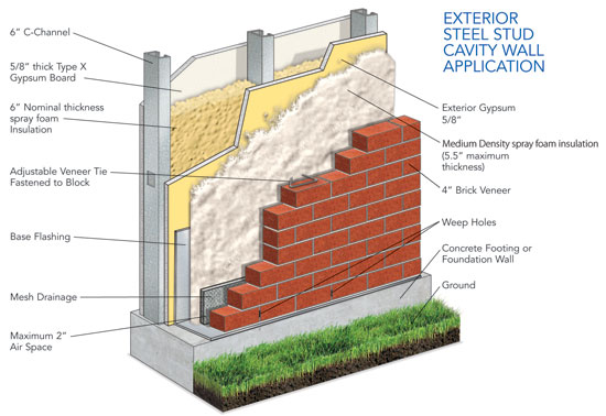
In the case of masonry walls that use CMU interior walls and exterior brick façade veneers, spray foam insulation is again a very logical choice. By spraying the continuous layer of medium-density closed cell foam over the outside face of the CMU, a high performance, tightly fitting, and durable insulation layer is created. In addition, the interior CMU wall now gets counted under energy codes and ASHRAE 90.1 as a “mass wall” inside the building envelope. A mass wall of this type helps to regulate temperature swings within an occupied space making the space, and the occupants, more comfortable and less prone to use more energy for heating or cooling.
When insulating masonry walls with spray foam insulation, the traditional method of erecting the CMU wall, applying masonry ties, installing insulation, and then laying up the masonry veneer can still be pursued in the conventional manner. Only, instead of relying on the mason to install the insulation and coordinate the masonry ties around it, now the mason can focus on masonry and an insulation installer can focus on spray foam insulation being applied properly. Once the CMU wall is prepared and ready, then medium-density closed cell insulation can be applied, again in 2 inch lifts, up to the thickness called for in the wall design. The masonry ties or anchors can be insulated tightly around them for best performance. Any openings or penetrations in the CMU can also be appropriately filled and sealed with the spray foam insulation. After the insulation is set and dry then it can be covered with the finish layer of masonry veneer. This rather conventional masonry wall approach has typically relied on a space or cavity being present between the insulation and the masonry veneer for moisture control and water drainage to occur and this should still be maintained when using spray foam insulation too. Since the material is capable of shedding water, this is a logical and very compatible use of this type of durable insulation.
Notice