This CE Center article is no longer eligible for receiving credits.
The movement to improve energy performance in buildings and lower their environmental impact is dramatically affecting the way new and renovation projects must be designed and built. This is particularly true with recently enacted energy code requirements for continuous insulation and continuous air barrier integration. Architects and building engineers looking for ways to meet or exceed these code requirements are more carefully looking at exterior wall assembly details. Finding ways to achieve the needed performance, maintain a budget, and still address aesthetics are all part of creating a successful design. Toward that end, Exterior Insulation and Finish Systems (EIFS) have been gaining favor as a tested and proven solution to this challenge. The system has always been based on a continuous insulation layer located on the outside of the exterior wall assembly. Compared to many traditional exterior cladding alternatives, it has historically proven to be very cost competitive. Due to manufacturing advances, performance and aesthetics aren't mutually exclusive since the latest offerings include a wide variety of finishes, textures, and colors providing the aesthetic appearance of brick, granite, stone, metal, and stucco.
The 2012 Codes: Raising the Bar on Performance
The family of International Codes promulgated by the International Codes Council (ICC) has either been adopted directly or used as the basis for building codes in most states and jurisdictions around the country. Throughout this article we will refer to provisions of the 2012 ICC codes but as with all code-related matters the local governing jurisdiction should be consulted for any details of applicability or clarification of locally adopted versions. We will also be discussing only commercial buildings defined as anything that is not a single-family or two-family residential building.
When it comes to the make-up of exterior walls in commercial buildings, the International Building Code (IBC) dedicates an entire chapter to this subject. Specifically Chapter 14 is appropriately titled “Exterior Walls” and provides a considerable level of both prescriptive and performance requirements. Like all code provisions, it does not offer design solutions, rather it indicates functions that must be met in the construction of an exterior commercial wall in rather specific terms.
 |
Exterior Insulation and Finish Systems (EIFS) provide continuous insulation to meet the latest code requirements in a wide variety of architectural finish options.
Photo courtesy of Dryvit Systems, Inc. |
In discussing the various components of exterior walls, there are several common terms used that are also defined by the code. An “exterior wall” is defined as a load bearing or non-load bearing wall used as an enclosing wall for a building. An “exterior wall assembly” or “wall envelope” is the total collection of components that are assembled to produce the final wall construction including framing, sheathing, and finish materials. An “exterior wall covering” is one or more finish materials applied to the outermost surfaces of an exterior wall assembly of which it is a part. A “veneer,” including masonry, wood, or others, is a facing type of exterior wall covering that does not add any strength to the wall assembly.
IBC Section 1403.2 – Weather Protection
Starting with the basics, the IBC states that “Exterior walls shall provide the building with a weather-resistant exterior wall envelope.” The intent is to protect the wall assembly materials and the building interior from the detrimental effects of the exterior environment. In particular it goes on to require four specific measures to achieve this intent:
Flashing. First is the use of flashing (discussed in detail in 1405.4) that is installed to prevent moisture from entering the wall assembly or to redirect it to the exterior where that happens. The code is rather specific about listing multiple places where flashing is required including door and window perimeters, wall penetrations/rough openings, terminations, and intersections with other elements and projections.
Water-resistive barrier. Second, the IBC requires the prevention of water accumulation in the wall assembly by requiring a water-resistive barrier behind the exterior wall covering. This barrier layer is described in more detail in Section 1404.2 but essentially calls for a minimum one layer of an approved material such as No. 15 asphalt felt complying with ASTM D 226 for Type 1 felt or other approved materials. This barrier can be attached to the exterior side of studs or sheathing but if conventional stucco is used, then the code requires two layers of water barrier. (This barrier will need to be fire tested as part of the testing discussed further for the overall wall as well.)
Drainage. Third, it goes on to require that a means of drainage be provided for any incidental water that does enter behind the exterior wall covering. This can take on the form of properly flashed weepholes detailed into masonry veneer construction or similar appropriate detailing at the bottom of rain screen assemblies where other finish surface options are used.
Condensation prevention. Fourth is protection against condensation forming in the wall assembly (addressed in 1405.3 and the International Energy Conservation Code, IECC). There are somewhat different provisions for different climate zones in the U.S., but code compliance is essentially achieved by providing a Class I or II vapor retarder in the exterior wall. Class I is described as sheet polyethylene film or non-perforated aluminum (foil) creating a very high level of protection. Class II is described as kraft paper faced batt insulation providing a lesser but acceptable level of condensation protection. Not allowed in this case is a Class III vapor retarder which is defined as latex or enamel paint.
International Energy Conservation Code (IECC) – 2012
One of the benefits of the full family of International Codes developed by the International Code Council is that they have been developed together so they are compatible and complementary with each other. This is the case with the IECC which builds upon the basic building code provisions in the IBC and adds compatible requirements for energy efficiency in buildings. As a comprehensive energy conservation code, it establishes minimum regulations for energy-efficient buildings using prescriptive and performance-related provisions. While the IECC addresses both residential and commercial buildings, Chapter 4 focuses specifically on commercial buildings.
With respect to energy-efficient design, the first fundamental decision that needs to be made is which energy code will be used in the design of a commercial building. The IECC recognizes that there are highly developed national standards in place with the similar intent for energy efficiency and therefore has adopted them by reference. The most significant one is the ASHRAE Standard 90.1, the latest edition of which is 2010. Since this standard addresses all of the same items and issues as the IECC, code compliance can be demonstrated using either the criteria listed solely in the IECC or using the criteria in ASHRAE 90.1. There are some differences between the two in that one may be more stringent or lenient than the other on certain specific items. However the end result for determining overall energy efficiency is regarded as equivalent.
There is a catch here, however. The entire design team must agree on which basis is being used to demonstrate compliance with the code on all aspects. Either all of the IECC provisions or all of the 90.1 provisions must be selected—they cannot be co-mingled. The choice will affect all aspects of energy efficiency including the entire building envelope, fenestration, mechanical systems, lighting design, and electrical loads. Since we are limiting our discussion to exterior walls here, the distinction is slight, since items addressed in both the code and 90.1 are the same, although requirements vary slightly. Familiarity with the actual language in the selected compliance path will obviously be important for specific building projects with specific design teams.
In regards to exterior walls, there are essentially two significant requirements that have been updated in the IECC and addressed in 90.1. These two items are added in addition to the four listed in the IBC.
Continuous insulation. The energy code and adopted standards have always established minimum insulation and thermal performance levels for exterior walls. The latest versions recognize the limitations of construction and in many cases require not only common wall cavities in stud wall construction to be insulated, but for continuous layers of uninterrupted insulation to be provided as well. The reason behind the requirement comes from extensive study and analysis by ASHRAE and others on the notable inefficiencies of traditional cavity wall insulation, particularly using metal studs. The issue is the numerous interruptions of the insulation by the framing members or studs that act as direct “thermal bridges” between the inside and outside. Many architects and engineers understand that the insulation is compromised in this situation and therefore decide to simply increase the amount of insulation to raise the R-value between the studs. While this sounds logical, ASHRAE studies have shown it doesn't work. The reality is that using a minimal R-11 cavity insulation between steel studs has been tested to show that the effective R-value of the wall to be about R-5.5 or 50 percent less than the stated insulation R-value. Increasing the insulation to R-19 doesn't perform much better since its effective R-value tested out at just over R-7 or 63 percent less than its stated value. Even bumping the insulation up to R-25 only creates a modest effective R-value of R-7.75 or 69 percent less than the stated value.
 |
Effective R-values of cavity wall insulation with metal studs compared to the stated R-value of the insulation.
Image courtesy of Dryvit Systems, Inc. |
Recognizing this significant practical problem, the IECC and ASHRAE 90.1 allow for two means to demonstrate thermal performance. The first is with prescriptive R-values for walls based on the building's location in one of eight climate zones throughout the U.S. Those prescriptive requirements now include many instances where a minimum amount of continuous insulation (ci) must be used in addition to insulation provided between the studs. The ci reduces the thermal bridging effect of those studs and allows the true effective R-value of the wall to be higher than without it. The R-values listed in the code apply only to the insulation itself and assume cavity stud wall construction to allow for an adequate overall energy performance of the wall.
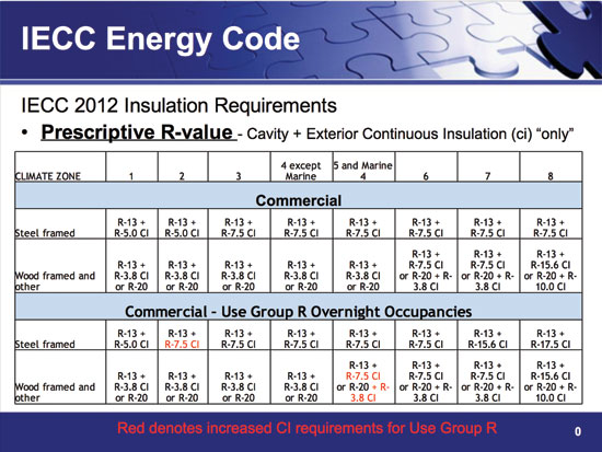 |
The International Energy Conservation Code and ASHRAE 90.1 now include prescriptive requirements for R-values of both cavity wall insulation and continuous insulation.
Image courtesy of Dryvit Systems, Inc. |
The second way to demonstrate thermal performance is to show a calculated U-factor for the total wall assembly, not just the insulation. ASHRAE 90.1 includes Appendix A which lists various common wall assemblies and their tested U-factors. If the wall assembly being used in a particular project is not listed, then it will need to be custom calculated. While that is relatively easy for wood frame construction, it is more complicated for metal stud construction or other alternatives. Hence, it is likely that some sophisticated software will be needed such as THERM which is publicly available from Lawrence Berkeley National Laboratory (LBNL). Either way, code compliance is demonstrated by comparing the maximum allowable U-factor in the code or 90.1 to the identified U-factor for the wall in the subject building. In many cases, the U-factor analysis will likely be more stringent than basing compliance on the R-value tables in the code. However, for walls that are completely insulated with ci, the difference will likely be less significant since the full R-value of the ci is realized in the assembly and not compromised by thermal bridging.
 |
 |
Thermal imaging shows the notable difference in heat loss between an exterior wall that relies on stud walls with cavity insulation (top) and a wall that uses continuous insulation (bottom).
Photos courtesy of Dryvit Systems, Inc. and The Dow Chemical Company |
Air leakage/continuous air barrier requirements. Both the 2012 IECC and ASHRAE 90.1-2010 recognize the significant impact that unwanted air infiltration has on a building's energy performance. It has been well proven that air leaks and drafts that occur around wall openings, penetrations, joints, transitions, and other common building elements add up quickly to become the equivalent of leaving a window or door open in a conditioned space. The code and 90.1 each address this issue and mandate that certain things be done; however they vary in their approach. ASHRAE 90.1 requires the general sealing of joints, seams, and material transitions throughout the building. It identifies exterior sheathing with sealed joints as an approved air barrier “material” in this case. The IECC includes the same air sealing requirements but goes beyond to specifically require a continuous air barrier be included in the exterior wall system in all but the three warmest climate zones. To demonstrate compliance, this air barrier must be tested based on any one of three options:
A. The material itself can be tested to meet an air permeability rating (≤ 0.004 cfm/ft² @ 75 Pa pressure per ASTM E 2178).
B. A full wall assembly can be tested to show an average air leakage (≤ 0.04 cfm/ft² per ASTM E 2357, 1677 or 283).
C. The entire building can be tested after it is constructed and show an average air leakage (≤ 0.40 cfm/ft² per ASTM E 779).
Regardless of the compliance path selected, the intent is the same—reduce air infiltration in buildings to an acceptable level. Further, the means to do so must be designed to withstand positive and negative pressures and stack effect pressures.
| Metro Career Academy |
|
Project: Metro Career Academy, Oklahoma City, Oklahoma
Architect: Quinn & Associates, Oklahoma City, Oklahoma
General Contractor: CMS Willowbrook, Oklahoma City, Oklahoma
EIFS Applicator: DMG Masonry, Arlington, Texas
EIFS Type & Finish: Engineered drainage system with specialty brick and limestone finish
It is not an overstatement to say that clay brick masonry is the foundation of modern Oklahoma City. The look of brick and stone masonry continues to be very popular with area architects and building owners everywhere. However, the ever-increasing demands of climbing construction costs, energy efficiency, and life-cycle performance led architect Fred Quinn of Quinn & Associates to research different materials to meet the demands of this high-performance facility.
The original design of the Metro Career Academy (MCA) building called for 24,000 square feet of clay brick and 13,000 square feet of cast stone. When Quinn learned that he could use an EIFS with the same look and save nearly 50 percent in construction costs (materials and installation) versus the clay brick and stone, it was an easy decision.
In addition to this dramatic reduction in cladding costs, making the decision to switch to EIFS during the schematic design phase allowed the owners of the Metro Career Academy to harvest the full range of benefits from the lightweight cladding, including less structural support required, a reduced construction schedule, LEED points, projected energy savings, and fewer delivery trucks, i.e. reduced environmental impact. By substituting the 1.5 pound per square foot adhesively attached moisture drainage EIFS for the labor-intensive 40+ pounds per square foot masonry and stone, the designer was able to subtract more than 96 percent of the anticipated weight of the building’s skin. Eliminating 1,424,500 pounds from the exterior walls of the building produced additional savings in the concrete and steel support system required to carry that initially designed load. Cris Callins, manager of preconstruction with CMS Willowbrook, estimated that the reduced demand for structural support and the more rapid installation of the EIFS allowed her project manager to cut a full 15 weeks from the MCA building’s construction schedule, lowering manpower, equipment, and insurance costs as well as easily meeting the owner’s demanding completion date.
The MCA project utilized 4 inches of exterior continuous insulation (ci) as part of the EIFS, which helped the MCA to achieve its goal of LEED Gold certification for this project. The project earned the full 10 points in the Energy & Atmosphere Credit 1 category available under LEED v2.2. The computer modeled performance anticipates an energy usage savings of 34.8 percent and an energy cost reduction of 42.8 percent annually compared to the baseline. Without taking into consideration rising costs of energy or inflation, it is possible to conservatively estimate the value of these energy savings over a 50-year life cycle of the MCA facility at more than $1.7 million.
Overall, the EIFS assembly allowed the entire project team to increase the insulation value of the wall, enhance the moisture protection of the building envelope, and lower the cost of the exterior cladding, while retaining the desired look of masonry and stone. The engineered, fully tested system includes:
- Fluid-applied AWRB
- Fluid-applied flexible flashings at all transitions and wall penetration rough openings
- Drainage plane with weep details
- Exterior ci
- Continuous air barrier
- High-impact reinforced assembly
- Flexible aesthetic finish coat conveying original brick and stone appearance
|
IBC Chapter 26 – Foam Plastic Insulation
Certain types of foam plastic insulation have become popular in recent times because they not only provide thermal insulation, they can also provide water resistance, continuous air barrier qualities, and condensation prevention in some cases. Recognizing the growing use of foam plastic insulation in exterior wall assemblies, the code identifies three specific safety criteria that must be met. Primarily and justifiably so, the intent is to protect the building and people in the event of a fire where combustible plastic materials are present. Therefore all three of these conditions must be met when using them; however it is the third one that is usually the most significant:
A. Surface-burning characteristics are the first set of criteria including a maximum flame spread index and a maximum smoke developed index based on the standard ASTM E 84 test procedure. (Section 2603.3/2603.5.4)
B. Second, a 15-minute interior thermal barrier is required in order to separate the interior from the foam plastic in the event that a fire does occur. (Section 2603.4/2603.5.2). The stated acceptable thermal barrier in this case is ½-inch gypsum board or a demonstrated equivalent that will provide the needed separation.
C. Third and most important the testing of the complete exterior wall assembly is required whenever foam plastic insulation is used. (Section 2603.5.5). Under this part of the code, the specific exterior wall assembly being used must be tested in accordance with and comply with the acceptance criteria of NFPA 285. That means that any given foam plastic product needs to be tested multiple times since it is the total wall assembly, not just the foam plastic that is being tested. This requirement holds regardless of the wall classification type for commercial buildings (type I, II, III, or IV).
Note that in demonstrating compliance with these three mandatory criteria, the code does not distinguish between different types of foam plastic insulation such as polystyrene, polyisocyanurate, or urethane foam. Even though there may be differences in their make-up and manufacture, the code requires that they all must meet these three basic criteria and any other incidental criteria depending on their use.
 |
Properly designed EIFS meet all of the building code requirements for using foam plastic insulation in exterior walls.
|
Conventional Exterior Walls: Performance Issues
Meeting each of the various code and performance requirements for exterior walls has commonly meant addressing them each individually. Therefore, the very common framed cavity walls using metal studs in commercial buildings (either as direct structural support or as infill between structural steel or concrete) are typically detailed and constructed with different layers of materials. While this is logical and would seem to allow for a reasonable degree of quality control, the reality is that this process has some inherent material limitations and compatibilities that can cause compromises on the actual performance, and code compliance, of the wall.
First, as we have already seen, the use of metal studs provides a dramatic reduction in the effectiveness of non-ci when it is interrupted by studs. But thermal bridging occurs at other locations as well. This is particularly evident on multi-story buildings where a stud wall assembly is used on multiple floors. The studs commonly rest on and get anchored to a floor structure that for example could be 4 to 6 inches of concrete in a metal deck or a 10-inch to 12-inch wood framed structure. In this type of construction, the insulation in the wall studs stops above and below the floor structure meaning the floor edge is exposed along the full length and width of the building. It is therefore a very significant thermal bridge since there is nothing to prevent heat from being transferred between the inside and the outside of the building along the entire perimeter of the floor construction.
Significant thermal bridging can also occur around structural elements such as columns or beams made of steel or concrete if they are not insulated on the outside. Stud framing is often set between these structural elements to create a smooth interior wall surface. However, that means that the insulation stops where the studs stop, essentially leaving a gaping interruption of the insulation. Hence the code requires ci be provided to address this problem and defines it as insulation that is continuous across all structural members without thermal bridges other than fasteners and service openings. It is installed on the interior, exterior or is integral to any opaque surface of the building envelope.
 |
Exterior continuous insulation effectively stops thermal bridging found in conventional metal stud wall.
Images courtesy of Dryvit Systems, Inc. |
The most popular place to add this ci is on the outside face of the exterior wall sheathing. All by itself, this is the best way to improve energy performance which is clearly the desirable outcome. But the practicality of doing so presents itself as an issue when detailing the entire wall assembly from the interior face to the exterior face including the cladding that will go over the ci. Continuous insulation mounted on the exterior moves traditional claddings further out from the wall meaning that it is essentially cantilevered further off the structural line. This increases moment stresses at points of anchoring and bearing and needs to be addressed, usually by increasing the size of lintels, attachment members and foundations thus adding to the cost. It also makes the total wall assembly thicker which will impact the detailing of window and door openings including the sizing of frames for all of them. In the end, it will be required to address all of these items, but the reality is that it is extra work both in design and construction to be sure that all systems are working together properly and staying within budget and schedule.
Conventional construction limitations apply to the development of a continuous air barrier too. Vapor and air barriers that are installed in sheets or rolls certainly work well at their center but they will have seams along their edges. Further they need to be integrated into the transition areas where walls join together, where they meet other surfaces such as floors and roofs, and where they meet openings such as doors and windows. All of these locations are potential breaches or interruptions in the barrier that need to be overcome or detailed away. In looking at how those details are handled, issues of NFPA 285 compliance may come into play to be sure that the total wall system will still pass the fire testing requirements of the code. In particular, commercial building walls above 40 feet in height are required by the IBC 2012 to have water-resistive barriers that are NFPA 285 compliant. This provision will also apply to the continuous air barrier where it is integrated into a combined air/ water-resistive barrier. If the wall construction does not match a previously tested was assembly, then a test will need to be performed for the particular assembly designed for the project which will of course add cost and time to the project.
Exterior Insulation and Finish System: Performance Solutions
In light of the challenges and limitations of using traditional construction to meet the requirements of the 2012 code including the 2010 ASHRAE 90.1, Exterior Insulation and Finish Systems (EIFS) are being looked at for a growing number of projects. These systems were first developed in Europe in the 1950s to address increasing energy cost and post war re-development. In 1969 they were introduced to the United States which means that the industry has 44 years of experience as the building system that can claim to be the “original continuous insulation.” During that time, they have been installed on over 1 million buildings in North America primarily by companies with manufacturing facilities in the U.S.
Since EIFS are engineered and designed as complete ci systems, they very effectively address all of the ci provisions of the code. The insulation in these systems is intended to be installed as a continuous layer over the outside of sheathing to provide both thermal insulation properties and to act as a substrate for the durability and aesthetic layers of the EIFS assembly. Hence, they provide a complete exterior surface that eliminates virtually all thermal bridging in most cases allowing the insulation to perform up to its full potential. That also means that metal studs can be sized only as needed to address structural design issues since their depth is no longer needed for perceived R-value increases through thicker cavity insulation. Although EIFS are more commonly installed on wall assemblies with cavity insulation, the ci value of EIFS can be selected so that they do not require any additional insulation to meet the performance goals. In that case, the stud cavity is available for running mechanical and electrical lines cleanly and efficiently without interference or interruption of the cavity insulation.
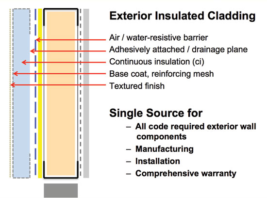 |
Typical components of an EIFS.
Image courtesy of Dryvit Systems, Inc. |
A typical EIFS is made up of several components installed from the face of the exterior wall sheathing on an exterior wall and progressing outward. Currently EIFS with integral moisture drainage are most widely specified for commercial construction. This type of system includes a proprietary fluid applied air/water resistive barrier (AWRB). It is installed directly over the face of the sheathing and includes a treatment of all sheathing board joints as well as all inside and outside corners. The AWRB is then properly integrated through the use of compatible fluid or membrane flashing materials into all transition, wall penetration, rough opening and contiguous wall infill areas all as a means of creating the needed continuous air barrier throughout the entire exterior wall envelope.
Next, adhesive applied in a specific vertical notched trowel pattern is used to both secure the ci layer to the AWRB and to create an integral draining plane. Once the insulation boards are set in place, their outside faces and return edges are encapsulated with a fiberglass mesh reinforced base coat. This mesh adds strength, durability and impact resistance to the outside primary weathering surface. When ready, the reinforced base coat is covered with a final textured aesthetic finish coat. Since all of these layers are installed by the same trade, there is a single source for all code required exterior wall components, for the manufactured products, for their installation, and for a comprehensive “system” warranty.
In looking at the wall system as a total assembly, it is important to first note that all EIFS have been tested for compliance with NFPA 285 for foam plastic insulation and air/water-resistive barriers and pass the fire safety requirements accordingly. Further, without the need for a separate veneer or cladding, EIFS become single source systems for all components of an exterior wall assembly other than the structure and the sheathing.
EIFS have a ripple effect on the rest of the building design as well since they are extremely lightweight weighing on average only 1.5 pounds per square foot. This has a notable impact on the total weight of the exterior wall which can ripple through to the structural system requiring lighter and smaller columns, beams, footings, etc. dramatically saving construction cost. In a similar manner, since an additional veneer layer isn't needed, that means that the wall system doesn't get unduly thick or complicated to detail. This keeps all exterior wall penetrations such as at doors, windows and louvers very conventional to detail and easier to build. All together, EIFS represent very positive attributes when evaluating exterior veneer or cladding options.
Specifying Design Options in EIFS
When specifying EIFS there are certain specification details to pay attention to so that the right products are specified appropriate to the location where they will be installed. The Master Format section number commonly used is in the 07 24 00 series for several types of Exterior Insulation and Finish Systems. These include separate specifications for Polymer-Based (PB) Barrier EIFS, Water-Drainage EIFS, and Direct Applied Finish Systems. Some of the relevant items to address in a standard 3-part specification format are highlighted below.
Part 1: General
• Quality Assurance – Since EIFS have been in use for over four decades, there are an abundance of tests and standards that have been applied to and developed for various types of EIFS. In fact some have noted that EIFS are the most thoroughly tested exterior cladding on the market. We have highlighted some of the major tests in this article already, but each project should be reviewed for additional applicable tests and standards as they may apply to a particular type of system or a particular location.
• Submittals – Some submittals can be requested during the design review stage of a project or they can be reviewed during construction. Common submittals might include product data, samples, and test reports on the total EIFS. In cases of panelized construction, it would be appropriate to request shop drawings for the panelized system. A mock-up of the system including typical detailing and sealant joint application may also be appropriate.
• Coordination – Since the EIFS will be applied to a substrate and integrated into wall components installed by others it is important that the substrate and contiguous wall components are specified, installed, and coordinated so that the entire wall assembly works together similar to specifying other veneers and claddings. It is strongly recommended that the General Contractor schedules an EIFS pre-installation/coordination conference on site including all subcontractors involved in exterior envelope materials that meet or terminate at the EIFS. This conference usually occurs about the time the exterior sheathing is completed in its entirety.
• Warranty – Competitive warranties should be carefully reviewed. It is reasonable to request a warranty based on a comprehensive single source for any material defects and labor to replace any such material defects along with aspects of fade performance and no depreciation for the term of the warranty. For EIFS with drainage it is also reasonable to specify that the warranty covers underlying damage to framing or sheathing for moisture intrusion as a result of any material defect.
Part 2: Products
• Products – Since EIFS are entirely code compliant and warranted, it will be important to specify that all materials, products, and accessories come from the same source. As with all systems, there are options and choices among manufactured products. Perhaps the most significant in regard to thermal performance will be the choice of insulation type since various open and closed cell foam insulation boards are available with differing thermal and permeability properties. Generally speaking, open cell insulation which is most widely specified is lighter, more permeable, and less costly, but has a slightly lower R-value per inch than closed cell insulation boards. There are also choices in regard to the type and strength of fiberglass reinforcing mesh that is used in the system. The appropriate mesh can be specified for the anticipated conditions ranging from a standard impact condition up to the ability to resist hurricane force high impact through multiple layers of reinforcing mesh and provide long term durability. Consult manufacturers to see the properties of the products that they provide.
 |
EIFS finish options can be specified in a wide range of choices including brick, stucco, granite, and even metal appearances.
|
• Finishes – This is an area that has evolved notably in recent years. Finish options now include a wide range of appearances and include the look of stucco, brick, limestone, granite, and even metal in virtually any color. Naturally there will be differences between manufacturers on this, so it will be important to consult manufacturers' literature early in the design process to determine the options available.
Part 3: Execution
• Examination and Preparation – All work provided by other trades including the substrates, flashings, general building waterproofing, roof/wall connections, etc. must be examined to be sure they are all in place and installed properly. This examination and coordination should all be part of the pre-installation conference noted above. Missing this step could cause unwanted water or weather to penetrate behind the EIFS and compromise the building. Once all work is found acceptable, then the substrate should be prepared to be flat and free from anything that could inhibit proper direct adhesion or application of the AWRB.
• Installation and Field Quality Control – Since EIFS are installed in the field—except for panelized assemblies, it is extremely important that qualified and trained installers perform the work. Including appropriate installer requirements in this part of the specification is very appropriate but should likely be done in consultation with manufacturers to understand the current training and any certification status within the industry. It should be noted that the IBC requires an inspection of the AWRB layer in an EIFS with Moisture Drainage system by either the design professional of record or a third party inspector firm. Consideration for independent third party inspection of the entire building envelope is also an excellent idea.
• Cleaning and Protection – Most EIFS clean easily following installation in accordance with manufacturer's instructions. The finished system should be protected from weather and any sources of damage until the system is dry and any remaining flashings, sealants, etc. are installed.
Conclusion
Meeting code requirements for ci, air leakage, continuous air barriers, and condensation protection through the use of Exterior Insulated Finish Systems provides many distinct advantages to traditional construction techniques. As presented, EIFS as ci systems eliminate thermal bridging and meet or exceed all current building, energy and fire performance code requirements. As coordinated systems they enhance envelope energy efficiency, reduce energy consumption, control air and moisture infiltration, and protect the exterior wall assembly from vapor condensation. All of these attributes support sustainable design and earning LEED credits in a green building. Perhaps equally important in many cases, EIFS provide freedom of architectural styles in that they support many alternative finish aesthetics. And compared to other options that require more weight, more labor, and more trades, EIFS can notably reduce construction cost.
These benefits of EIFS have been realized in hundreds of thousands of projects around the world using systems that provide a single-source, seamless and sustainable cladding solutions for buildings of any shape, size and type. Simply put, the latest EIFS provide everything needed from a building code and ci perspective. They can also now provide everything desired from a performance and aesthetic standpoint to create buildings that will perform and look good for years to come.
Peter J. Arsenault, FAIA, NCARB, LEED AP, is a nationally known architect, sustainability consultant, technical writer, and continuing education presenter. www.linkedin.com/in/pjaarch
 |
Outsulation® by Dryvit is a fully tested, code-compliant EIFS, providing an air/water-resistive barrier, exterior CI, and durable finishes to buildings worldwide. Outsulation offers lower construction costs, improved energy efficiency, and long-term
sustainability compared to other exterior walls. The final appearance can look like brick, stucco, metal, granite, and limestone. www.dryvit.com |