Combination Air and Water-Resistive Barriers in Exterior Walls


IBC Definitions
Recognizing that there has been some confusion on the role and function of air, water, and vapor barriers as related to wall construction, the committee of professionals involved in writing and updating the codes spend considerable time and effort on establishing appropriate definitions for code-mandated elements. Specifically, the latest (2012) version of the International Building Code includes in Chapter 2, Section 202 a number of relevant definitions as part of the list of standard definitions used in the code. These include specific definitions for exterior walls, vapor barriers (as contrasted with a vapor permeable membrane), and water-resistant barriers (WRBs). For the sake of consistency, we will use the same terms with the same meanings throughout this article. (See sidebar below.)
IBC Exterior Wall Requirements
Chapter 14 of the IBC describes the particulars for exterior walls including mandatory performance requirements (IBC 1403). In clear and certain terms, it states that “Exterior walls shall provide the building with a weather-resistant exterior wall envelope.” It goes on to require that “The exterior wall envelope shall include flashing … (and) shall be designed and constructed in such a manner as to prevent the accumulation of water within the wall assembly by providing a water-resistive barrier behind the exterior veneer … and a means for draining water that enters the assembly to the exterior.” Keeping in mind that this is all about the general integrity of the exterior wall, the clear intent is to avoid damage to the wall from water and weather by requiring the use of flashing, a water-resistive barrier, and drainage for any water that does penetrate. There are some exceptions listed for concrete or masonry walls or exterior insulation and finish systems (EIFS) provided other relevant portions of the IBC are followed. There is also an exception for showing compliance for drainage through testing as prescribed in the code (IBC 1403.2). Some details of these requirements are elaborated on as follows:
Image courtesy of International Code Council
Chapter 14 of the International Building Code requires that exterior walls be constructed for integrity and protection against water and vapor.
▶ Flashing. The mandatory and prescriptive details of flashing are specifically called out to “be installed in such a manner so as to prevent moisture from entering the wall or to redirect it to the exterior. Flashing shall be installed at the perimeters of exterior door and window assemblies, penetrations and terminations of exterior wall assemblies, exterior wall intersections with roofs, chimneys, porches, decks, balconies and similar projections, and at built-in gutters and similar locations where moisture could enter the wall.” (IBC 1405.4) Properly detailed and installed flashing is clearly a must.
▶ Fire testing of water-resistive barriers. The code recognizes that the use of a water-resistive barrier cannot compromise the fire and flame propagation requirements of the rest of the code. Hence it states: “Exterior walls on buildings of Type I, II, III or IV construction that are greater than 40 feet (12,192 mm) in height above grade plane and contain a combustible water-resistive barrier shall be tested in accordance with and comply with the acceptance criteria of NFPA 285.” (IBC 1403.5) The cited test is NFPA 285: Standard Fire Test Method for Evaluation of Fire Propagation Characteristics of Exterior Non-Load-Bearing Wall Assemblies Containing Combustible Components. This test applies to an entire wall assembly that contains any combustible products. The intent is to determine if the entire assembly, not just any particular product, can be declared safe under specific fire conditions. As such, compliance is determined not by testing an individual material but a full assembly.
▶ Vapor barriers. Looking at the total wall assembly, the code states “Protection against condensation in the exterior wall assembly shall be provided…” (IBC 1403.2) which recognizes the damage potential from vapor condensing in an exterior wall and deteriorating construction materials through rot, rust, or mold. Hence the code goes on to require, based on the IBC definitions, that “Class I or II vapor retarders shall be provided on the interior side of frame walls in Zones 5, 6, 7, 8 and Marine 4.” (IBC 1405.3) Zones are determined by looking in the International Energy Conservation Code (IECC) but the requirement for its inclusion remains in the IBC. The IBC does allow for some cases where Class III vapor retarders can be used depending on the wall construction details (IBC 1405.3.1).
International Energy Conservation Code—Raising the Bar
While the IBC establishes the basic requirements for exterior walls from a general building construction sense, the 2012 International Energy Conservation Code (IECC) goes further to address energy use in buildings. The beauty of the family of codes prepared by the International Code Council (ICC) is the coordination between them, meaning that these two codes have been painstakingly reviewed to complement and not contradict each other among concurrent versions. Hence the IECC uses similar format and language to the IBC but also acknowledges the need to coordinate requirements.
IECC Definitions
The IECC uses the same general building definitions as the IBC but goes on to add a few that are specific to energy conservation. Among them are air barriers, which are recognized as a significant deterrent to air infiltration flowing through exterior wall systems. Such air flow is understood to alter the indoor air makeup of a building such that it will cause heating and cooling systems within a conditioned space to work harder and use more energy. It can also contribute to people inside the building being less comfortable and adjusting the thermostat set points to compensate but using more energy in the process. Note that the IECC clarifies that both above-grade and below-grade walls are part of its definition of exterior walls.
IECC Air Barrier Requirements
There are specific, mandatory requirements for air barriers that are addressed for both residential and commercial buildings in the IECC. The commercial building requirements are actually less stringent and detailed than the requirements for residential buildings but far reaching and thorough nonetheless in terms of the thermal envelope—including exterior walls. Also, it should be noted that compliance with the IECC can be demonstrated either by following the provisions of the code directly or by showing compliance with ANSI/ ASHRAE / IESNA Standard 90.1. While the overall energy performance of buildings is generally the same between the different compliance methods, there are differences in details, including differences in detailed requirements for air barriers. For this discussion, we will be focused on the IECC compliance path.
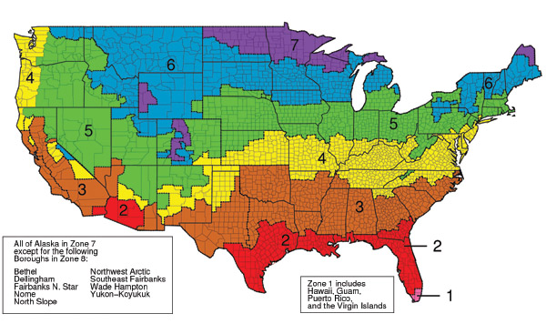
Image courtesy of International Code Council
The International Energy Conservation Code indicates climate zones and requires the use of air barriers as an energy conservation measure.
▶ Air barrier location. The IECC makes it very clear that “A continuous air barrier shall be provided throughout the building thermal envelope.” (IECC C402.4.1) That means all surfaces including walls. It goes on to say “The air barriers shall be permitted to be located on the inside or outside of the building envelope, located within the assemblies composing the envelope, or any combination thereof.” Typically, air barriers are placed on the outside of the wall assembly to prevent air infiltration from entering the assembly. Placing the air barrier on the outside of the walls also makes it much easier to maintain continuity across floors, ceilings, demising walls, etc.
▶ Air barrier continuity. The IECC imposes several mandatory requirements for the construction and use of an air barrier, including that it “shall be continuous for all assemblies that are the thermal envelope of the building and across the joints and assemblies.” (IECC C402.4.1.1) Further, recognizing the importance of joints and seams, the code requires “Air barrier joints and seams shall be sealed, including sealing transitions in places and changes in materials.” Similarly, at all penetrations, “the air barrier shall be caulked, gasketed, or otherwise sealed in a manner compatible with the construction materials and location.” (IECC C402.4.2) In all cases, joints, seams, seals, and penetrations “shall be securely installed in or on the joint for its entire length so as not to dislodge, loosen, or otherwise impair its ability to resist positive and negative pressure from wind, stack effect, and mechanical ventilation.” Achieving this performance requires attention to detail not just in design but in construction as well.
▶ Air permeability. The IECC relies on ASTM testing for the determination of a material or assembly to be considered an air barrier. Specifically ASTM E2178 Standard Test Method for Air Permeance of Building Materials establishes air permeability for a particular material to be no greater than 0.004 cfm/ft2 (0.02 L/s • m2) under a pressure differential of 0.3 inches water gauge (w.g.) (75 Pa). This threshold is based on historical requirements used in Canada and based on the amount of air that penetrates through a sheet of gypsum wallboard. Turning from a single material to an air barrier assembly, the threshold is not as strict but still a significant level to achieve. ASTM E2357 Standard Test Method for Determining Air Leakage of Air Barrier Assemblies and ASTM E1677 Standard Specification for Air Barrier (AB) Material or System for Low-Rise Framed Building Walls are cited by the IECC for assembly compliance. In these cases, an average air leakage not to exceed 0.04 cfm/ft2 (0.2 L/s • m2) under a pressure differential of 0.3 inches of water gauge (w.g.) (75 Pa) is required. Going from 4 thousandths to 4 hundredths of a cubic foot per minute might seem to be a big difference but the net number is still very small. Its significance lies in the fact that all of the joints, seams, connections, etc. need to be included in the test to be sure that the total assembly does indeed perform as a complete, un-breached air barrier.
Notice