Flights of Fancy in Long-Span Design


Terminal 4 at Barajas Airport, Madrid
Like waves in the ocean, the undulating roof form atop the new Terminal 4 at Madrid's Barajas Airport (see page 150) seems capable of going on for as long as the eye can see. And perhaps one day it will. Dating back to 1933, the Barajas Airport has been expanded several times, and the likelihood is great that future expansions will be necessary. The most recent addition for the Spanish National Airports Authority (AENA) was undertaken collaboratively by two architectural practices-Richard Rogers Partnership of London and Studio Lamela of Madrid-and two engineering firms-TPS in Croydon, U.K., and INITEC in Madrid. The design's straightforward linear organization and flexible kit of parts, expressed so clearly by its eye-catching roof, offers AENA the possibility of relatively quickly and easily adding on in most any direction in the years to come.
|
|||||||||||||
The new terminal is broken into four discrete horizontal bars that run parallel to each other: The first is an open canopy over the roadway; the next two form the main building for ticketing, security, baggage claim, and boarding areas for both national and Schengen flights (the latter are between countries in the Economic European Community that do not require passport control); and the fourth, and longest, is the satellite building that serves primarily international travel but can accommodate a mix of flight types if required. An underground train links the satellite to the main building. The same curvilinear roof module ripples across all four bars.
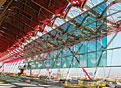
In cross section, the bars that form the enclosed buildings are constructed in three layers: a three-story concrete basement, a three-story concrete frame above grade, and the steel-framed roof. Longitudinally, each bar consists of a basic bay, about 30 feet wide, which is repeated as often as needed to create the necessary length. Expansion joints were inserted every eight bays to accommodate the wide swings in temperature expected at the roof plane.
The seagull-wing roof profile emerged early in the design. Recalls Carlos Lamela, executive president of Studio Lamela, "We were convinced from the beginning that we had to create a large container that would allow as much flexibility as possible, and we felt that we needed to cover the building with a very light structure that could provide the impression of grace and elegance." The roof's structural design was the responsibility of the architects, with technical assistance provided by TPS's subconsultants SKM Anthony Hunts of London.
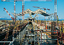
Fabricated from steel plates, the primary roof girders consist of three separate elements-a central "double-S bend" and two tapered outer sections. Once bolted together, a single girder measures 236 feet in length and ranges in depth from 59 inches at the center to 30 inches at each tip. The girders run parallel to each, approximately 30 feet on center.
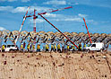
A pair of girders is supported at the center of their spans by four tapered steel branches bolted to a concrete column and by one Y-shaped element on either end. The roof structure was erected in segments. On the ground, the contractor assembled two double-S bend sections with the requisite perpendicular secondary members and two circular skylight frames to create the central module. This was then lifted onto and connected to the four branches of the center column. Subsequently, two tapered outer sections and their secondary members were assembled to form an end module. This too was lifted into place above the Y-shaped column and bolted to the central module. The process was repeated for the other end module, at which point the structure for a full module-with two full-length girders-was in place.
Notice


