From Mortar Snots to Perpends: The Basics of Through-Wall Flashing


Photo courtesy of Hyload Inc.
Components of through-wall flashing.
Through-Wall Flashing Components
Two contractors are engaged in the construction of a masonry wall, the mason and the sealant contractor. The components of through-wall flashing may include the following:
- One quarter inch or 5/16 inch steel relief angles.
- Flashing which is either brought through to form the drip edge or held back one-half inch from the face of the building.
- Metal drip installed to bring flashing through the wall and accept sealant
- Sealant
- Bonding Tape of backer-rods that allow the sealant to be adhered on two sides.
- Compressible filler that keeps moisture absorptive brick from growing into metal angles and causing a brick face to shear off.
In the field, the contractors work within the narrow confines of a wall cavity that can range from 3/8 – 1/2 inches. This skilled labor requires both knowledge and precision and any shortcuts can lead to building failures that can appear both immediately or after many years.
Membranes should be selected that are compatible with silicones and urethane sealants. They should also be stable when exposed to ultra-violet rays. Many synthetic materials will crack, discolor, harden or deteriorate when exposed to sunlight or harden as they age. High alkaline environments that are typical of masonry environments should not affect flashing materials and the manufacturer should supply verification of the materials chemical stability. Flashing can be specified to match mortar colors to reduce the visual impact of drip edges on a wall. Established manufacturers will provide design assistance, technical data, flashing details, installation instructions, and job site assistance to architects, engineers, specifiers and contractors.
Corners and Odd Shapes
Corners and odd shaped openings that are not properly flashed may be the first place that shows moisture damage. Mortar joints that crumble, efflorescence, cracked brick are the evidence that there is a problem. Special prefabricated shapes are available that can be used either in new construction or when repairing wall failures. These shapes can be specified for a variety of conditions. These include outside and inside 90 and 135 degree corners, level changes with built in end dams, window corners, internal and external corner caps, nut covers and many more. Depending on the manufacturer, the supply of prefabricated shapes can provide many benefits to speed project delivery.
Weep Holes
Solid cavity walls require weep holes that allow moisture to drain. The least expensive form of weep holes is the open head joint. They should be spaced every 24” or a minimum of two weeps above any opening. Some masons also use cotton cords as weeps. The BIA recommends that these should be placed a minimum of every 16” on center. Plastic tubes are not recommended because mortar droppings can dam up the openings in the tubes and they make perfect homes for insect nests.
Economics
Review the square foot costs of flashing before selecting a flashing material. The cost depends on the design of the building. The number of inside and outside corners, windows, doors, balconies and grade conditions will determine the number of special forms that will be required.
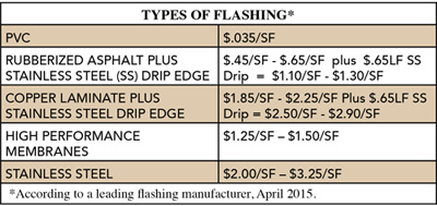
High performance membrane flashing systems with preformed shapes are comparable in price to both 5 oz. copper or rubberized asphalt flashing with a metal stainless steel drip edge. Any additional cost to use this product is equalized by advantages that include labor savings and durability. Keeping mortar snots from causing damage to an entire wall system is a matter of providing the correct “cold medicine.” Design professionals need to develop and participate in collaborative and integrated design and construction teams that include site problem solving throughout the length of the project. In addition to specifications, isometric drawings and site models provide better communication methods of difficult flashing details. The prescription for a successful project includes several preventative measures as well as the specification of a high performance through-wall flashing membrane systems.
Endnotes
- Cavity Walls. http://www.maconline.org/tech/design/cavity2web.pdf. 3/18/2015.
- Building Science Digests. http://www.buildingscience.com/documents/digests/bsd-108-investigating-and-diagnosing-moisture-problems 3/18/2015.
- Nicastro, P.E. “Magazine Masonry cavity walls; flashing not extended to face of wall” Construction Specifier, March 1996.
- Drip Edge/Flashing Extension. http://www.parkerblock.com/pdf/divisions/brick/contractors/tech-note-21b-brick-masonry-cavity-walls-detailing.pdf March 20, 2015.
- http://www.gobrick.com/Resources/About-BIA-Regions/Mission-Services. March 22, 2015.
Architect Celeste Allen Novak, FAIA, LEED AP, specializes in sustainable design and planning in Ann Arbor, Michigan. She is the author of “Designing Rainwater Harvesting Systems: Integrating Rainwater Into Building Systems.” www.celesteallennovakarchitect.com
| Hyload is part of IKO, a family business operating for more than 60 years providing global manufacturing and supply of quality roofing products. Hyload products include commercial roofing, waterproofing, and masonry through-wall flashing products. www.Hyload.com www.Hyload.com |
Notice