From Mortar Snots to Perpends: The Basics of Through-Wall Flashing


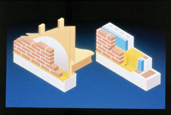
Photo courtesy of Hyload Inc.
This illustration shows two types of cavity walls, one with a block back-up wall and one with a wood back-up wall. The through-wall flashing is highlighted in yellow.
Cavity Walls and Through-Wall Flashing
There are two common types of masonry cavity wall construction. A cavity wall is constructed of two “wythes” of masonry separated by an opening of varying dimension. The term wythe is from old English as are many of the words used to describe masonry systems. Although masonry walls were used by the ancient Chinese, Greeks, and Romans, according to the Masonry Advisory Council, “Sometime in the early part of the 19th century, the cavity wall was probably reinvented by the British. Plans dating as early as 1805 suggest a type of construction, featuring two leaves of brickwork, bonded by headers spanning across a 6-inch cavity.”1 Early British publications suggest that cavity wall construction was a means to protect buildings from moisture penetration.

Photo by Gregory A. Jones, AIA, Hopkins Burns Design Studio
Lack of flashing and weeps has allowed water to collect on the top of the lintel, causing rust. Rust jacking has lifted the masonry above by approximately 3/8 inch, and deflected the lintel downward in the center where there is nothing to resist the rust’s expansive forces.
There are two types of cavity walls, the first using brick with a masonry block back up. The second type of cavity wall system uses metal ties to hold the walls together. Sometime in the mid-1800s, wrought iron ties were introduced in Southern England as part of a composite wall system. Cavity wall design came to the U.S. from Europe in the 1920s. Before that, barrier walls or composite walls with numerous layers of brick were used to construct most masonry buildings. In the 20th century, the second type of wall construction typically included an exterior brick wall connected by metal ties to a metal or wood stud wall.
Conceptually, moisture control in masonry walls is passive aggressive. Moisture that penetrates masonry veneer is allowed through the wall to run down its back face, dropping to the flashing and out through the weep system. Building paper, vapor barrier membranes or fluids are brought down the face of the back-up wall in a shingle fashion to shed any water to a waterproof flashing membrane. Wood studs are usually used in residential construction and steel studs for commercial work. “Through-wall” waterproof flashing membrane closes the gap between the two segments of the wall. The flashing provides a path for moisture to drain along the face of the back-up wall to the exterior of the building.

Photo courtesy of Hyload Inc.
“Through-wall” waterproof flashing membrane closes the gap between the two segments of the wall. The flashing provides a path for moisture to drain along the face of the back-up wall to the exterior of the building.
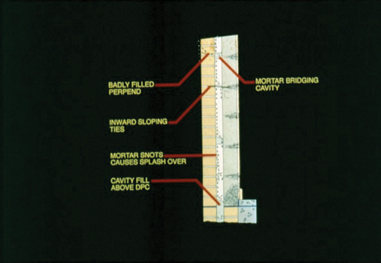
Photo courtesy of Hyload Inc.
Diagram showing problems with badly filled perpends, mortar bridging cavities caused by mortar snots.
Gregory A. Jones, AIA, preservation architect with Hopkins Burns Design Studio, comments, “Historic buildings often totally lack flashing in locations where it would normally be used in modern construction.
“A common flashing issue in historic buildings is the lack of flashing and weeps over steel lintels. Since non-galvanized lintels were typically used in buildings into the mid-20th century, the lack of flashing frequently contributes to a condition known as rust jacking. Moisture that enters walls above lintels has no flashing to protect the lintel and no weeps to direct moisture out of the wall. As a result, moisture collects on the lintel causing it to rust and expand several times its original thickness. This results in expansive forces that can literally lift thousands of pounds of masonry veneer and introduce significant cracking into walls and/or cause spalling of brickwork, as well as deflection of the lintel. Correction of this condition usually consists of replacement of lintels with new galvanized lintels and addition of flashing and weeps to protect the lintel.”
Through-wall flashing is usually adhered to the back-up wall whether it is drywall, insulation, or wood. The cavity between the exterior and back-up wall systems is the “rain plane,” the place where smart design controls moisture penetration.
Notice