Insulated Metal Panels On the Roof


Thermal Performance and Code Compliance
Detailing and air barriers aside, an important aspect of IMP specifications is understanding how its thermal performance characteristics factor into building code compliance.
For starters, insulation requirements are consistently increasing over the past few code cycles. For example, the 2006 IECC’s prescriptive insulation requirements for metal building roofs in ASHRAE 90.1’s Climate Zone 5 include one layer of faced R-19, 6-inch fiberglass batt insulation, draped over purlins, with R-5 thermal blocks at each purlin. The 2009 IECC requires two layers of faced R-13, 4-inch fiberglass batt insulation—for a total of 8 inches in insulation thickness—draped over purlins, with R-5 thermal blocks at each purlin. And the 2012 IECC mandates the same requirements as the 2009 IECC, plus one layer of R-11, 31/2-inch fiberglass batt liner system, installed between purlins, for a total insulation thickness of 91/2 inches, plus thermal blocks.
As a result, continuous insulation—defined as insulation that is continuous across all structural members without thermal bridges, other than fasteners and service openings—is a growing priority with building enclosures.
Offering both continuous insulation and better “material-to-assembly” performance than other systems, when all is said and done, IMPs are a strong option for meeting code compliance.
Helping to promote strong thermal performance is the fact that IMPs are designed to minimize thermal bridging. In particular, the panel faces are separated by a thermal control layer, and the panel mounting clips are attached over the thermal control layer.
Returning to the issue of conforming with the latest building codes, a number of avenues are available to designers, including prescriptive, envelope trade-off, and energy cost budget compliance options.
Starting with the prescriptive approach, where the R/U-values of the components and assemblies are submitted based upon ASHRAE 90.1 tables, IMPs deliver better U-values than most other materials. With single-source responsibility for both the thermal and weather envelope, and the fact that multiple layers of insulation/cavity-filled roofs are not necessary to achieve required insulating values, consequently saves time and money.
For the envelope trade-off option, which permits envelope components/assemblies below code requirements—as long as they are offset by other above-code components/assemblies—IMPs’ exceptional U-values offer the opportunity to “save” on other lower-rated envelope components, such as windows or doors. This also presents greater design flexibility, as specifiers are not locked into certain products or assemblies.
As for the third energy cost budget approach, which allows use of any components/assemblies—as long as the building uses less energy than the prescriptive solution—this supports tradeoffs between envelope and other systems. With the use of IMPs, a high-performing envelope gives more flexibility with the energy consumption levels expected of other building systems.
It’s important to note that the second and third options do require modeling to demonstrate performance-based compliance. Common software programs include eQuest, a user interface for DOE-2 software developed by U.S. Department of Energy, and Energy Plus—a newer DOE program. In terms of IMPs supporting code compliance, MCA has its own IMP technical committee currently investigating ways to directly include IMPs in future ASHRAE 90.1 standards as its own unique construction type.
Other committee activities involve development of an IMP Design Guide with industry-accepted protocols for testing, modeling, and reporting; establishing industry-recognized thermal performance data; and submittal to the International Code Council for inclusion in future IECC cycles.
In the meantime, the IMP industry is working to rectify certain misconceptions amongst designers, such as a common failure to understand that R-values can vary depending on mean temperature, the R-values of IMPs increase in colder climates, and the fact that energy modeling software assumes R-values measured at 75 degrees Fahrenheit. Armed with more accurate information, designers can more effectively compare different insulation systems and better understand the advantages of IMPs in colder climates and cold storage application.
Exploring IMPs
Available in a number of colors, textures, finishes, and sizes, the once industrial-looking metal roof is now capable of offering a nice aesthetic. With a variety of modules (i.e., 30 inches, 36 inches, or 42 inches), thickness ranging from 2 inches to 6 inches, and lengths spanning between 8 feet and 53 feet, architects have the flexibility to design an architecturally appealing roof for a variety of building types.

Available in a variety of modules, thicknesses, and lengths, insulated metal panels lend a nice aesthetic to the building roof.
When the roof panels are combined with IMP wall panels, this not only creates a nice uniform aesthetic, but a compatibility of materials is assured along the all-important roof-to-wall transition and overall building enclosure.
“IMPs have developed from the early ribbed metal-faced panels to now include a variety of smooth and textured metal modular wall panels integrated with reveals, trim, windows, and louvers,” reports Kazba.
In order to stiffen the panel faces, an embossed surface texture is typically applied with various profiles rollformed into them, according to MCA. Profiles commonly include light striations or planking, deep ribbing, or stiffening beads.
Another popular add-in is embossing, which is a process used to create surface texture on metal coils. In addition to masking minor blemishes, such as paint scratches and surface variations, the embossing flattens wavy coils and eliminates the “mirror” effect of smooth finishes. Nondirectional embossing results in a wavy pattern, while directional embossing produces linear lines along the length of the coil.
In terms of the specific material used for the panels, the most common metal substrate for panel faces is G90 galvanized steel, but stainless steel, aluminum-zinc-coated steel, and aluminum are used as well.
For instance, one leading IMP manufacturer adds in a zinc coating to its G90 sheet steel at a thickness of 0.9 ounces per square foot of metal on both sides for corrosion resistance. This creates an approximate thickness of 0.8 millimeter per side.
It’s also worth noting that the composite action between the flat skins and foam core create a structurally sound product. According to MCA, for a 2-inch panel, most wind load requirements in the 20 to 30 psf ranges can be met with 7-foot to 10-foot span conditions. Typically, panel capacity is controlled by the fastener system under negative wind loads.
Describing IMPs as sleek and subtle, when designed properly, Williamson advises selecting fasteners made of the same material to prevent metal corrosion, which could detract from the panels’ visual appeal.
Sharing some additional best practices when it comes to the design of IMP roofing systems, Kazba recommends working with modular dimension layouts coordinated with panel sizes in order to simplify cutting and joinery, and taking advantage of IMPs’ interior surface to eliminate the requirement for interior finishes. For the exterior, designers should specify high-quality finishes to ensure long panel finish life.
For instance, Kynar—made with a high percentage of polyvinylidene fluoride—is a common exterior paint finish, while polyester is a standard paint finish for the interior. For high-humidity interiors, some wash-down areas, and cases where thicker paint film is required, USDA-compliant polyvinyl chloride paint is a good choice. For both finishes, the interior coatings are easy to clean and offer high light reflectivity.
Because the coatings are factory applied and are well-suited for IMPs, the result is a longer life finish, as compared to other exterior system options.
Kazba also advises selecting electrical and datacom distribution techniques that do not require concealment in outside walls and limiting through-roof penetration of building services, for example, going with ground or enclosed space for mechanical equipment, as opposed to roof-mounting, where possible.
Similarly, MCA’s guide states that penetrations should be kept to a minimum. Where required, small penetrations should be sealed with boots or stack flashings. For larger roof penetrations, a factory-welded curb with additional structural support is the most ideal solution.
Overall, Koziol recommends providing shop drawings early in the project, which delineate the more unique details for the particular job outside of the canned, generic details for standard conditions.
He also emphasizes the importance of paying close attention to properly sealing the panel endlap and sidelap joints and seams. These elements should also be detailed and constructed in a way that maintains the same thermal value as the body of the panel, as this will help provide the desired continuous insulation requirements directed by the energy codes.
“Also, be sure to provide detailing that maintains thermal and moisture barrier redundancy at all of the interface details with edge terminations, intersecting walls, and penetrations, especially if the roof geometry is complex or has a low slope of 3:12 or less. Develop detailing that is not reliant on sealant joints alone for water tightness,” states Koziol.
Fortunately, Kazba points out, “Combining IMP roof and wall panels creates a highly sealed condition at the roof/wall joint, something that is more difficult to accomplish with conventional building assemblies.”
When it comes to properly joining the panels, Williamson directs designers to carefully follow the manufacturer’s manual, as this is key to ensuring the functionality of the IMPs. Similarly, the panels must be aligned correctly, as they rely on linear seal technology, and misaligned panels could lead to severe structural problems, which may be difficult and costly to rectify.
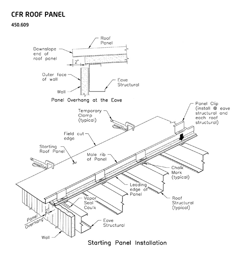

When installing the first panel, leave a 1-inch gap for field-applied insulation.
Offering some direction here, MCA’s guide states that the support alignment should not deviate more than 1/4 inch in any 20-foot length at any direction. In addition, the total alignment envelope should be plus or minus 1/2 inch over the entire panel surface, excluding transition areas, such as building corners and soffit areas where the alignment must be within 1/8 inch of the theoretical girt plane in order to accommodate formed transition or corner panels.
In the case where there is variation in the steel alignment from the theoretical plane, the panels should all be oriented in an outward direction. Alternatively, if one purlin is on the plus side and the adjacent purlin is on the minus side, this can cause stress on the insulated panels at an unacceptable level.
“For example,” says the guide, “an insulated roof panel spanning 5 feet with a deflection limit of L/180 will deflect a maximum of 1/3 inch. If the purlin supporting the panel is designed with the deflection limit of L/240 and spans 25 feet, the allowable deflection for the purlin is 11/4 inches, and this can lead to excessive deflection and stress on both the panels and panel connection.”
As another point of reference, one leading manufacturer’s insulated metal standing seam roof panel installation guide lists the following standard framing alignment tolerances:
- Out of square: 1/4 inch of saw tooth tolerance
- Structure length: An overall +/- 2-inch rake-to-rake tolerance or +/- 1 inch at each rake
- Structure width: An overall +/- 1-inch eave-to-rake tolerance or +/- 1/2 inch at each eave, endlap, and ridge
- Vertical alignment: Vertical deviation from the nominal roof plane of +/- 1/8 inch in any 5-foot length, +/- 1/4 inch in any 20-foot length, and +/- 1/2 inch over the entire roof area
In line with MCA’s cautionary note about tolerances, the manufacturer’s instructions also state that excessive vertical misalignment between adjacent framing members will cause deflection (i.e., bending of the installed panel). This can then create an improper side joint assembly when attempting to install the next panel. Furthermore, a combination of thermal stress and wind stress on the deflected panel may cause buckling of the panel face.
As much is at stake here, in terms of getting the specifications just right, Halle advises the design team not to hesitate getting the manufacturer and installer involved in the design process.
Along these lines, certain design preferences may need to be established with the manufacturer as early as possible, for example, specifying a certain color so that it can be fabricated in a timely manner. Or, in the case where a support system spans from the top of the slab to the underside of the roof assembly, the IMP manufacturer will need to be asked to detail the panels so there is no movement that could damage the panels and the surrounding area, explains Williamson.
Architects should also take advantage of the manufacturer’s expertise to provide training for the installing team.
Here, Koziol points out that the nature of IMP roof systems is such that a higher degree of attention to detail and better-than-average workmanship is required to deliver a high-quality end product. As a result, he recommends the installer be highly experienced and sheet metal roofers are retained to do the flashing details, as opposed to using steel or metal building erectors.
On the same page, BCRA Nexus specifies a minimum five years of successful and documented installation experience on any roofing project.
Notice