Cladding Safety with Metal Composite Material (MCM) and the NFPA 285-19


It’s important to note that the 10-foot vertical heat spread is actually 4 feet because the flames emitting from the window opening due to the gas fire inside the burn room extend 5 to 6 feet above the window opening without the involvement of any combustible materials contained within the wall assembly.
Importance of the Panel Joints And Their Location
A great deal of information has been provided about panel joinery and the required location for the horizontal and vertical panel joint. But why is this so critical in MCM panel assembly?
A technical joint in an MCM system is ½-inch wide. The joint is typically manufactured by closing off the edge of the panel either by folding the MCM at a 90° angle upon itself or by attaching a perimeter extrusion to the MCM panel. Both methods use a faster anchorage system to attach the panel to the substructure. The overall appearance of the ½-inch joint may be one of several different types. While each type of joint provides a different appearance, each joint allows for the fastening of the panel to the substrate and for expansion of the MCM panels subjected to dramatic temperature change.
Probably the simplest panel joint is known as a “wet seal.” The ½-inch gap between panels is still the backer rod and some type of sealant material—in many cases a structural silicone—that provides a smooth finish to the panel and resists the penetration of rainwater.

Photo courtesy of CEI Materials
At the NASA Langley Laboratory in Hampton, Va., aluminum composite material in two distinct finishes serve as flame-retardant rainscreen cladding and helps create a modern look for the aeronautic building.
The other common alternative is an “open joint” or rainscreen joinery system. In this instance, both air and water are allowed to enter the cavity behind the panel and drain out as needed. Often times there will be some type of cover plate or spline plate that will be inserted into this joint to cover the attachment system. While these spline plates provide a desirable appearance, they are not necessarily intended to stop the flow of air and water to the cavity behind them.
Not only do air and water penetrate the exterior cladding layer at the system joinery, it is also considered to be the weakest location in a fire situation. This is the reason for the specific location of the specified vertical and horizontal joint location above the window opening. When the fire exits the window opening, it reattaches to the panel system in the general area where both the vertical and horizontal joint exist. In some cases, the fire has direct access to the cavity behind the cladding which will typically contain insulation. The joinery's direct exposure to the fire, and the fact that the fire is now hidden from view, are important concepts.
Also, the joint depth, and the depth of cavity behind the exterior cladding, is often dictated by the panel attachment system. The details and dimensions of this cavity are important because if the combustible elements of the wall assembly ignite, flame spread through that cavity could go undetected for some time and could progress up the wall assembly.
The NFPA 285 test is designed not only to measure the flame spread up the exterior side of the exterior cladding; it is also designed to measure the flame spread that takes place within the cavity between the interior face of the exterior cladding and the exterior sheathing. Any elements within this cavity that are combustible must also meet the performance criteria required for the entire wall assembly.
So, the panel joints provide potential access to the internal wall assembly elements without the benefit of protection from the exterior cladding, which in the case of MCM, consists of a metal surface that reflects the flames and heat for a period of time.
Composite Materials with a Flame-retardant Core
In terms of why MCMs with an FR core perform well when subjected to NFPA’s increased stringencies, it is helpful to understand how the material is manufactured. First, an extruded core material is produced and then a metal coil is applied. These two components are bonded together through the controlled application of heat, pressure, and tension. Next, the bonded sheet is cooled in a controlled process to maintain the bond integrity and flatness.
When exposed to fire, the metal skins initially deflect the heat and fire away from the combustible core of the panel. While the metal skins will eventually melt, the material remains in place, and the metal limits both the amount of combustible core available to the fire and the spread of flame.
Also of note is the fact that wall cavity heat gain is not typically an issue in MCM systems in the absence of exterior flames. In other words, the wall does not self-sustain the flame after burners are turned off. Thanks to its FR core, the wall self-extinguishes almost immediately.
In addition to a certain level of flame retardancy, the metal skin provides structural stability for the panel and can be finished in a number of colors and finish types. Incidentally, the IBC requires a minimum thickness of 0.019 inches as a weather covering to resist normal exposure without significant visual damage.
Weather-Resistive Barriers
As noted, all combustible components in combination must be considered when determining if a wall assembly meets NFPA requirements. In addition to combustible cladding material, this includes certain types of WRBs and insulation.
WRB product options vary by their application method and base chemistry. The chemistry and required thickness of combustible weather barriers contribute to the product’s level of fire performance.
WRBs come in different types: fluid-applied, self-adhering sheets, or mechanically fastened sheets. In general, the fluid-applied WRBs are more difficult to control in thickness and have the potential to provide more combustible fuel than the sheet goods. Consequently, when the WRB exceeds the peak heat release of 150 KW/m2, and the WRB is the only combustible in the wall assembly, then an NFPA 285 test is required.
Bituminous coatings, which are rubberized asphalts, are fluid-applied weather- and air-barrier products. Typical applications are thick, up to 100 mils or more, and have been associated with problems including cracking, wrinkling, blistering, and melting. More significant is the fact that asphalt-based membranes tend to exceed the 150 KW/m2 threshold and can perform poorly in the NFPA 285 flammability test.
It should be noted that spray-applied weather-barrier applications may not provide a controlled thickness, as is the case with premanufactured sheet goods. This could mean varying amounts of combustible materials on the wall. Also, the difference between a mechanically attached (i.e., staple- or cap nail-applied) and an adhesively applied weather barrier can introduce additional combustibles in the form of the adhesive material.
In his experience, Nelson relates, “The following WRBs generally contribute minimally to fire propagation and can provide robust performance: silicone fluid-applied, STPe fluid-applied, and commercial grade spun-bonded polyolefin. These are all recommended to comply with ASTM E2357, though it’s important to follow their manufacturer’s high-performance recommendations.”
The fact that the WRB can be specified in various locations (i.e., behind, or in front of, the insulation, and in some cases, both), and that each orientation can affect the fire performance of the wall assembly differently, underscores the importance of testing the wall as a full assembly, per NFPA 285 requirements.
The specific combustible limits of WRBs, when it is the only combustible in the wall assembly, are detailed in Chapter 14 of the IBC and determine where NFPA 285 is required. In addition, architects and engineers can better understand fire performance, and which products have successfully passed NFPA 285, by reviewing test reports, certification reports, and/or engineering judgments.
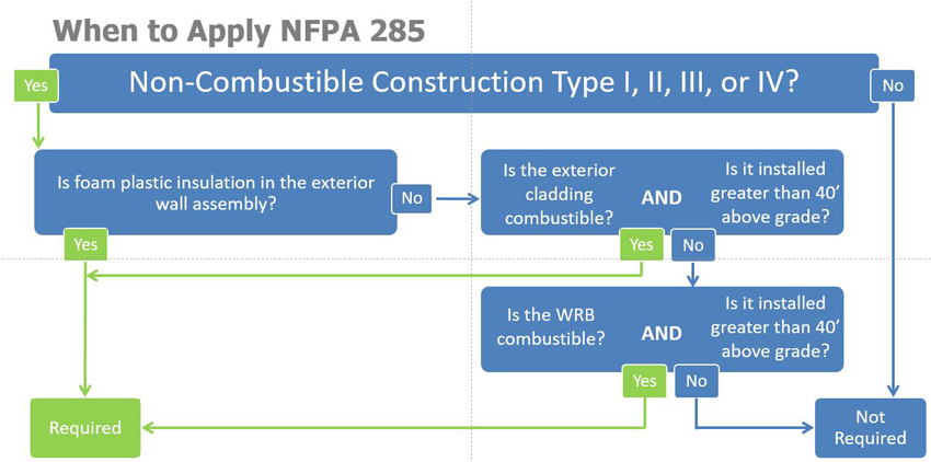
Image courtesy of Metal Construction Association
By applying a number of questions, project teams can determine if their exterior wall design requires an NFPA 285 test.
Notice