HVAC for Large Spaces: The Sustainable Benefits of HVLS (High Volume/Low Speed) Fans


CFM ratings
The amount of air that passes through the swept area of a fan is measured as a volume of air over a period of time, usually expressed in cubic feet per minute, or CFM. This metric is generally referred to as CFM for the sake of convenience and consistency. Measuring the CFM of a very large-diameter fan is challenging because of its sheer size and the low pressures created by HVLS fans. The accepted method of obtaining this performance measurement is to measure the thrust, or force the fan produces as a reaction to the air it is moving, and use a formula to convert that number to CFM. In order to measure thrust, an apparatus that measures force, must be installed between the fan and its mounting point on a structure. As most manufacturers build their own testing equipment, their results can vary, sometimes widely.
| Air Performance Certified Ratings |
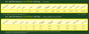 |
Click on image to see details, (PDF). |
AMCA, a non-profit international association of air system equipment manufacturers, measures and certifies the performance of all types of air moving equipment, including HVLS fans. They have built equipment especially for measuring the thrust of large HVLS fans, following ANSI's testing guidelines. Some HVLS manufacturers have hired AMCA to test their fans' performance and certify those 12 feet in diameter and below. Unfortunately, larger fans cannot be certified because to meet ANSI requirements, such certification would require a room whose length and width would each be twice the diameter of the fan, and AMCA's testing facility lacks a large enough room to certify fans larger than 12 feet in diameter.
Different manufacturers describe the performance of their fans in different ways. Some use measured thrust value, converted CFM value, and/or AMCA certified values when listing their fans' airflow. Others do not describe how their fans' performance is measured. When evaluating HVLS fan performance, it is important to consider how much effort a manufacturer has made to ensure that their numbers are accurate.
Airfoil blade design
The original HVLS fans had ten blades manufactured from extruded aluminum. Recent developments have been made to reduce the number of blades (to six, for example) and improve their design. One such redesigned airfoil blade has all the properties and attributes of the original design with the addition of an anodized finish, which increases surface tension and makes the surface less porous and therefore resistant to corrosion. It also has a much longer chord length that yields more air flow and higher mechanical efficiencies. (The ‘chord' is a line that touches the circumference of an imaginary circle drawn around the profile of a fan blade in its installed position at two points. The longest chord length is from the leading edge of the blade to the trailing edge of the blade and represents the surface that moves air.)
EMI and RFI compliancy
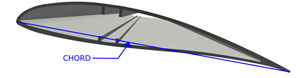 |
Example of hollow extruded aluminum airfoil blade used in recent HVLS models has a longer chord length than earlier models. Image courtesy of MacroAir Technologies |
Just as electromagnetic energy radiated by laptops and personal digital devices might interfere with an airliner's avionics, so design professionals should be aware of the potential for electromagnetic interference (EMI) or radio frequency interference (RFI) from HVLS fans. Unless several steps are taken to reduce the EMI or RFI produced by a fan's controller and motor, they have the potential for disrupting any or all electronic systems within a building. Because virtually all facilities rely on some level of computerization, any interference could have serious repercussions. These steps include using an input filter on the controller, using shielded motor cable between the controller and the fan, and reducing the length of the cable run between the controller and the fan (which also increases the life of the fan's motor and gearbox). The best solution is to use fans from manufacturers who have taken these steps for the customer, making their standard package compliant. Retrofitting a non-compliant installation can be difficult and costly, and doing so can risk losing the warranty due to controller modification. Paying extra for optional equipment drives up the price of the fan, and adding non-standard equipment can also increase installation costs. With this in mind, design professionals should ask manufacturers if their fans as sold are compliant with worldwide RFI and EMI standards and FCC part #15 legislation or whether optional additional equipment is needed to achieve compliancy.
Solidity Ratio
From an engineer's perspective, fans are viewed in plan and in motion. They appear as a disc - known as a ‘rotor disc' - where blade and hub are indistinguishable. ‘Solidity ratio' refers to the obstruction potential of the rotor disc and is determined by the total area of the blades and the width of the blades plus the size of the solid hub section (the ‘solid' component of the rotor disc) compared with the total area of the rotor disc. In general, if the fan has more blades and/or its blades are wide, its solidity ratio is higher. If a fan has fewer blades and/or the blades are narrow extrusions, its solidity ratio is lower.
The NFPA provides very specific guidelines regarding potential fire sprinkler obstructions, including moving HVLS fans. While research and testing are currently being conducted to determine if these rules need to be changed, they will no doubt continue to be an important consideration when selecting fans. The solidity ratio of a fan is a major component of the NFPA guidelines; therefore, since fans with lower solidity ratios offer less potential sprinkler obstruction, they are preferred to fans with higher solidity ratios. Published solidity ratios vary from approximately 30 percent to 70 percent, so design professionals should check with manufacturers to learn the solidity ratios for particular models (NFPA research is available at www.nfpa.org/assets/files//PDF/Research/HVLS.pdf).
Notice