Noise Reduction in HVAC Duct Systems


Terminal End Reflection
Terminal end reflection is effective for attenuating low frequency energy. At the termination of a duct path, a portion of low frequency power wave energy is reflected back into the duct.
Table 14A. Duct end reflection loss when duct is terminated in free space.
 |
|
Provided by Kinetics Noise Control, Inc. |
End reflection attenuation is virtually negated if a variable air volume (VAV) system, diffuser/grille is placed at the duct opening.
Airflow-Generated Noise
Air flowing over duct surfaces generates noise. The following airflow conditions should be avoided:
* High face velocities:
Greater than 2,000 ft/min for rectangular duct
Greater than 3,000 ft/min for round and flat oval duct
It is recommended that acoustic analysis calculations include airflow-generated noise for all duct elements, along the critical path. This includes the sound power levels of fan powered VAV boxes. Generated sound power levels should be compared to the resultant levels after subtracting all pertinent attenuation. If they are within 10 dB of the resultant value of any octave band, they will contribute to the overall noise level.
Radiated “Break-out” Duct Noise
“Break-out” noise is noise that radiates from the duct system elements to surrounding spaces. It is an important design parameter whenever a duct system runs through or over an acoustically sensitive space. This noise will most likely be a problem if the localized in-duct sound power level at any frequency, minus the duct wall transmission loss, exceeds or is within 3 to 5 dB of the NC level of the acoustically sensitive space. This is best addressed during the initial design of the duct system.
“Break-in” Noise
Ambient noise transmitted into a duct is known as “break-in” noise. This noise can be ignored if in-duct noise is 10dB or greater than the break-in noise. But at places where the fan and aerodynamically generated noise are minimal, significant levels of break-in sound can radiate from surrounding areas to inside the duct and propagate to critical places along the duct path.
Room Acoustics
After logarithmically combining the attenuated sound power levels with the airflow generated sound power levels, the next step is to determine the sound pressure levels within the critical space (i.e. office, conference room, sanctuary, etc.). This is done by taking the sound power levels remaining at the supply air diffuser or return air grille and converting them to sound pressure—taking into account the acoustic effects of the room (i.e. sound absorption and sound reflection). The resulting sound pressure levels will be used to determine whether HVAC sound is within acceptable/specified design criteria, or if attenuating strategies need to be employed.
Air Terminal Noise
Duct system paths generally terminate at a register, diffuser, grille or other device. Because terminal devices generate noise as a result of air passing across them, it is necessary to calculate the sound power level of that noise before addressing the entire room duct system. Noise generated from diffusers/grilles is critical because it is the last noise source that affects sound levels in the critical space.
Acoustic and airflow test data are usually generated in accordance with ASHRAE Standard 70 “Method for Testing for Rating the Performance of Air Outlets and Inlets.” If the diffuser sound power is within 10 dB of the residual sound power in the duct, it will increase the sound power level emitted in the space.
ASHRAE Room Effect Equation
As mentioned, sound power levels (Lw) and sound pressure levels (Lp) cannot be directly combined. Therefore, in order to calculate sound pressure levels resulting from sound power emanating from HVAC duct terminals, a procedure endorsed by ASHRAE may be used. The procedure assumes that rooms have normal sound-absorbing surfaces and furnishings. Other formulas are available for special rooms (i.e., rooms that are more absorptive, “recording studios” or rooms that are more reflective, “gymnasiums”).
Design Criteria
Having accounted for fan sound power levels, natural duct and fitting attenuations, generated duct, fitting and terminal noise, and converting sound power levels to sound pressure levels for a specific space, the next stage is to determine whether the sound pressure level meets the acoustic design criteria. Various criteria have been established for different space occupancy situations.
Indoor Noise Criteria (NC)
NC curves establish the desirable background sound pressure levels in a critical space. Because higher frequencies are perceived louder than lower frequencies of the same dB level, NC curves allow higher dB levels at lower frequencies. The NC criteria consist of a family of curves that define the maximum allowable octave-band sound pressure level corresponding to a chosen NC design goal. They primarily apply to the noise produced by a ventilation system, but they may be applied to other noise sources.
Measured Lps within a critical space can be plotted against standard NC curves to determine compliance with specification or to rate the noise within the critical space. The appropriate NC curve for a given space is that lowest NC curve that is closest to the highest noise spectrum sound pressure level at a particular frequency.
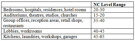
Table 15. Typical indoor design acoustical goals using NC curves
 |
|
Provided by Kinetics Noise Control, Inc. |
NC Curve Plot
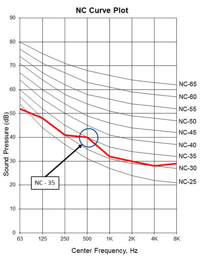 |
Allowable Sound Pressure Level (dB) per Frequency vs. NC Level Provided by Kinetics Noise Control, Inc. |
Notice