


Just Released

Water Leak Detection in Commercial Buildings
Using the latest technology avoids significant costs and harm to people and property
Sponsored By WATTS Water Technologies, Inc.
Credits: AIA, ICC
Type: Article
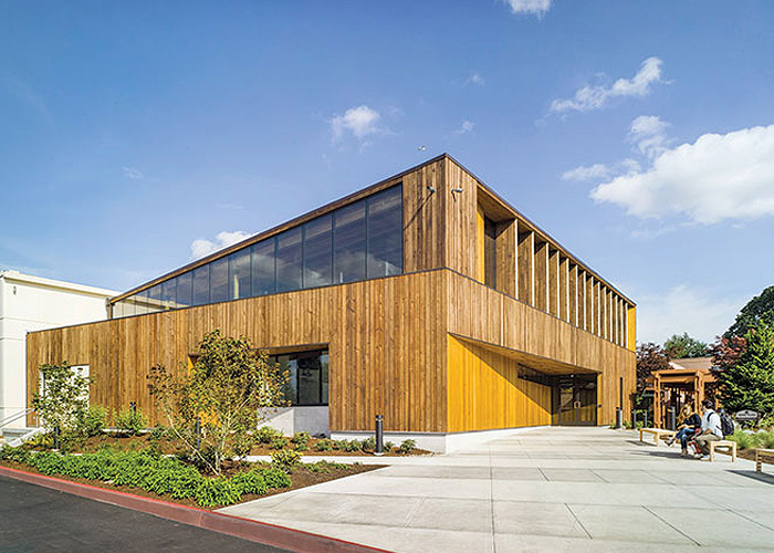
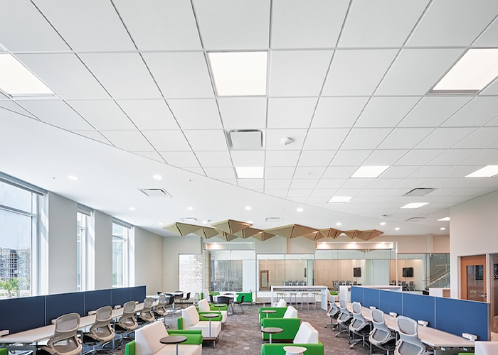
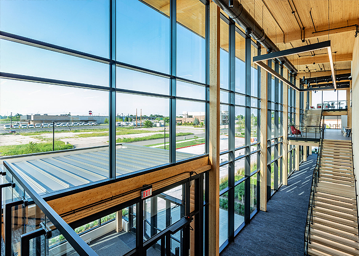
Opportunities For Wood in Low-Rise Commercial Buildings
A versatile and economical approach to large openings, tall walls, and open floor plans
Sponsored By Think Wood
Credits: AIA, ICC, IDCEC
Type: Article

Hybrid Propane Systems
Strengthening residential HVAC systems through hybridization
Sponsored By PROPANE Energy for Everyone
Credits: AIA, GBCI, ICC
Type: Article
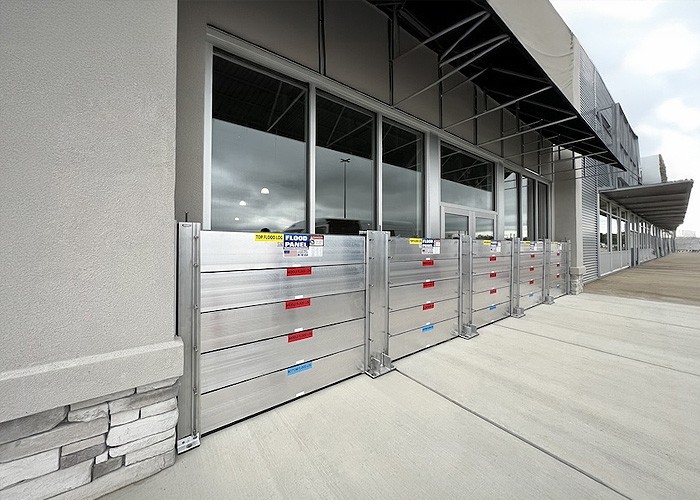
Floodproofing Design Techniques and Code Regulations
The potential risk associated with building in the floodplain
Sponsored By Floodproofing.com
Credits: AIA, GBCI, ICC
Type: Multimedia
Upcoming Webinars

Modified Bitumen Roof Assemblies: Where Old Meets New
Credits: AIA, ICC
Type: Webinar
Feb 12 2025 2:00 PM EST

Built to Protect
Credits: AIA
Type: Webinar
Feb 12 2025 2:00 PM EST

Electronic Leak Detection for Roofing, Waterproofing and the Building Envelope
Credits: AIA, ICC
Type: Webinar
Feb 25 2025 2:00 PM EST

Fire-rated Expansion Joints
Credits: AIA, ICC
Type: Webinar
Mar 12 2025 2:00 PM EST

Next-Gen Leadership
Credits: AIA
Type: Webinar
Mar 13 2025 2:00 PM EST
Going Seamless: The What, Where & Why of Liquid Applied Roofing
Credits: AIA, ICC
Type: Webinar
Mar 18 2025 2:00 PM EST
Competitive, Constructible, Complete Specifying Total Envelope Solutions in a Low-Bid World
Credits: AIA, ICC
Type: Webinar
Mar 19 2025 2:00 PM EST
Pitfalls and Challenges of NFPA 285 Engineering Analysis
Credits: AIA, ICC
Type: Webinar
Mar 20 2025 11:00 AM EST
The Critical Aspect of Air and Water-Resistant Barriers Within the Building Envelope
Credits: AIA, ICC
Type: Webinar
Mar 20 2025 1:00 PM EST

Adaptive Reuse Transformations: Train Stations, Towers, and Hockey Arenas
Credits: AIA, ICC
Type: Webinar
Mar 26 2025 2:00 PM EST

Building Envelope Systems: Tie-ins, Transitions, and Continuity
Credits: AIA
Type: Webinar
Mar 27 2025 2:00 PM EST
Editorial
Joost Moolhuijzen
Credits: AIA
Type: Podcast
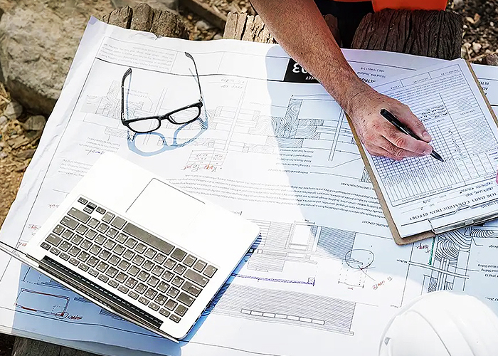
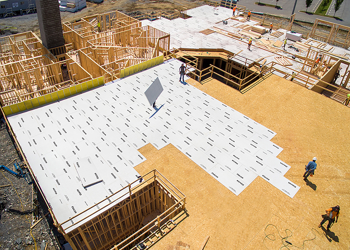
Prefabrication
Credits: AIA
Type: Article

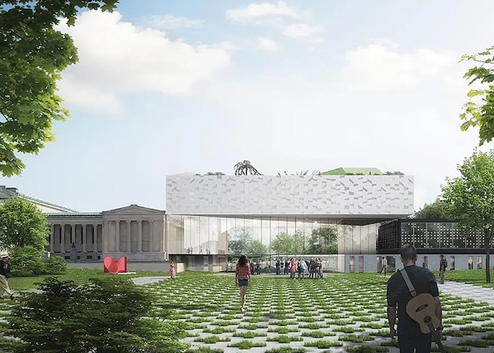
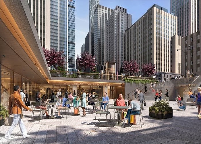
Remaking the Met
Credits: AIA
Type: Article

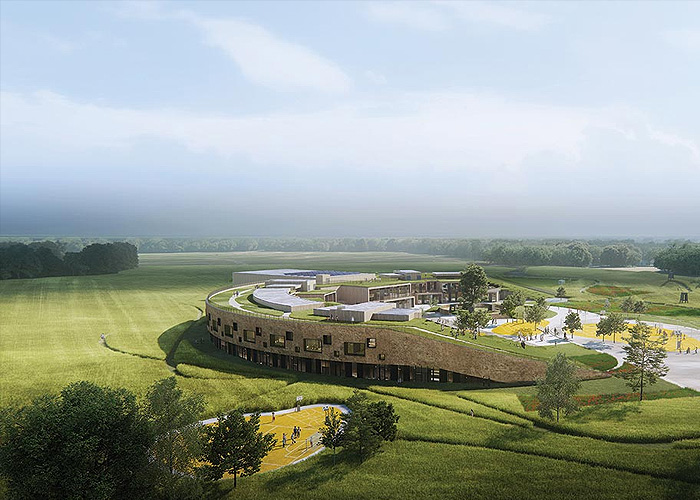
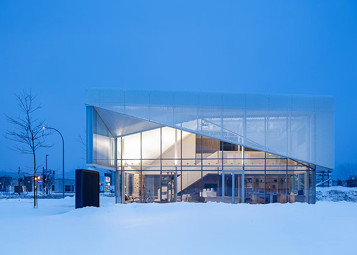
High-Performance Landscapes
Credits: AIA, ICC
Type: Article
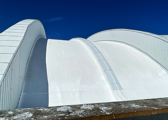
Choosing the Right Waterproofing System
Credits: AIA, ICC
Type: Article
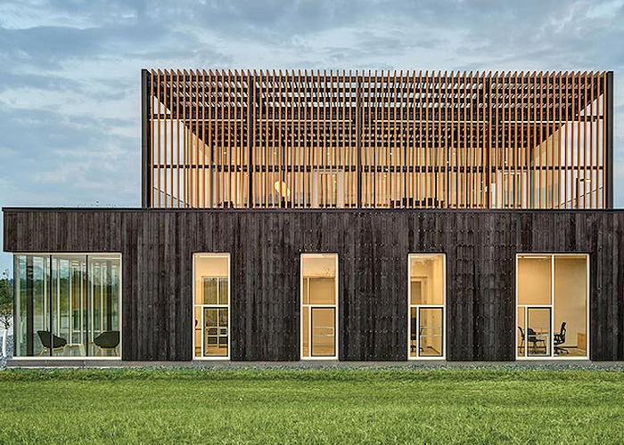
Bio-Based Materials
Credits: AIA, ICC
Type: Article
.jpg)
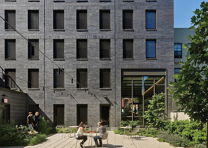
Circular Construction
Credits: AIA, ICC
Type: Article
Taking Care of the Customer
Credits: AIA, ICC
Type: Article
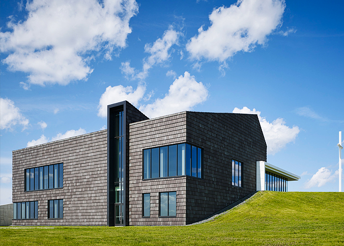
Affordable Housing & Energy Performance
Credits: AIA, ICC
Type: Article

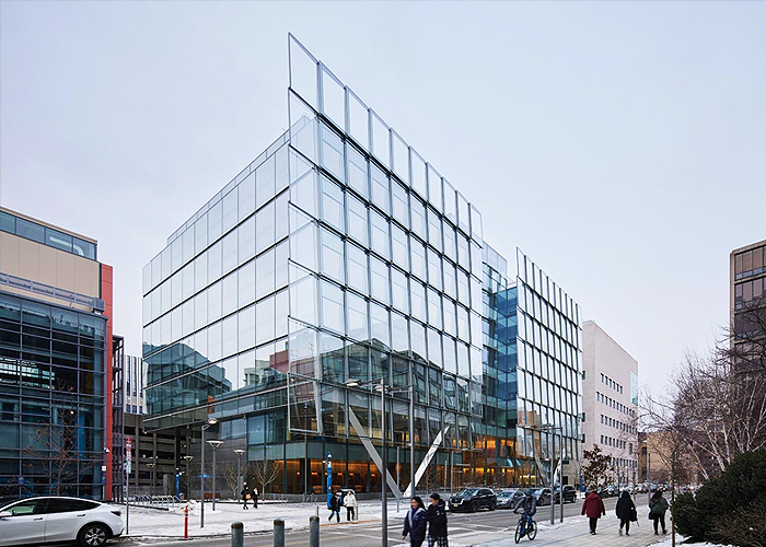
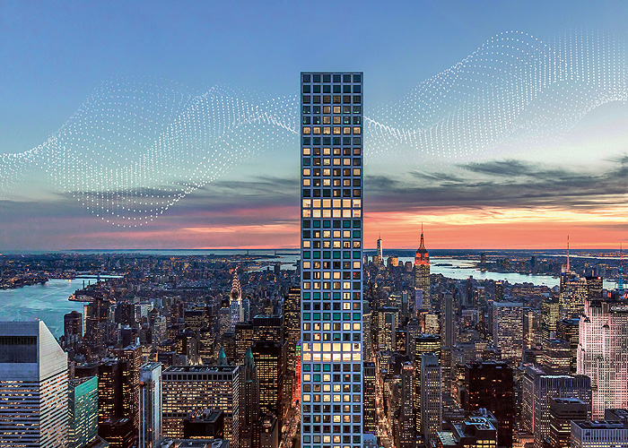
Tall Buildings
Credits: AIA, ICC
Type: Article

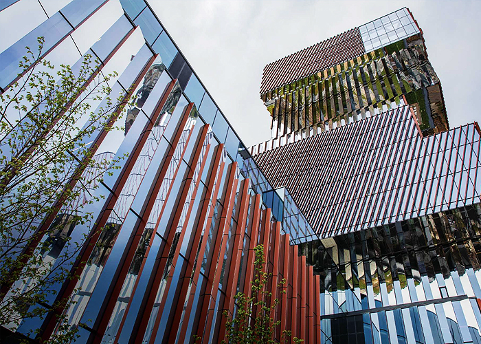
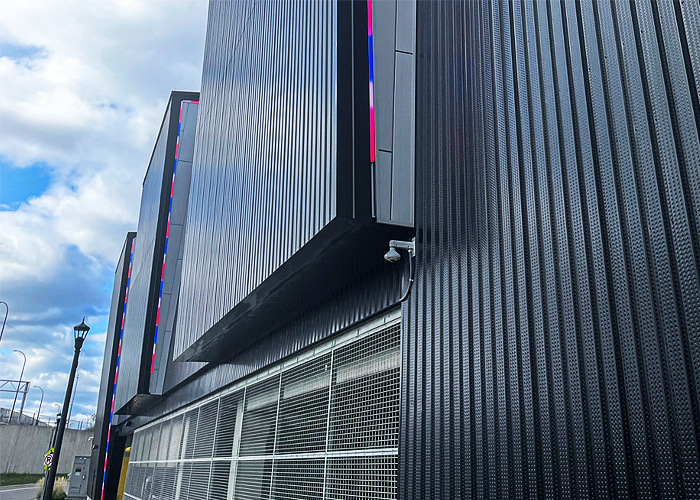
Building Recladding
Credits: AIA, ICC
Type: Article
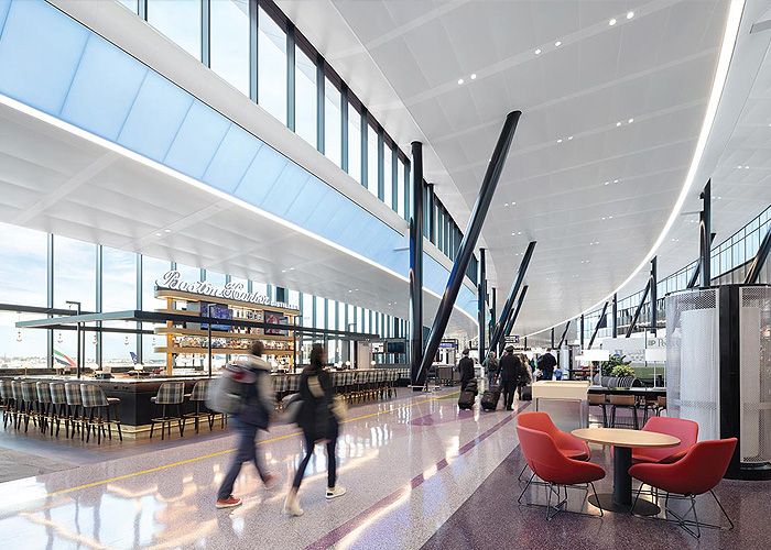
Transportation & Infrastructure
Credits: AIA, ICC
Type: Article

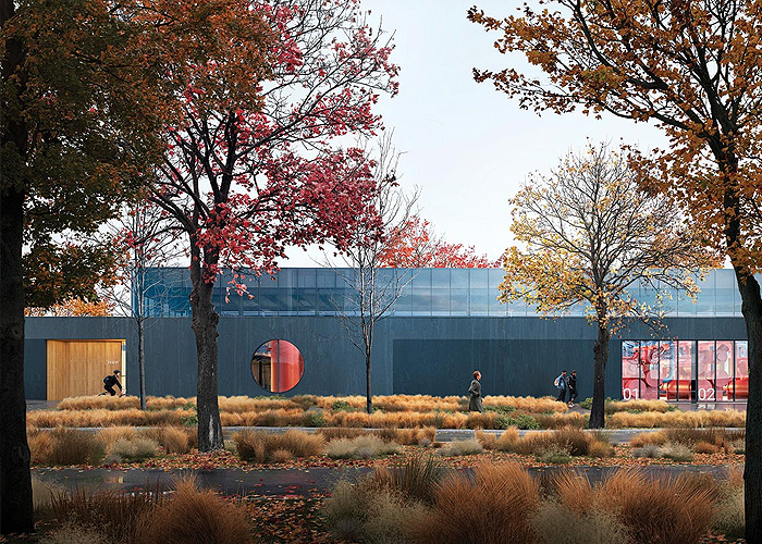
Daylighting in Museums
Credits: AIA, ICC
Type: Article
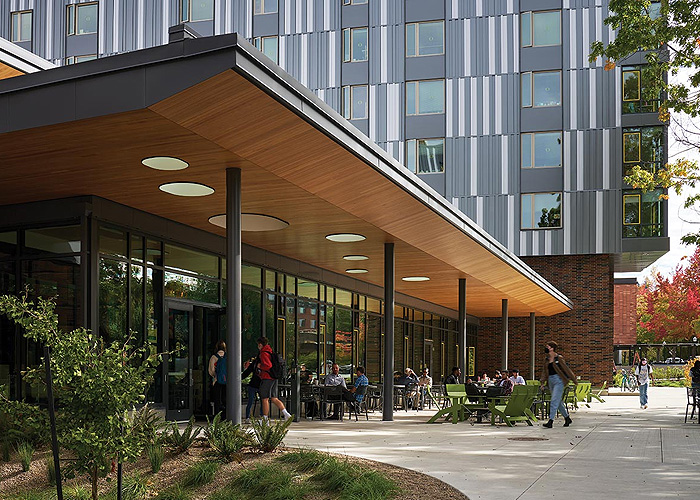
Campus Geo-Exchange Systems
Credits: AIA, ICC
Type: Article

Office Conversions
Credits: AIA
Type: Article
Extreme Heat
Credits: AIA
Type: Article
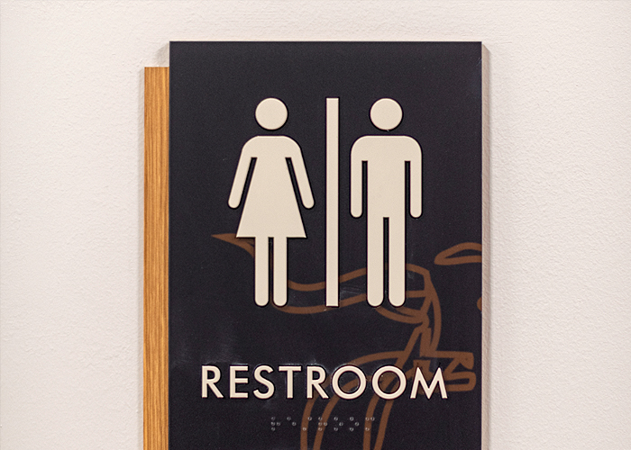
Accessibility
Fully Integrated Health Care Solutions: The Restroom and Beyond
Credits: AIA, ICC
Type: Multimedia

Designing Smarter Restrooms for Education
Credits: AIA, ICC
Type: Multimedia

ADA - Accessibility in Toilet Room Design
Credits: AIA, ICC
Type: Multimedia

Design Trends in Commercial Washrooms and Locker Facilities
Credits: AIA, ICC
Type: Multimedia
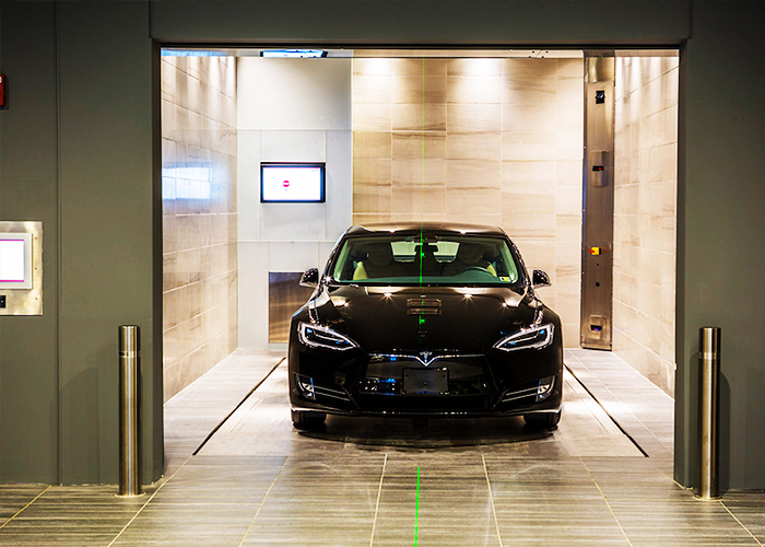
The Sustainability of Automated Parking with EV Charging
Credits: AIA
Type: Article

Wellness-Based Design Strategies in Healthcare
Credits: AIA, GBCI, ICC
Type: Article

INCLUSIVITY: People, Public Furniture, and Public Space
Credits: AIA, GBCI, ICC
Type: Article

Tatiana Bilbao - Tatiana Bilbao Estudio
Credits: AIA
Type: Podcast
Navigating Compliance with ADA Signage
Credits: AIA, ICC
Type: Webinar On-Demand

Brian Korte-Clayton Korte
Credits: AIA
Type: Podcast

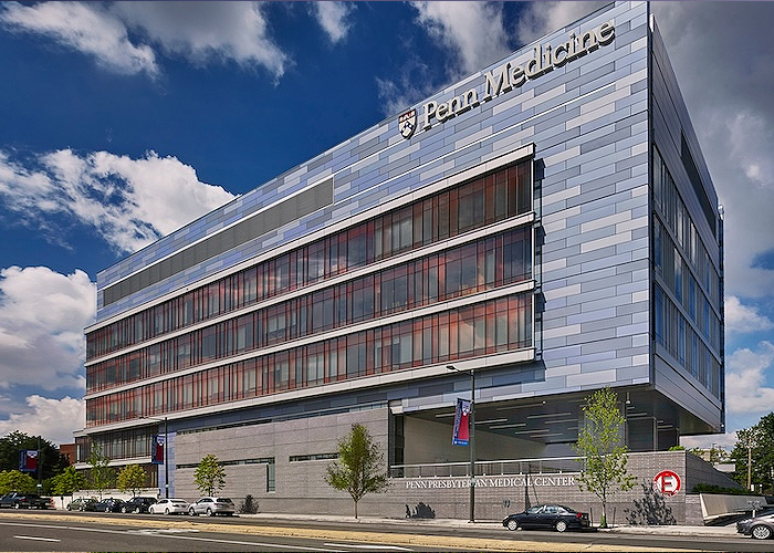
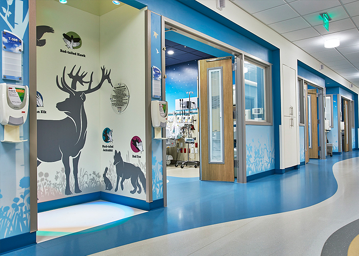
Health Care Design
Credits: AIA, ICC
Type: Article

Designing ADA-compliant Commercial Showers & Bathrooms
Credits: AIA, ICC
Type: Webinar On-Demand
Creating a Safe Haven in Educational Buildings
Credits: AIA, GBCI, ICC
Type: Article
Sit, Stand, Move, Repeat
Credits: AIA, GBCI, ICC, IDCEC
Type: Multimedia
Built to Protect
Credits: AIA, ICC
Type: Webinar On-Demand

Get Smart with Windows, Doors and Skylights!
Credits: AIA
Type: Multimedia
Acoustics

Beyond the Noise: Elevating Building Design, Performance and Experience with Acoustics
Credits: AIA
Type: Article

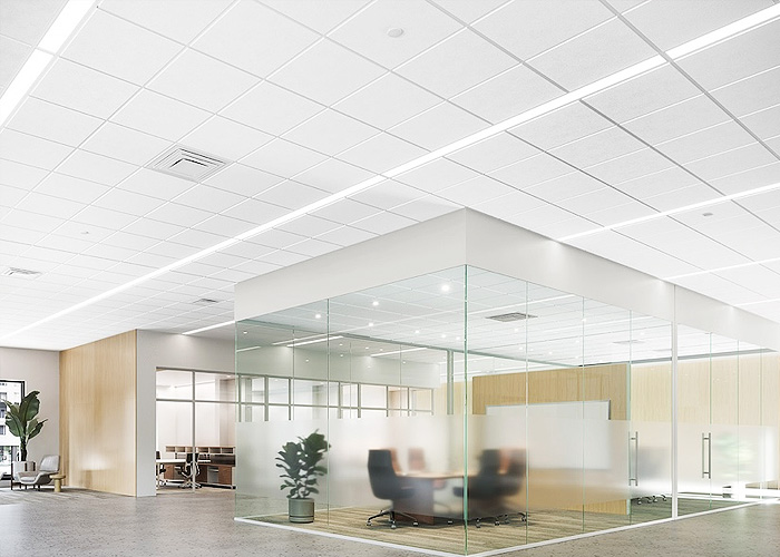
Focus on Facility Guidelines Institute Ceilings
Credits: AIA, ICC
Type: Article

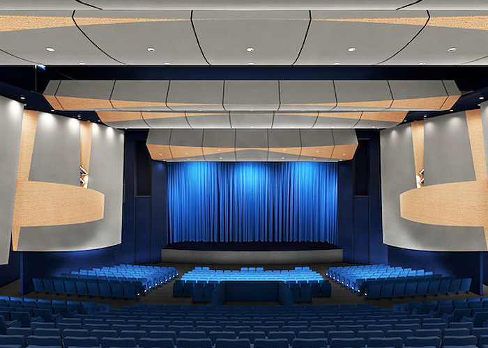
Sonic Shangri-la – The Art of Sound
Credits: AIA, ICC
Type: Webinar On-Demand

Acoustic and Aesthetic Suspended Ceiling Solutions Using Stone Wool
Credits: AIA, ICC, IDCEC
Type: Multimedia

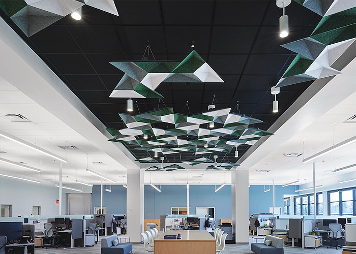
Custom Ceiling Design
Credits: AIA, GBCI, ICC
Type: Article

Healthy Spaces for Healing Environments
Credits: AIA, ICC
Type: Webinar On-Demand
Get Smart with Windows, Doors and Skylights!
Credits: AIA
Type: Multimedia
Harmonizing Spaces
Credits: AIA
Type: Webinar On-Demand
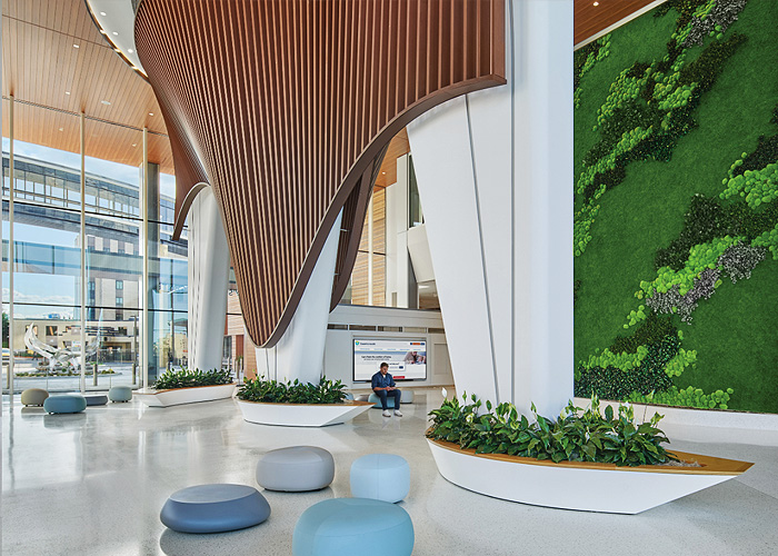
Unveiling the Vital Role of Material Health in Preserved Gardens and Moss Walls: An Introductory Overview
Credits: AIA, GBCI, ICC
Type: Multimedia

Designing Smarter Places of Learning
Credits: AIA, ICC
Type: Webinar On-Demand
The New Era of Acoustical Design
Credits: AIA, ICC
Type: Webinar On-Demand

Acoustical Design for Today's Buildings
Credits: AIA, GBCI, ICC
Type: Multimedia

From Survive to Thrive: Buildings that Enrich Health and Wellness
Credits: AIA, GBCI, ICC
Type: Article
Patricia Viel, ACPV Architects
Credits: AIA
Type: Podcast

Living with Neighbors
Credits: AIA, ICC
Type: Article
Managing Sound In the Wide Open Spaces
Credits: AIA, ICC
Type: Webinar On-Demand
Building Envelope Design
Expanded Metal and Perforated Mesh Interior and Exterior Applications
Credits: AIA, ICC
Type: Webinar On-Demand

Using Charred Wood for Exteriors and Interiors
Credits: AIA, GBCI, ICC
Type: Article
Picking the Proper Mortar for Adhered Veneers
Credits: AIA, GBCI, ICC
Type: Article
The Sustainability of Automated Parking with EV Charging
Credits: AIA
Type: Article
Versatility of Design and LEED Certification with Metal Composite Materials
Credits: AIA, GBCI, ICC
Type: Article

Insulated Metal Panels for Wall and Roofing Retrofits
Credits: AIA, GBCI, ICC
Type: Article

Profiles in Multifamily Innovation
Credits: AIA, GBCI, ICC
Type: Article
Building Technology
Credits: AIA, ICC
Type: Article

Using Metal to Achieve Aesthetics and Performance
Credits: AIA, ICC
Type: Multimedia

Time to Rethink Affordability
Credits: AIA, ICC
Type: Webinar On-Demand
Magnesium Oxide (MgO) Floor Panels for Multifamily Buildings
Credits: AIA, ICC
Type: Webinar On-Demand
Architecture and Terra Cotta Cladding
Credits: AIA, ICC
Type: Webinar On-Demand

Leveraging High-Efficiency Propane Systems Leveraging in Zero Net Energy Homes
Credits: AIA, GBCI, ICC
Type: Multimedia
Climate Resilient Building Design: Optimizing Temperature Control and Energy Efficiency
Credits: AIA, GBCI, ICC
Type: Multimedia
Next-Level Glass Performance and Sustainability
Credits: AIA
Type: Article
Reducing Operational Carbon Emissions and Increasing Energy Efficiency with Solar Air Heating
Credits: AIA, GBCI, ICC
Type: Webinar On-Demand
Electrical and Mechanical

Heating Oil Conversion
Credits: AIA, GBCI, ICC
Type: Multimedia
The Sustainability of Automated Parking with EV Charging
Credits: AIA
Type: Article

Meeting Energy Demands While Facing the Challenges of Electric Grid Instability
Credits: AIA, GBCI, ICC
Type: Article

Propane and Building Design for Commercial Businesses
Credits: AIA, GBCI, ICC
Type: Multimedia

Propane Gas Systems
Credits: AIA, GBCI, ICC
Type: Multimedia

Human-Centric Lighting Made Simple with Automation
Credits: AIA, GBCI, ICC
Type: Article

Controls Optimization for Residential Heating Systems for New and Retrofit Homes
Credits: AIA, ICC
Type: Webinar On-Demand

Propane-Enabled Solutions for Commercial Buildings in Rural Areas
Credits: AIA, GBCI, ICC
Type: Multimedia

Energy Efficiency and Resilience of Building and Renovating With Propane
Credits: AIA, GBCI, ICC
Type: Article
Building for the Future: Digitally Connected Elevators
Credits: AIA, ICC
Type: Webinar On-Demand

Roof Hatches Simplified
Credits: AIA, ICC
Type: Article

Keeping Pace with Technology
Credits: AIA, ICC
Type: Webinar On-Demand
Get Smart with Windows, Doors and Skylights!
Credits: AIA
Type: Multimedia
The Future of Hot Water in Commercial Operations
Credits: AIA, ICC
Type: Article

Achieve Acoustic Excellence: Design Strategies that Affect STC Ratings
Credits: AIA, ICC
Type: Podcast

Designed for Life
Credits: AIA, ICC
Type: Multimedia