This CE Center article is no longer eligible for receiving credits.
A cross all 50 of the United States, and in many countries around the world, model building codes have been adopted that are developed by the International Code Council (ICC). Referred to as the International Codes or I-Codes, they include a coordinated family of building safety codes, such as the International Building Code (IBC), the International Residential Code (IRC), the International Energy Conservation Code (IECC), and 12 other specialty codes. All of these documents are the result of a very comprehensive, ongoing process to review, assess, and update them using a three-year cyclical process. There are literally tens of thousands of people involved through this very transparent method that the ICC terms a “governmental consensus process.” It points out that this “process leaves the final determination of code provisions in the hands of public safety officials who, with no vested financial interest, can legitimately represent the public interest.” In this course, we look at the code development and updating process with an eye toward the role that design professionals, code enforcement officials, the construction industry, and material suppliers all play. We also delve into some specific examples of code-defined issues related to the building envelope and energy conservation. The intent is to provide a broader understanding of how the I-Codes can be an effective tool for staying up-to-date on how buildings can best promote the health, safety, and welfare of the occupants, users, and general public.
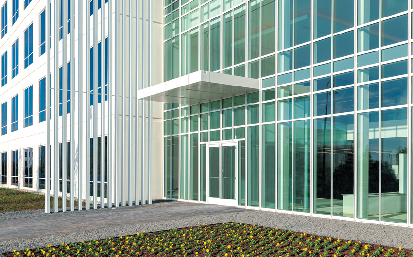
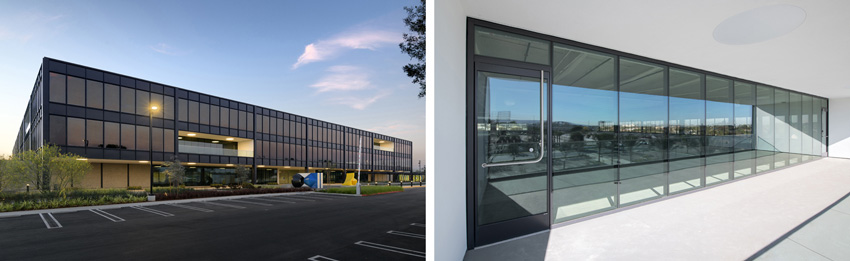
Photo courtesy of GFF Architects
Building and energy codes directly affect the design of all buildings, particularly their exterior walls and entrances.
Code Development Process
How does a change come about to the codes? Ultimately, it starts with the 64,000 members of the ICC. Memberships are categorized by Individuals, Corporate, Governmental, and Associates, each of which carry corresponding benefits and voting rights. Not surprisingly, a substantial portion of the members are code enforcement officials or staff of jurisdictions having authority to enforce the codes. Members also include design professionals (architects, engineers, etc.), corporations (both non-profit and for-prof it), construction companies, product manufacturers, and others with a direct interest in the codes. In addition, a professional ICC staff of 500 employees across nine offices manages and maintains the workings of the ICC as directed by its governing Board. The typical three-year-long process that is used by all of these people to change or update the codes is outlined as follows.
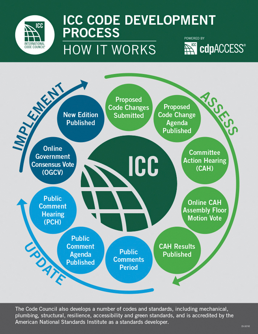
Source: International Code Council
The International Code Council (ICC) code development process requires a three-year cycle for updates.
Stage One: Code Development Committees
Anyone can apply to serve on one of the code development committees, with applications reviewed by the Codes and Standards Council. Final recommendations are made to the ICC Board for appointment. Members of the committees fall into any one of three categories: 1) general members, including governmental regulatory agencies; 2) users such as building owners, design professionals, insurance companies, private inspection agencies, and academics; or 3) producers, meaning builders, contractors, manufacturers, and distributors. The committees are typically broken down by specialty topics related to the I-Codes, and it is the role of the committee members to bring their expertise and professional knowledge into the discussion and review of their code-related topics.
Changes or updates to any of the I-Codes can be proposed by anyone using an online platform known as cdpACCESS. ICC staff members monitor and review such proposals and assign them to the appropriate Code Development Committee. It has been observed that market forces, design advances, product research and development, academic research, and other factors often cause changes in the design and construction field to happen first. As these changes become more commonplace, the I-Codes need to be kept up-to-date to address them appropriately. Hence, it is ultimately the charge of the committees to keep the I-Codes updated and relevant to the design and construction industry while continuing to safeguard public health, safety, and welfare.
Stage Two: Committee and Public Hearings
With committees in place and proposals received, the process of review begins with Committee Action Hearings. Using an inclusive series of presentations, discussion, and debate, the committee delves into the details of the proposed change and its impact on the codes. Upon completion, the committee then votes on each proposal in one of three ways: approve, approve with modification, or disapprove. In the first two cases, the proposal will move forward for public review, while a disapproved proposal typically ends there. However, any participant in a particular proposal process can challenge the committee actions. In that case, ICC members can vote on the challenge online and, if approved by voting, the proposal automatically moves forward to public review.
With proposals fully vetted by the committees, the public comment period begins with anyone able to submit public comments online in response to the committee action hearings. In-person public-comment hearings follow next, leading to those eligible voters present discussing and voting on each of the code-change proposals. In this case, eligible voters include only those who work in government agencies protecting the health, safety, and welfare of the public with no financial stake in the outcome.
Stage Three: Final Voting and Publication
The final step is for the full online governmental consensus vote to take place. This final vote is actually a combination of the in-person public-comment hearing votes and the online votes of eligible voters. A separate Validation Committee reviews all of the votes, and it is then left up to the ICC Board to confirm the final results. The proposals that have thus been successfully vetted, modified (if appropriate), and voted on are then slated for inclusion within the next update of the relevant code. The proposals that do not receive enough votes are therefore not included in the code update. The updated editions of the I-Codes are published every three years and made available to the public. Subsequently, the next three-year cycle of code review and development begins again.
Energy Codes
Energy performance in buildings is a good case in point of the design and construction industry moving out in front and the codes needing to be updated to keep pace. Since the 1980s, there has been a concerted movement that has taken hold in design, construction, product manufacturing, and building operations to reduce the amount of energy used in buildings. Energy codes emerged during this time—not to regulate energy consumption (i.e., there are no violation orders issued if a monthly utility bill is too high), but to regulate design and construction so that energy usage in buildings is better controlled. This control falls into two categories; 1) energy conservation, which is the act of reducing the amount of energy needed in the first place, playing out most notably in a better-performing building envelope (insulation, air sealing, glazing traits, etc.); and 2) energy efficiency, which means reducing the amount of energy required to power equipment, lighting, etc. and still achieve the desired outcomes (heating, cooling, light levels, etc.). Taken all together, we refer to the energy performance of a building as a combination of the conservation and efficiency measures that achieve a measurable outcome. The IECC addresses all of these aspects of energy performance. It also recognizes that different climate zones exist around the country that directly impact the energy performance in buildings.
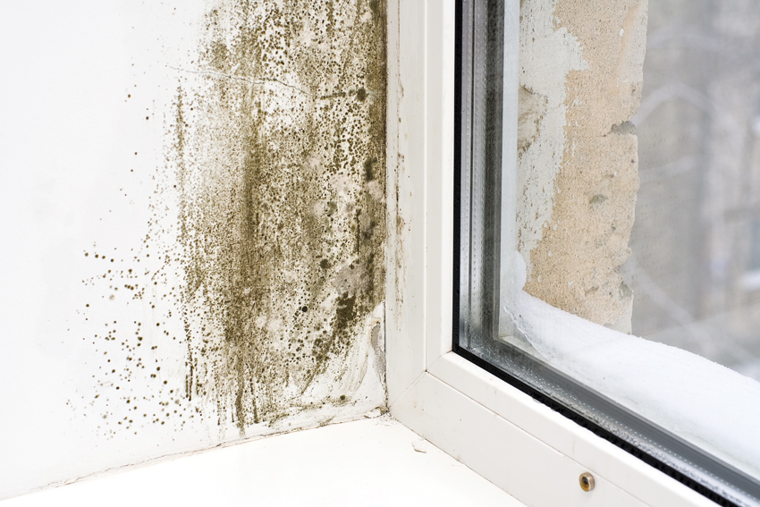
Photo courtesy of TAMLYN
Water-resistive barriers (WRBs) and drainable walls are required by code to protect exterior wall assemblies and prevent the problems of water penetration.
Outside of the IECC, there are numerous organizations that have been addressing the issues related to energy performance in buildings. The non-profit organization Architecture 2030, for example, has done an excellent job of communicating data from public sources that identify buildings in the United States as responsible for nearly half of all energy usage and 40 percent of carbon emissions. Relatedly, more than 70 percent of the electricity generated in the United States is consumed in buildings. This information has helped many people realize the significant impact that reduced energy usage in buildings can hold—almost as much as the impact from both transportation (cars, mass transit, airlines) and industry (other than construction) combined. Accordingly, many well-known voluntary programs such as the Architecture 2030 Challenge, The AIA 2030 Commitment, LEED, ENERGY STAR for Buildings, Passive House, The Living Building Challenge, and others have all emerged and evolved within the past 20 years to become an integral part of mainstream building design.
Pushed by this movement, the IECC has undergone a number of revisions and updates in this time focused on establishing the “code minimum” level of energy performance while still allowing these other voluntary programs to go beyond that level. Note that the health, safety, and welfare significance of the IECC is more than just a concern for the environment in general related to air quality and climate change. It is also based on addressing the adequacy of the supply of energy to buildings. The energy crisis of the 1970s demonstrated that real or imposed shortages of energy supply posed a significant threat to the public (think about how long is too long when experiencing a power outage). Virtually all buildings now rely on energy to operate the heating, cooling, lighting, appliances, electronics, and equipment. If that supply is compromised or interrupted, so is the safety and quality of life of the people who are in those buildings.
It is not surprising then that other relevant documents outside of the IECC have been developed almost concurrently, including the following.
ASHRAE 90.1
The American Society of Heating, Refrigeration, and Air-Conditioning Engineers (ASHRAE) has long been involved in optimizing the engineering of energy-using equipment in buildings. It has also recognized the significance that the building envelope has on the amount of energy needed to operate that equipment, both in terms of capacity and in the amount of time it needs to run. As such, ASHRAE has committees and work groups made up of members and associates to generate some recognized standards for building design. ASHRAE 90.1: Energy Standard for Buildings Except Low-Rise Residential Buildings is meant to apply to most commercial, industrial, and institutional buildings. The ICC has recognized this standard as “equivalent” to, albeit not identical to, the requirements of the IECC. Hence, it is a recognized alternative to use when showing code compliance for nonresidential buildings. While there are indeed differences between ASHRAE 90.1 and the IECC, a building designed to meet the minimum standard of either one should yield approximately the same overall energy performance.
California Title 24
In the state of California, the codes are referred to as the California Building Standards Code, which is embodied in the California Code of Regulations, Title 24. It is commonly referred to simply as Title 24 and includes 1) some adopted I-Codes as written; 2) some I-Codes with adaptations to suit California; and 3) some California-generated standards to suit particular state concerns. As such, the Title 24 codes are generally more stringent, particularly in regards to energy performance and seismic issues, than the model I-Codes alone. This means that the “code minimum” threshold for energy performance can be expected to be higher in California than elsewhere in comparable climate zones. It has also been observed that other states, particularly those in the Pacific Northwest, have begun to follow California’s lead and are starting to incorporate their own state adaptations to the model codes.
International Green Construction Code
The ICC has collaborated with a number of non-profit organizations to create a model green building code. Referred to as the International Green Construction Code (IgCC), it addresses more than just energy, including other common aspects of a green building such as site design, water usage, material selections, and indoor environmental quality. This code has primarily been adopted by localities, as opposed to statewide adoptions, and provides multiple options for achieving minimum performance levels. It works in a very similar manner to the voluntary programs (such as LEED) but codifies it so that code enforcement officials have a tool to work with similar to other codes.
Based on all of these developments, it is clear that the future direction of energy code updates and the purview of authorities having jurisdiction is to continue to seek better energy performance in buildings and reduce the emissions caused by the use of fossil fuels in the heating, cooling, and operation of buildings or generation of electricity.
Building Envelope Update
The latest published version of the IBC and IRC is 2018, which was finalized at the end of 2017. The code development process for the 2021 versions is now complete, with publication expected by January of 2021. By way of example, we can look at one significant exterior wall update to demonstrate how the codes have been revised to suit current needs and conditions.
Water-Resistive Barriers
Both the IBC and the IRC have required that exterior building walls are protected from the elements to prevent potentially damaging water penetration into the rest of the wall assembly. Commonly, particularly on stud-framed walls, this includes a cladding material (i.e., siding, metal, masonry, stucco, etc.) as the outermost first layer of defense. This is the visible material on the outside of wall assemblies and is usually chosen for a combination of design, performance, and cost reasons. Underneath, however, and usually not visible, is where the second code-required layer resides. In prior versions of the code, it was referred to as simply a “weather-resistant barrier” (WRB) with limited expectations. More recent versions of the code (i.e., 2012 and later) require a “water-resistive barrier” (WRB) defined as “a material behind an exterior wall covering that is intended to resist liquid water that has penetrated behind the exterior covering from further intruding into the exterior wall assembly.” This clearly identifies a higher expectation that it will keep water from passing into the full wall assembly.
This requirement for a WRB has been in the code for quite some time. In fact, the only stated material for a WRB is “not fewer than one layer of No. 15 asphalt felt, complying with ASTM D226 for Type 1 felt or other approved materials,” (IBC 1403.2). In this case, “approved” is a defined term in the code meaning “acceptable to the building official.” In response, most modern material manufacturers of WRBs will have their products independently tested and rated to demonstrate that they perform at least as well as, if not better than, Type 1 asphalt felt to allow them to be approved by the building official, not to mention the architect of record. Note that the minimum requirements for acceptance are specific and outlined in Acceptance Criteria for a WRB published by the ICC Evaluation Service (ICC-ES), a subsidiary of the ICC.
Source: International Code Council
The 2018 International Energy Conservation Code (IECC) reflects the latest "code minimum" standards for energy performance in buildings.
Water Drainage
In addition to the requirement for a WRB, the IBC and IRC require “…a means for draining water that enters the assembly to the exterior,” (IBC1402.2). This is most commonly achieved through the use of a WRB designed for enhanced drainage or by detailing a full rainscreen system behind the cladding. In the fullest form of this requirement, wall systems with enhanced drainage have become common. In this assembly, the cladding is expected to allow some air and water to penetrate into a space between it and the WRB where it can then safely and harmlessly drain away. This type of approach has been common in brick veneer wall construction, which relies on such a gap and weep holes at the base to create the drainable surface and water discharge. However, on other wall systems, particularly lighter-weight framed walls with siding or stucco, creating that drainage gap has also become a more common practice for enhanced water management and drying capacity of wall systems. In fact, some siding manufacturers are starting to require it.
Air Barriers
Beyond a WRB, the energy code (IECC) requires an air barrier (AB) in exterior walls. That barrier can be located in the assembly either on the exterior or the interior but needs to be continuous across all junctions, penetrations, and openings. In some cases, manufacturers may provide detailing for a product that performs as an AB or WRB alone or a combined WRB and AB system. This means that whatever product is used, sealing the edges and any seams properly and fully without undue penetrations is critical for good performance and code compliance. Some manufacturers offer full sealing systems that use a compatible adhesive, sealant, or tape. This allows the edges to be held permanently in place, usually by using a hard roller or hand applicator to press the barrier and the tape together. With enhanced detailing, this combined approach can be a cost-effective way to achieve both the moisture- and air-infiltration performance requirements for a project.
2021 Code Update
Not all wall conditions are the same when it comes to assemblies using cladding, WRBs, and ABs. In particular, reservoir cladding systems like gypsum or cement-based stucco have suffered from entrapped moisture and reduced drying capability. Notable field issues and problems have come about as a result, which have prompted a number of proposed changes to code requirements to overcome them. Specifically, the 2021 version of the ICC codes will incorporate changes for residential, multifamily, and commercial buildings that address these concerns. These changes are specifically found in the new IRC and IBC sections of the code. In particular, Section 2510 of the IBC addresses Lathing and Furring for Cement Plaster (Stucco). For residential applications, the same language may be found in the corresponding section of the IRC.
There is a major change in the language in Section 2510 to reflect differing climate conditions across the United States. Specifically, paragraph 2510.6 has been rewritten and broken into subparagraphs to address different conditions related to dry climates and moist or marine climates. The significance of this change is the recognition that some of the problems that have been caused by moisture and condensation in stucco-covered walls are directly influenced by a local climate. Similarly, it recognizes that there is the need to allow for any trapped moisture in the wall to properly escape and drain, which was not adequately addressed before. Some of the affected sections and language are highlighted as follows:
“2510.6 Water-resistive barriers. Water-resistive barriers shall be installed as required in Section 1403.2 and, where applied over wood-based sheathing, shall comply with Section 2510.6.1 or Section 2510.6.2.”
This paragraph is a shortened version of the prior 2510.6 but still refers to the requirement for the WRB (1403.2), which we discussed earlier. It then recognizes two different climate conditions that will determine code compliance when wood-based wall sheathing is used:
“2510.6.1 Dry climates. One of the following shall apply for dry (B) climate zones:
- The water-resistive barrier shall be two layers of 10-minute Grade D paper or have a water resistance equal to or greater than two layers of water-resistive barrier complying with ASTM E2556, Type I. The individual layers shall be installed independently such that each layer provides a separate continuous plane and any flashing, installed in accordance with Section 1404.4 and intended to drain to the water-resistive barrier, is directed between the layers.
- The water-resistive barrier shall be 60-minute Grade D paper or have a water resistance equal to or greater than one layer of water-resistive barrier complying with ASTM E2556, Type II. The water-resistive barrier shall be separated from the stucco by a layer of foam plastic insulating sheathing or other non-water absorbing layer.”
In this initial condition for dry climate zones, there are several things to notice. First is that the reference to climate zones actually refers to those defined in the IECC, not the IBC. Therefore, designers need to turn to Chapter 3 of the IECC and look up the state and county of the building project location to determine not only the numeric climate zone (1–8) but also the alphabetic designation (A, B, C) for dry, moist, or marine climates. The second point to notice is that the criteria for an acceptable WRB in this case is now required to be based on a specific test. Hence, in dry climates, in order for a building official to approve a product’s use as a WRB in a stucco-based wall, independent test results must be based on ASTM E2556: Standard Specification for Vapor Permeable Flexible Sheet Water-Resistive Barriers Intended for Mechanical Attachment. Depending on the test results, the material will be classified as either a Type I or Type II, which will determine whether one layer or two layers are needed per the new code language above.
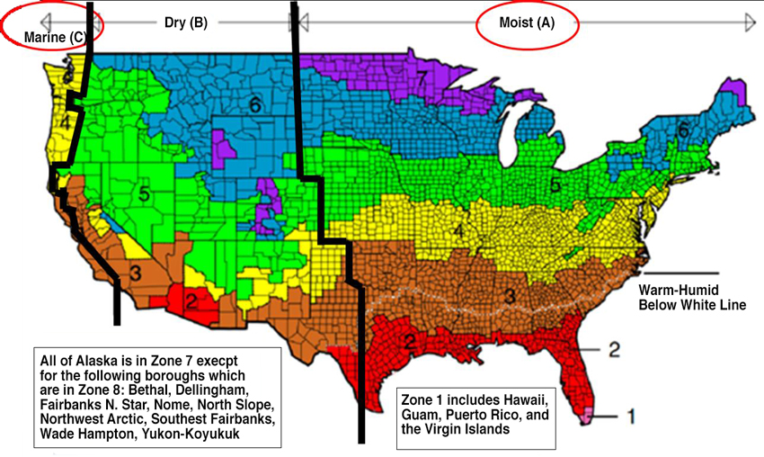
Image courtesy of TAMLYN
Climate zones are identified in the IECC not only by the eight numeric zones but also the three alphabetic zones for
A: Moist, B: Dry, and C: Marine.
The other condition cited in the 2021 IBC for WRB installation is for moist or marine climates:
“2510.6.2 Moist or marine climates. In moist (A) or marine (C) climate zones, water-resistive barrier shall comply with one of the following:
- In addition to complying with Item 1 or 2 of Section 2510.6.1, a minimum 3⁄16-inch (4.8-millimeter) space shall be added to the exterior side of the water-resistive barrier.
- In addition to complying with Item 2 of Section 2510.6.1, a space with a minimum drainage efficiency of 90 percent as measured in accordance with ASTM E2273 or Annex A2 of ASTM E2925 is added to the exterior side of the water-resistive barrier.”
Based on the climate zone map, these provisions for moist or marine climates now affect a large portion of the country. In all of those moist or marine locations, the provisions for dry climates must still be met, but there are also additional requirements. The first design option is a minimum space of 3⁄16 inch regardless of the type of WRB used. The second option allows the use of a Type II WRB provided the drainage efficiency of the system meets additional testing as listed above. These drainage provisions are intended to address water management and drying challenges behind stucco in these wetter climates, which have exhibited more issues in the field.
Tim Rogan, a principal with Houston Exterior Wall Inspection & Testing, notes, “Adding drainage requirements to stucco systems has been a long time coming. It addresses many of the issues I see in the field with moisture not getting out. Water moves in multiple dimensions within the stucco. Had this been implemented years ago, it would have saved people a lot of money.” The trend toward drainage provisions has happened independent of code adoption in many places already and is likely to become an industry standard for most cladding systems.
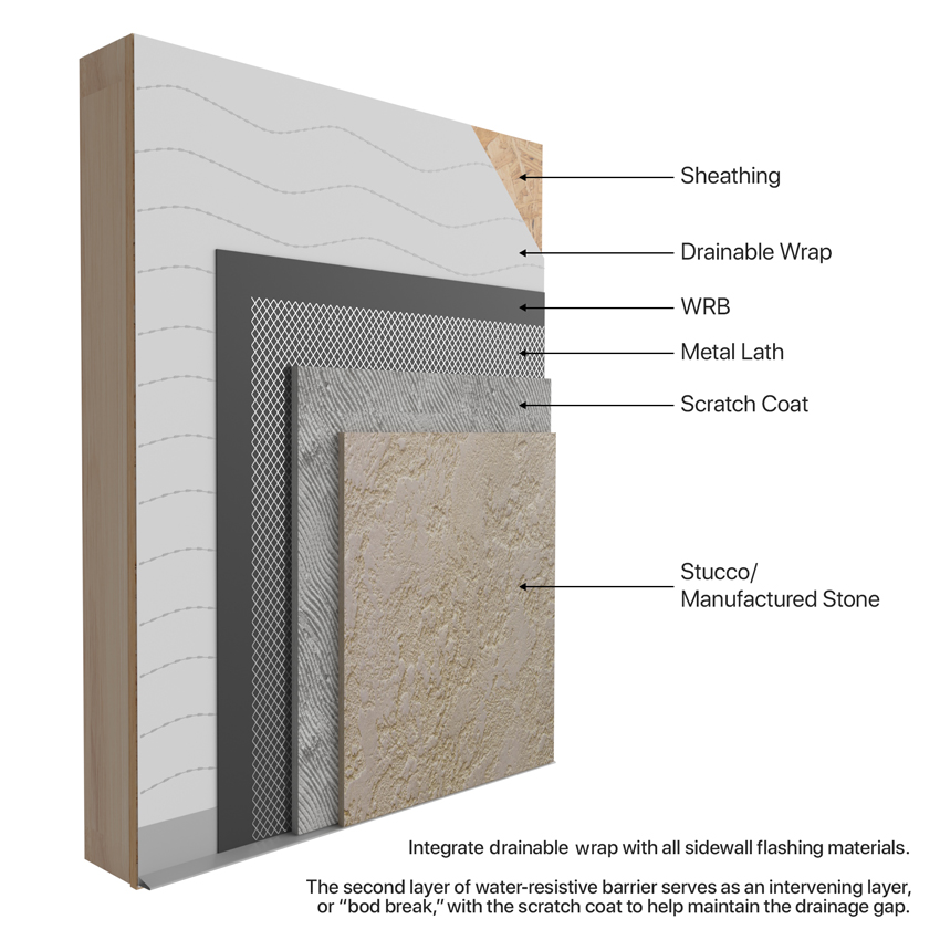
Image courtesy of TAMLYN
A code-compliant exterior wall assembly with stucco or manufactured stone now needs to meet specific requirements for a WRB and drainage.
Material Selection
In light of these new and updated code requirements, the question arises as to what type of material should be specified. In fact, the availability of drainable products and drainable systems has existed for many years since they enhance the water management and drying performance of other absorptive cladding systems as well. One approach is to use a Type II high-performance, non-woven building wrap made from a synthetic sheeting material. The advantages of a modern synthetic wrap product over traditional products (such as asphalt felt) include a WRB that is more durable and more easily sealed along the seams to create a continuous barrier over a variety of materials or different configurations.
A significant innovation in such high-performance building wraps has been the addition of integral spacers to very effectively create a manufactured drainage gap between the cladding and the wrap. The conventional means to create a gap in a framed wall system is to use furring channels or wood strips. This works, of course, but requires more labor, time, and cost to install the furring and often special considerations for adequate ventilation behind the cladding. The alternative that has become recognized as a best-practice solution is to use a drainable building wrap that provides its own integrated method of drainage that meets the drainage efficiency requirements of the code.
Specifically, at least one manufacturer creates this gap by bonding noncompressible spacers onto a high-performance WRB building wrap. The depth of the resulting drainage cavity can be specified to meet the new code requirements for reservoir cladding products, including stucco and thin stone. In essence, drainable building wrap acts as a drainable system in miniature, without the added labor or cost. To qualify, these products must be tested for drainage efficiency per ASTM E 2273. Research shows that a minimum space of 1 millimeter can provide the necessary drainage efficiency behind a cladding. To ensure the drainage gap is consistent, noncompressible designs are preferred. Further, it will work with other types of cladding systems too, particularly those that can absorb moisture, such as wood or fiber cement siding. The economical beauty of it is that the cladding can be applied directly over this drainable building wrap, eliminating the labor step of installing the spacers as a separate component. Some drainable building wraps have also been tested to qualify as an AB. This means it can also double as a continuous exterior AB, meeting the code requirements for both WRB and AB in a single layer. In addition to a drainable building wrap, manufacturers are developing novel products to achieve larger physical drainage gaps (¼1⁄4–3⁄8 inch) that perform like a full rainscreen system in a more cost-effective manner.
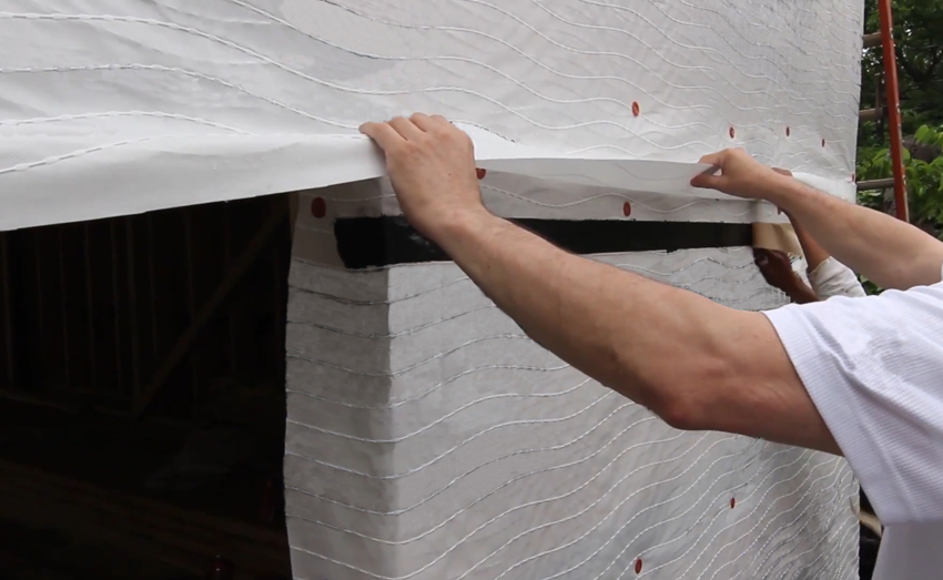
Photo courtesy of TAMLYN
High-performance building wrap with AB and WRB capabilities along with a drainable surface also need to be easily sealed along edges and around openings.
Equally important are the details of how the drainable building wrap deals with openings in the wall, such as doors and windows. Being able to flash and seal the wrap properly with window and door flashing materials will assure that water draining down the face of a drainable WRB will flow away properly and not enter behind other building elements into the wall. One simple but key element of this is to ensure all layers of the system are installed in a shingle fashion to ensure positive drainage is achieved. Taping seams and integrating with flashing materials will help the continuity of the AB in the overall system.
The use of drainable WRB systems has been common for many years and growing in popularity. The latest code changes are likely to only accelerate their use and become the standard. The experience of Greg Roggenkamp of Left Frame Design Build sums it up well: “Drainable WRBs first caught my attention due to the noncompressible drainage gap. I was amazed at how fast it went up. Very thick fabric as well. I now use it on all my projects.”
Glazing in Buildings
A significant design feature of most commercial buildings is the glass and glazing that is incorporated into a building facade. There are many variables related to their design, such as the type, size, shape, color, and configuration of the glazing, which often receive plenty of attention. There are also many variables that affect the performance and energy code compliance of the glazing system, including the percentage of glazed to opaque wall areas, the number of layers of glass, the type of glass used, glass treatments or coatings, the framing system that holds the glass, and even the type of spacers between double- or triple-paned products. It is important to recognize that all of these variables are essentially different components of a glazing system that can be controlled and specified to suit specific project conditions, climate zones, and code requirements. It is not about any one item alone (i.e., the framing system or the glass) but rather the entire makeup of all of them.
One very objective way to assess glass and glazing systems is to use the ratings developed by the National Fenestration Rating Council (NFRC). A commonly cited rating is NFRC 100, which is a set of procedures and guidelines for determining the U-factors of all types of windows and doors. This is the fundamental rating that many people look for in regard to demonstrating thermal energy performance both for influencing the building design and for demonstrating compliance with the IECC. Note that this standard looks at all of the components of a glazing product or system (i.e., window, curtain wall, entrance, storefront, etc.) and shows an overall U-factor for the product, not just the glass. This allows design professionals to make comparisons and decisions based on the total product, not just the glass used.
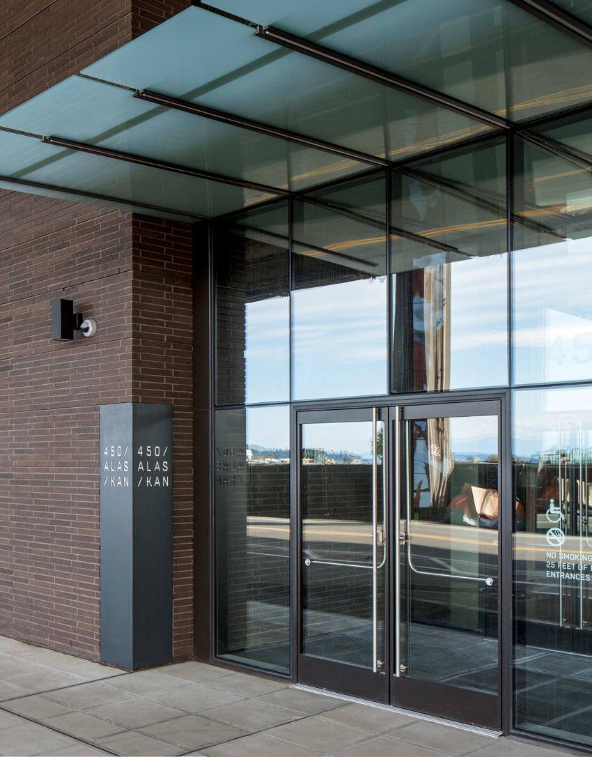
Photo courtesy of NBBJ
Glazed facades and entrances can be evaluated on performance based on testing reported by the National Fenestration Rating Council (NFRC) and others.
A similar rating is NFRC 200, which is used to determine the solar heat gain coefficient (SHGC) and visible transmittance (VT) of glazing in windows and doors. The SHGC is useful for determining how much heat is contributed from the sun through the glass. It is regulated by the IECC and has particular significance in warm climates. The VT is helpful in determining the effectiveness of daylighting and views in a space. Both of these NFRC ratings are essentially technical documents intended for use by testing labs and other window and door professionals. Hence, when window and door companies indicate that their products are tested or certified to NFRC 100 and 200, it simply means that they have had simulations and/or physical testing performed on their products in accordance with the guidelines published in NFRC 100 and 200.
The aspects that manufacturers control that directly influence the results of the NFRC ratings are many and varied. The glass can be standard double glazed or higher-performing triple glazed. The spaces between the glass panes can be separated by standard aluminum spacers or high-performance “warm-edge” spacers. The air in those spaces can be replaced with an inert gas such as argon. The glass itself can be treated with coatings to improve thermal emissivity (i.e., low-e) or change the SHGC—either of which may directly affect the VT of the glass and its coloration. The frames of the glazing systems used in commercial buildings are typically made out of aluminum, which is great at conducting heat and not good at restricting it. Hence, manufacturers incorporate one or more thermal breaks in the aluminum framing such that inner and outer aluminum members are held together with materials that conduct less heat but maintain appropriate strength.
All of these performance details can be specified in a project, along with the preferred appearance characteristics to achieve the desired outcomes. However, working with an experienced glazing systems manufacturer can help ensure that particular combinations of characteristics is indeed possible and available. It can also help determine the relative cost impact of different selections. If code compliance is a concern, it may also be able to help in that regard by offering systems that have been accepted in similar climate zones for similar projects. If there is any doubt, however, on which version of the IECC is in effect or what the code requirements for glazing are, the local authority having jurisdiction should be consulted.
Glass Entrance Systems
A great example of a glazing system that is widely used and needs to be fully code-compliant are glass entrance systems. These are often sought after as a visual focal point because they create an inviting sense of transparency leading into the building, while offering contemporary, elegant all-glass aesthetics. Hence, many commercial, institutional, and industrial buildings incorporate glass entrance systems on the main floor. While these are fairly common and may look similar, there are real differences in the way these types of entrance products perform. In the case of energy code compliance, attention needs to be placed on the specification of all of the component parts and materials of these glazed entrance systems.
Achieving the desired level of performance is based fundamentally on three things: 1) the structural and material integrity of the aluminum frame and glass; 2) the insulating value of the system; and 3) the ability to prevent air and water infiltration through the system. Fortunately, there are products available that address all three of these criteria and manage to do so with great aesthetic qualities. For example, there are ultra-narrow stile entrance systems available that provide an elegant, all-glass appearance, while still delivering exceptional thermal performance normally found in full-frame doors. Excellent thermal performance translates to U-factors as low as 0.33 to help control heat transfer. This is achieved in part by allowing insulating glass units (IGUs) to be used that are up to 1-inch thick. In addition, such entrance systems can demonstrate that they meet or exceed the air-infiltration requirements of the IECC and ASHRAE 90.1, both of which contain mandatory provisions on this topic.
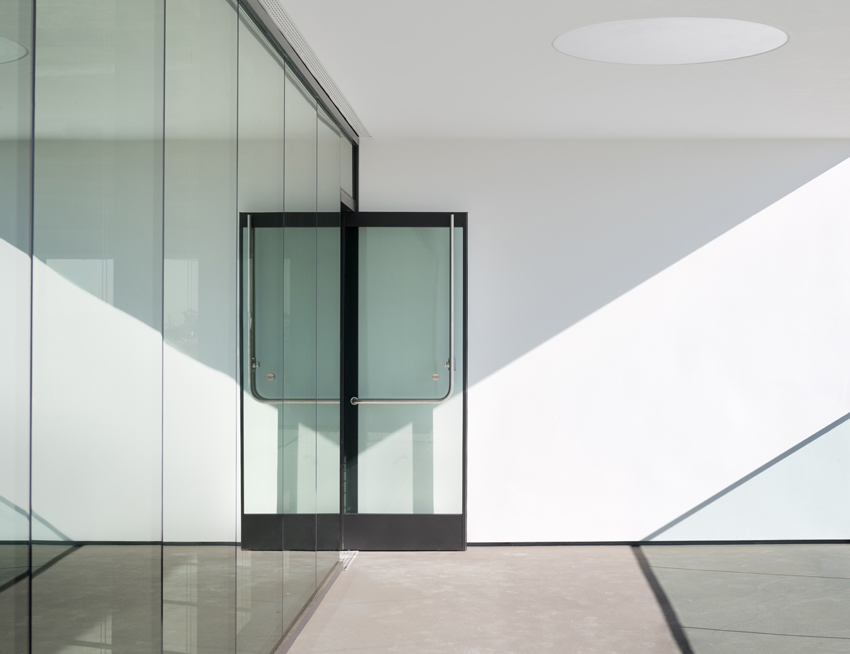
Photo: Geoff Captain
Glazed entrance systems are available that are fully code compliant while also offering very elegant, clean visual appearances with narrow stiles and minimal hardware.
When it comes to the hardware used for door pulls and panic devices, there are options in this regard too. Commonly, such door hardware is attached directly to the frame. However, some manufacturers have developed a means to secure door-pull hardware directly onto 1-inch insulating glass panels using unique through-glass fittings. Styles include sleek tubular panic devices that yield an attractive floating-on-air appearance because the handles do not have to be attached to door stiles. This provides an added aesthetic and functional benefit without compromising the performance of the doors. This means that architects do not have to sacrifice aesthetics in place of thermal performance. By specifying an all-glass entrance system with the appropriate insulating glass, the glass composition of the surrounding framing system can match the entrance system, thus avoiding high variations in performance and looks. Maria A. Gomez, a principal with GFF Architects, sums it up this way: “The ultra-narrow stile entrance products we have specified solve the requirement for thermal performance and weather protection while maintaining an upscale look.”
Conclusion
Building and energy codes are developed and updated in a very open, transparent, and inclusive process following a three-year cycle. Other standards and programs are recognized by the codes, particularly the IECC, as alternative ways to show code compliance. Updates specific to the 2021 I-Codes address issues related to WRBs in walls that may hold water, such as stucco. The design and specification of glazed entry systems require attention to detail of all of the components to understand the total performance and code compliance. Architects who recognize the interrelatedness of the code development process and day-to-day design and construction work will achieve better understanding of effective building performance and code-compliant strategies.
Peter J. Arsenault, FAIA, NCARB, LEED AP, is a nationally known architect, consultant, continuing education presenter, and prolific author advancing building performance through better design. www.pjaarch.com, www.linkedin.com/in/pjaarch