This CE Center article is no longer eligible for receiving credits.
One of the major focuses of green construction is delivering energy-efficient buildings. A mastery of HVAC design is, therefore, critical for design professionals engaged in the growing demand for LEED®-certified structures.
Most buildings have some type of heating, ventilation and air conditioning system. Yet, until relatively recently in the U.S., HVAC systems were aptly characterized as "horse and buggy" technology, having changed little over past decades. Now available on the market are state-of-the-art solutions employed and proven elsewhere in the world. One such new system that was developed in Japan, and widely used in Asia, Europe and South America, is Variable Refrigerant Flow (VRF) zoning, an energy-efficient method of providing precise zoned comfort control to indoor environments. At present, VRF is only about one percent of the HVAC market dollar volume, but its growth potential is staggering when one considers the increasing volumes in the past five years alone of the education, government/military, healthcare, lodging, multifamily and office sectors and their growing requirements for green construction. Other potential markets include churches and public buildings such as museums, civic centers and performing arts facilities.
HVAC OVERVIEW
Generating approximately $15 billion a year, the HVAC industry has been the subject of numerous analyses on the significant role it plays in U.S. energy consumption. According to the U.S. Department of Energy's Buildings Data Book, 22 percent of the nation's energy is consumed by HVAC in commercial buildings and 18 percent by the residential sector (transportation consumes 28 percent).
 |
|
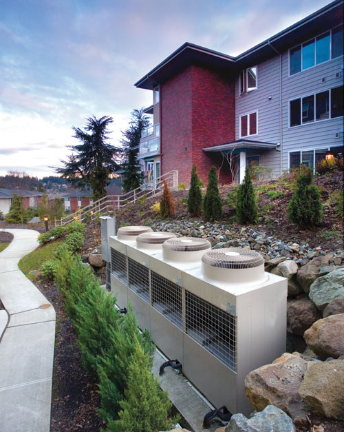
Photo courtesy of Mitsubishi Electric |
The most common types of HVAC equipment are unitary air conditioners and heat pumps. "Unitary" refers to the fact that all of the components necessary to heat, cool, dehumidify, filter and move air are included in one or more factory-made assemblies. "Heat pumps" refer to an air-conditioning system that is capable of reversing the direction of refrigerant flow to provide either cooling or heating to the indoor space.
Light commercial and residential HVAC types include packaged terminal air-conditioning units (PTACs), unitary units, window units, wall-mounted units, radiant heaters and ductless systems.
For large commercial and industrial applications, HVAC options fall under one of three categories:
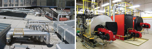
Packaged Systems: The HVAC system is contained in one unit. This type of HVAC system can include traditional boilers, chillers, water-source heat pumps and multi-zone rooftop units–basically any system that is based on water or direct expansion (DX). Typically, conditioned air is ducted from the system to the indoor space through ducts.
Split Systems: The system has two parts, usually an indoor air-handling unit and outdoor unit housing the compressor. Again, the components of this system can include boilers, chillers and water source heat pumps, etc. A split ductless system is comprised of a remote outdoor condensing unit connected by refrigerant pipes to a matching, non-ducted indoor air handler. Special cases for introducing fresh air may call for limited ducting to the air handler from outside.
VRF Systems: A flexible version of both of the more traditional options, with the key difference being that VRF reacts to changes in cooling and heating requirements by varying the flow of refrigerant to individual zones as opposed to moving cooled or heated air through ductwork to those spaces.
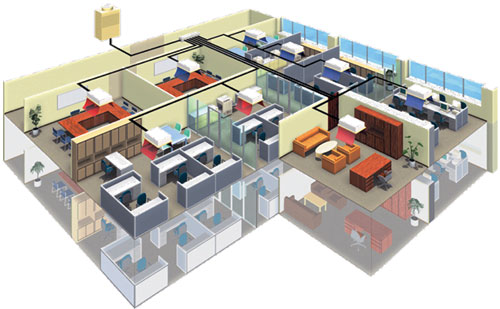 |
VRF systems include a central variable capacity outdoor unit connected to multiple variable capacity indoor units.
Photo courtesy of Mitsubishi Electric |
What is Variable Refrigerant Flow?
Variable Refrigerant Flow (VRF) technology is an energy-efficient method of providing precise comfort control to indoor environments. Varying the refrigerant flow to each zone or indoor unit servicing that zone allows the system to constantly monitor and control the amount of cooling or heating that is being delivered through each unit. This allows the temperature of that area to be more precisely controlled.
By utilizing a branch circuit controller, the system can simultaneously cool some zones while heating other areas, thus providing the ultimate in zoned comfort. (Zones are single or multiple room spaces that are conditioned to a set temperature and are operated independently from other rooms within the same structure.)
Inverter-driven compressor
VRF technology is accomplished through the use of an inverter-driven (variable speed) compressor housed in the outdoor unit, which responds to indoor temperature changes. Because an inverter compressor can vary its motor rotation speed and capacity and the indoor units can vary their capacity, the system delivers the capacity to precisely meet the load in each zone. Power consumption is therefore reduced because the system operates only at the levels needed to maintain a constant and comfortable indoor environment.
 |
Exposed VRF system for a café demonstrates flexibility of placement and installation.
Photo courtesy of Mitsubishi Electric |
Inverter compressor technology is highly responsive and efficient. The technology allows for compact, quiet units; flexibility of placement; and gives architects and owners more design freedom with integrated, simple to use controls.
A typical system is made up of a central variable capacity outdoor unit connected to as many as 50 variable capacity indoor units.
Inverter technology can be compared to an automobile's cruise control. Just as the driver sets the velocity in a car, the facility manager or building occupant determines the temperature setpoint. The cruise control works to maintain the car's velocity as it goes up and down hills and around curves. Similarly, inverter compressors ramp up to achieve the desired setpoint. Once the setpoint has been achieved, the indoor units operate with long runs at a low level in order to maintain the temperature setpoint. Conversely, traditional HVAC systems use more energy to maintain the temperature setpoint because of short cycling or from the need to turn the compressor fully off and on. This use demands the maximum energy output each time the system starts.
Energy can be lost in other ways in traditional ducted systems. Moving air throughout a building requires long runs of ductwork and the use of larger fan motors to move the air. This wastes a significant amount of energy when compared with a VRF system, which moves refrigerant to the indoor unit–the unit is either inside or in close proximity to the space–and then uses a small fan motor to move air.
 |
Inverter-driven compressors maintain room temperatures at a steady setpoint.
Chart courtesy of Mitsubishi Electric |
Part-Load Operations
As of January 1, 2010, the Air Conditioning, Heating and Refrigeration Institute (AHRI) has established a new procedure yielding an Integrated Energy Efficiency Ratio (IEER) rating. This is a great improvement over the unitary-only IPLV (Integrated Part Load Value) method because it covers all units even if they are single stage. To obtain IEER ratings, the systems are tested at four different capacity levels and outdoor temperature conditions to provide a very accurate part-load measure. IEER should be the gold standard for part-load systems in the near future. Those manufacturers of VRF systems with inverter technology are well positioned to achieve high IEER ratings. |
VRF Systems are Energy Efficient
Energy modeling software has been used to compare inverter-driven VRF split-systems with other types of systems, applying the design conditions for several major U.S. cities. VRF systems were consistently 25 percent or more efficient than traditional systems at start-up. There are several factors that contribute to energy efficiency. These include low capacity operation, ramp up speed, zoned capabilities, heat recovery technology and heat pump technology.
Operates at low capacity
Low capacity inverter-driven compressors permit capacity operation as low as 4 percent. Most fixed-speed compressors in traditional HVAC systems are either off or on, wasting energy when partial-load conditions prevail. Even a traditional system with two or three stages, doesn't compare to the full-range variable capacity of the inverter-driven system that fully supports part-load operation. (See sidebar Part-Load Operations above.)
 |
Simultaneous cooling and heating (heat recovery) system includes an outdoor unit, a branch controller and indoor units.
Image courtesy of Mitsubishi Electric |
Ramps up quickly
Inverter compressors ramp up quickly, providing the energy necessary to achieve the cooling or heating demand of the zone. Working in tandem with system controls and sensors, the inverter compressor varies its speed to maintain the desired comfort level. Thus, the system only uses the amount of energy required to satisfy the cooling and heating requirements of each zone.
Zoning capabilities
Inverter-driven VRF systems save energy, while providing a high degree of comfort through their zoning capabilities. Zones or rooms can be designed to exact needs, taking into account occupancy, solar gain parameters, and diversity of usage.
Intelligent indoor units have sensors to measure room air temperature at the return. If the design requires it, air temperature can be measured at a remote controller. The ability to choose the measurement location allows for better air temperature management, maintaining the set point within one degree Fahrenheit. Some VRF system indoor units feature a special sensor accessory, which senses and compares air and floor temperatures, and then adjusts the unit output as needed to optimize the comfort within the space. All indoor units feature linear expansion valves to ensure the precise amount of refrigerant and capacity are delivered to the zone.
Typical VRF systems with multiple indoor (air-handling) evaporator units connected to an outdoor compressor unit can deliver just the right amount of refrigerant to precisely meet each zone's load. Indoor units can be controlled to operate only in those occupied areas that need conditioning; indoor units in vacant areas can be turned off. By conditioning only the occupied areas, heating or cooling capacity is not wasted.
Since conventional HVAC systems are sized depending on the cooling and heating peak loads of the building, the combined capacity of the indoor units can match, exceed, or be lower than the capacity of the connected outdoor unit. Inverter-driven VRF systems, on the other hand, can be designed and sized on a zone-by-zone basis to adjust for a building's solar gain and the changing seasons. Depending on the system selected, typically up to 50 indoor units can be connected to each outdoor unit, producing a total applied capacity of up to 150 percent of the outdoor unit's rated capacity.
Heat recovery system
Certain VRF systems have the ability to simultaneously operate in cooling and heating modes–using the building's own environment to save energy. These systems, also called heat recovery systems, include an outdoor unit, indoor units and a branch circuit (BC) controller to control the refrigerant being delivered to separate indoor units requiring cooling and heating. The BC controller facilitates removal of wasted energy from one zone, and applies it to a different zone. For example, if an indoor unit in one room is calling for cooling and an indoor unit in another room is calling for heating, the BC controller can take the heat removed from the room that is being cooled and use it to warm the room that needs heat. This reduces the cooling or heating requirements put on the compressor, saving electricity. Heat recovery systems are offered with a connected capacity of up to 150 percent of the outdoor unit's rated capacity. Typically, these systems are available up to 24 tons of capacity.
VRF manufacturers either use 2-pipe or 3-pipe technology to create a simultaneous cooling and heating system. A 2-pipe system uses a single branch controller box which distributes refrigerant to individual indoor units which operate independently. A 3-pipe system requires a branch selector box at each zone to provide independent operation. The other large difference lies in the amount of piping connections required by each type of system. As shown in the illustrations, the number of piping connections is much less for a 2-pipe system than a 3-pipe system. Since connections can be directly correlated to installation time, connections are a good estimation of installation cost.
VRF heat pump technology
A VRF heat pump system can operate in either a cooling or heating mode. They include an outdoor or water source unit, headers or branch joints, indoor units and a control system. By taking advantage of the diversity in a building, heat pump systems are capable of operating with a connected capacity of 130-plus percent. Heat pump systems are available up to 30 tons of capacity.
 |
A 2-pipe system uses a single branch controller.
Images courtesy of Mitsubishi Electric |
 |
| A 3-pipe system requires a branch connector box for each zone. |
VRF System Advantages
In addition to energy efficiency, VRF systems have many significant advantages. These include integrated controls, quiet operation, design and installation flexibility, compact equipment, lowered lifecycle cost and reduced maintenance costs.
Integrated controls
VRF systems utilize an integrated controls network that links the entire system. The integrated controls network allows all parts of the VRF system to communicate, constantly maximizing efficiency and dialing in the capacity of the system. It also saves data for the purposes of verifyng and measuring long term performance–a necessary feature for obtaining LEED® credit.
A facility manager is able to remotely reset the building's temperature appropriately. If the building is operating in cooling and the outside temperature drops unexpectedly, the facility manager, with a couple of clicks from a remote location, is able to bump up the temperature setpoint, thus saving valuable time and energy.
The controls network can be tied into a standard building management system (BMS). It also may be customized with Internet access. The controls network offers tenant billing which, when combined with watt meters on the exterior, gives the building owner the ability to bill each tenant individually.
Quiet operation
Manufacturers have designed VRF air conditioning systems to operate quietly. Moreover, operating sound levels are greatly reduced because the speed of both the inverter compressor and the condenser fan ramps up and down smoothly when the system's capacity varies. The compressor is surrounded by sound insulation while being housed in its own compartment. These features are especially relevant for libraries, places of worship, lecture halls, classrooms, hospitality spaces and theaters.
 |
Heat pumps can both cool and heat.
Image courtesy of Mitsubishi Electric |
Sound pressure levels on one indoor evaporator unit range from 19 dB(A) at low speed (decibel A-weighting takes into consideration the human ear's sensitivity to certain frequencies) to 49 dB(A) at high speed; on another indoor unit, sound pressure levels range from 22 dB(A) at low speed to 47 dB(A) at high speed. Standard indoor equipment sound levels are generally between 45 and 55 dB(A). The sound of indoor units is generally on a par with a recording studio or library.
Outdoor compressor units are also quiet, operating from 50 dB(A) for one small capacity model to about 65 dB(A) for a larger modular unit–no louder than a typical conversation. A typical commercial application of a VRF system has sound levels as low as 61 dB(A). Special care is taken in the design of the outdoor units so that sound is reduced at the source. Specially designed blades and multi-speed motors also reduce system operation sound. The low sound levels allow these outdoor compressor units to be installed near windows, on balconies or near rooftop amenities, giving back usable space and minimizing disruption to the environment.
The great variety of indoor unit styles gives design professionals greater flexibility in deciding on the style, from wall mounted to ceiling concealed, to further minimize any unwanted sound.
Design flexibility
VRF systems offer design, installation and location flexibility.
 |
Plenum space can be reduced by running smaller pipes for VRF systems.
Image courtesy of Mitsubishi Electric |
Space saving. Compact inverter compressors and smaller VRF system components, can be installed in smaller spaces both indoors and out, thus freeing up spaces for other uses.
In many buildings, the plenum space requirements are dictated by the mechanical equipment. Since copper refrigerant piping is smaller and lighter than ductwork or steel water pipes used in conventional systems, plenum space can be given back in the form of higher ceiling heights. If enough space is saved on enough floors throughout the building, space can be given back in the form of an additional floor, without the need to increase the overall building height. Smaller sized piping and ductwork are also advantageous when specified for existing buildings.
VRF systems also need less piping and duct space. Compared with chilled water systems VRF systems require smaller amounts of piping to connect the outdoor unit to the indoor units (see figure comparing water piping and ductwork required for VRF and chilled water systems).
With its compact-sized components and small-sized copper piping VRF systems are particularly suitable for adaptive reuse and historic renovation.
Another way that VRF gives back space is by reducing the need for mechanical rooms. Chilled water systems require mechanical rooms to house pumps, chillers, heat exchangers and other equipment that are needed for the chilled water system to function properly. All these systems require space and are additional weight on the structure. VRF reduces the need for all this supporting equipment and gives it back to the owner.
With mechanical equipment taking up less space, there can be more usable interior space. Moreover, more consideration can be given for providing spaces for green roofs, thus further reducing the footprint's impact on the project
Location and installation flexibility. The modular nature of VRF allows considerable flexibility regarding the location of the outdoor unit. It can be mounted either above or below the indoor units within the limitations of the piping lengths, which, depending upon the manufacturer can measure up to 2,624 feet and 3,280 one way. Many VRF systems use T-branches and headers, which add to placement flexibility. Installation generally includes simple two-pipe systems with easy, non-polar, two-wire control connections. This translates into less labor and fewer materials as well as quicker and easier installation.
Total installation costs for VRF may also be smaller, depending on the size of the system–fewer components mean less time spent on installation, and lengths of small-diameter refrigerant piping are easier to install than lengths of ductwork.
Outdoor units (heat recovery, heat pumps) offer vertical air discharge that allows units to be installed side-by-side in a single area, saving space and resources.
 |
Comparison of pipe or duct required to deliver 20 tons of cooling for VRF versus chilled water systems. VRF uses (2) 1-1/8-in. with 1/2-in. insulation, a total of 2-1/8-in. diameter per pipe. Chilled water uses (2) 3-in. with 1-1/2-in. insulation for a total of 6-in. diameter per duct. Ductwork can be up to 30-in. round.
Image courtesy of Mitsubishi Electric |
Ventilation
In hot and humid climates or in situations where there are high occupancy zones, a separate ventilation system may be required. Some major manufacturers offer outside air processing and indoor units that can mix in ventilation air.
Lighter in weight
VRF systems are lighter than chilled water systems. They also cost less to transport. Based on standard manufacturer data, the average equipment weight per ton for a VRF outdoor unit is 70 lbs per ton; the average equipment weight per ton for water-cooled chiller is 101 lbs/ton. The VRF system, thus, shows a 31 percent equipment weight reduction when compared with a water cooled chiller. This can effect a significant reduction in additional structural cost.
Moreover, due to the modular nature of VRF, the load can be distributed across the existing structure, or even avoided by mounting on the ground. Rather than having to find space and structure for a large chilled water system or rooftop unit, the VRF system can fit into smaller spaces and be hidden more easily. This reduces point loads on the building and the possible need for additional structural support.
Lower life cycle costs
Depending on the design and needs of a building, VRF and split systems can have fewer components than other HVAC systems, reducing initial equipment costs. Installation costs for VRF and split systems would therefore be smaller–fewer components mean less time spent on installation, and lengths of small-diameter refrigerant piping are easier to install than lengths of ductwork.
According to manufacturers, VRF and split system indoor and outdoor units are robust, have a life expectancy of 15 to 20 years, and require significantly less maintenance than other systems. Many other systems require retro-commissioning and constant maintenance to preserve their installed efficiency, but VRF technology has the logic built in. VRF system performance is constantly being modified to maximize performance and comfort during its normal operations; changing or cleaning the filters is the only required periodic maintenance.
Specification Choices
Since VRF modular technology presents design professionals with multiple possibilities, some manufacturers are offering training and support. "In the past two years alone about 20,000 people have gone through our training on ductless and VRF systems," reports Meredith Emmerich, Mitsubishi Electric Cooling & Heating's senior director of application support.
Specifiers also have multiple options. All indoor units are available in a variety of styles. Ductless wall-mounted, ceiling-suspended and floor-mounted units are options for spaces where ceilings are exposed. These units provide efficient comfort to spaces without detracting from the existing architecture with large pipes or ductwork running along the ceiling. The floor-mounted unit also has the capability of being installed in a millwork enclosure allowing the unit to further blend in with the architectural design.
 |
Traditional systems require roof tops and mechanical rooms for equipment and ductwork. VRF systems leave space for green roofs and more usable building square footage.
Images courtesy of Mitsubishi Electric |
Options for ducted units include vertical units and low profile horizontal medium and high static units.
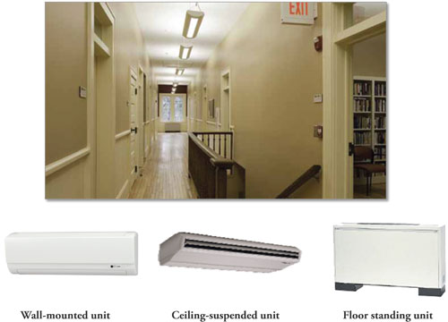 |
Examples of ductless indoor units.
Images courtesy of Mitsubishi Electric |
Compact ceiling-recessed cassette units may be specified for lay-in ceilings. In four-way units the auto fan speed feature automatically adjusts the fan speed based on the difference in set temperature and room temperature. A one-way or single direction airflow cassette may be used for combating excessive heat from a window, or in a small office area.
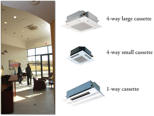 |
Compact ceiling-recessed cassette units for lay-in ceilings help reduce plenum space requirements.
Images courtesy of Mitsubishi Electric |
Ceiling cassettes, ceiling-suspended, horizontal- and vertical-ducted units and floor-mounted units may all have the capability of accepting ventilation air. The cassette and space mounted models provide a knockout to introduce ventilation air. The ducted models can mix ventilation air into the return air system. The ability to accept ventilation air ensures that the VRF system will provide a high level of indoor air quality as well as comfort control.
As with any new technology, a lack of familiarity and history of documentation will always raise questions. In response, the American Society of Heating, Refrigerating and Air-Conditioning Engineers (ASHRAE) has assembled a group to study VRF and develop documentation. In its 2008 handbook, the association included a description of VRF systems and expects to publish a separate chapter on VRF in 2012.
VRF Sustainability and LEED®
VRF system can contribute a great deal to meeting LEED requirements in the Energy & Atmosphere (EA) category (21 points) and Indoor Environmental Quality (IEQ) category (3 points.)
EA Credit 1: Optimize Energy Performance
1–19 Points
Intent
To achieve increasing levels of energy performance beyond the prerequisite standard to reduce environmental and economic impacts associated with excessive energy use.
OPTION 1. Whole Building Energy Simulation. Demonstrate a percentage improvement in the proposed building performance rating compared with the baseline building performance rating.
The required verification can be accomplished by using modeling software that incorporates VRF systems. Through a partnership with EnergySoft, selected VRF manufacturers helped integrate VRF functions into an existing software tool called EnergyProTM, which can be used to model VRF systems. EnergyPro energy modeling results are acceptable for use in LEED documentation (EA Credit 1.) EnergyPro is available to designers and engineers at a discounted price through many VRF manufacturers. To date, EnergyPro is the only software with the capability to model VRF systems. It uses DOE2.1e (building energy use and cost analysis software developed mostly under funding from the U.S. Department of Energy) to model and compare VRF to other HVAC systems. (See chart of an example of EnergyPro modeling of VRF cost savings in a single-story school where both the EA prerequisite and the minimum percentage of savings to achieve points were met.)
EA Credit 5: Measurement and Verification
3 Points
Intent
To provide for the ongoing accountability of building energy consumption over time.
OPTION 1.
Develop and implement a measurement and verification (M&V) plan
Measurement and verification can be met by the use of integrated maintenance software offered by VRF manufacturers. In addition to monitoring and collecting VRF system data, the software saves data for the purposes of trending and system analysis.
IEQ Credit 1: Outdoor Air Delivery Monitoring
1 Point
Intent
To provide capacity for ventilation system monitoring to help promote occupant comfort and well-being.
To obtain this credit, an energy recovery ventilator (ERV) can be utilized with CO2 sensors and integrated into the VRF controls network. When an ERV system is included, some VRF systems can earn points toward outdoor air delivery monitoring, increased ventilation and indoor air quality management during construction, before occupancy. VRF indoor units can be designed to avoid cross-contaminating zone air, adding to indoor chemical and pollutant source control.
IE Q Credit 6.2: Controllability of Systems–Thermal Comfort
1 Point
Intent
To provide a high level of thermal comfort system control by individual occupants or groups in multi-occupant spaces (e.g., classrooms or conference areas) and promote their productivity, comfort and well-being.
The zoning ability with VRF systems allows occupant control via wall-mounted remote controllers. Occupants can control airflow direction, speed and temperature.
IE Q Credit 7.1: Thermal Comfort–Design
1 Point
Intent
To provide a comfortable thermal environment that promotes occupant productivity and well-being.
Requirements
Design heating, ventilating and air conditioning (HVAC) systems and the building envelope to meet the requirements of ASHRAE Standard 55-2004, Thermal Comfort Conditions for Human Occupancy.
Again, VRF systems with its integrated controls, comparative modeling software and integrated maintenance software can provide and document appropriate thermal comfort.
Maintenance
In contrast to many other systems which require retro-commissioning and constant maintenance to preserve their installed efficiency, VRF technology has all the logic built in and is continuously modified during daily operations as it maximizes performance and comfort. Normal maintenance consists of changing or cleaning filters and cleaning coils. System tests are available to check wiring, sensor and the refrigerant levels. Many systems allow an indoor unit to be serviced while other indoor units within the same piping system are still in operation. VRF technology also allows for lower maintenance costs than water-cooled chillers since water treatment issues are avoided.
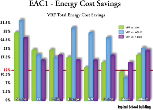 |
EnergyPro comparison of VRF cost savings in a single-story school. The building was set up to be code compliant; the only factor changed was the HVAC system. The VRF system was compared to a 4-pipe fan coil unit system, a water source heat pump system (WSHP), and a packaged variable air volume system (VAV) with hot water reheat. In many cases a VRF system met or exceeded the 10 percent improvement required by EA Prerequisite 2 and also met or exceeded the 12 percent required to achieve points under EAC1.
Image courtesy of Mitsubishi Electric |
Summary of Features of VRF Inverter Compressor Technology
- More energy efficient compared with other HVAC systems
- Sizing flexibility with variable capacity
- Offers design, location and installation flexibility
- Space-saving compact units
- Reduced piping and ductwork
- Quiet operation
- Zoning capabilities- Lower total installed costs compared with other HVAC systems
- Lower life cycle costs
- Costs of installing an extensive system can be recovered within five years
- Enables long runtimes without continually re-cycling
- Built-in logic allows continuous monitoring and controlling
- Accelerated cooling and heating performance means that the temperature setpoint is reached faster than with traditional HVAC systems
- Integrated controls allow monitoring and control from remote location
- Low rotation speed at start-up keeps power current minimal, thus eliminating power spikes that can affect appliances
- No ON/OFF as in conventional systems |
Conclusion
With their design and installation flexibility, energy saving features and delivery of comfort to occupants, VRF systems are a viable alternative to traditional HVAC systems. Since 22 percent of the country's energy is consumed by HVAC in commercial buildings, a system that reduces energy usage should go a long way towards increasing sustainability–and earning LEED credits. VRF technology offers an environmental and cost effective option for design professionals in the United States.
 |
Ductless & VRF solutions from Mitsubishi Electric Cooling & Heating, America's #1 selling brand of ductless, are compact and quiet. And with no ductwork, they minimize impact on your design while providing extremely energy efficient solutions.
http://www.mitsubishipro.com/en/professional |


