The last and final element of all rainscreen assemblies is the back-up wall which is the wall where the rainscreen is applied. This back-up wall, often referred to as the substrate, can be a steel or wood stud wall with sheathing, concrete masonry units (CMU), simple concrete, or cross-laminated timber (CLT). Yet the back-up wall provides more than just something to attach everything to. It must be stiff enough to not cause damage to other components and be structurally adequate to withstand the loads transferred to it.
Accessories and other minor components exist and will serve important, vital, roles. These include flashing, trim pieces, and fasteners, to name a few.
SELECTING FOR RESILIENCE: CLADDING ATTACHMENT AND SUPPORT SYSTEMS
It is often said–and demonstrated–that humans are creatures of habit. As a species, we tend to gravitate towards the familiar, especially in times of duress or when the costs of failure may be high. There is comfort in the known, being able to predict an outcome or do something quickly, accurately, and with confidence. Change is not bad and in fact, it is often warranted and needed, however, one must be vigilant and take great care when enacting change. In fact, a person can gravitate towards the familiar while still accomplishing a new goal or objective, especially if the consequences of failure are great.
A material choice can be an easy door to open for change, however, the choice, when made, can have a large impact on many factors of the design such as durability, resilience, fire safety, and strength. The building industry has extreme familiarity with many materials due to their long histories, proven track records, and even past failures. One of the most and arguably best-known materials in construction is steel. Mankind has been using steel for thousands of years in one form or another. It is absolutely noncombustible, very resilient to changing conditions, one of the strongest industrial materials available, and has been proven to be quite durable when done properly.
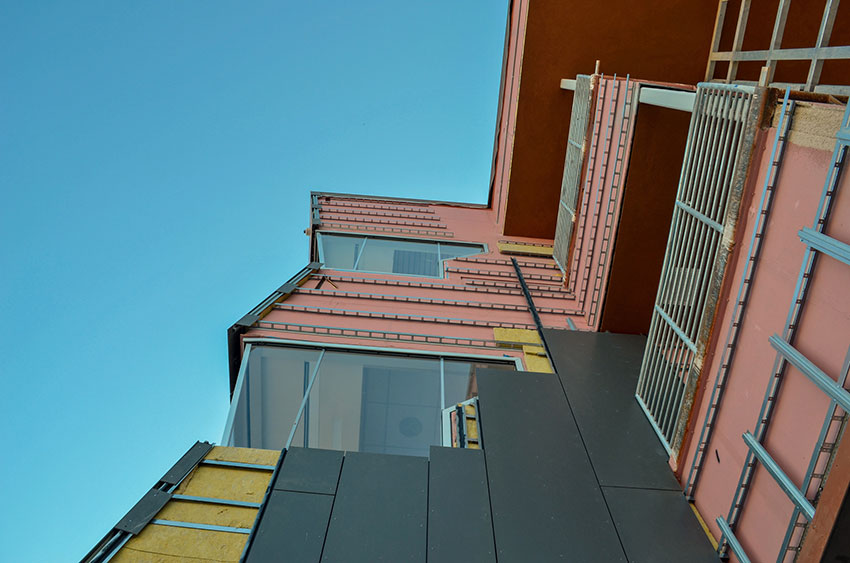
Photo courtesy of Knight Wall Systems
Opting for steel as a material in cladding attachment and support systems means selecting a strong, durable, conscious material.
The material chosen for the cladding support system can be critical to the performance of the wall assembly. The most common materials used are aluminum, steel, stainless steel, or Fiberglass Reinforced Polymer (FRP). Each of these materials have their strengths and weaknesses, but steel stands tall with its broad range of attributes making it the perfect, familiar, material for the job.
Meeting the Thermal Needs
A major factor in specifying a rainscreen attachment system is its impact on energy usage and performance. Namely the impact on thermal transfer at opaque wall assemblies.
Two primary, baseline building energy codes may be adopted by states and local jurisdictions to regulate the design and construction of new buildings: the International Energy Conservation Code® (IECC) and the ANSI/ASHRAE/IESNA Standard 90.1 Energy Standard for Buildings except Low-Rise Residential Buildings.
Driven by a desire to decrease CO2 emissions, escalating energy costs, and resultant increases in building operating expenses, energy codes are becoming increasingly stringent. The overall goal of these policies is to increase the performance of the wall assembly in resisting the transfer of thermal energy so that the conditioned space requires less work from the HVAC system in order to maintain desirable conditions, thereby reducing the amount of energy needed to maintain a conditioned space. This drive has been the key factor in the proliferation of rainscreen assemblies utilizing cladding support systems.
Over the past 20 years, we have increased the opaque wall insulation requirements substantially across all climate zones and for all opaque wall element types. In fact, DOE analysis indicates buildings meeting the 2021 IECC vs the 2018 IECC would result in over 9 percent energy savings overall.
Designing effective insulation is then the necessary strategy for achieving energy efficiency and meeting code, rather than simply increasing insulation amounts. One of the most effective strategies to achieve this is the use of exterior insulation. How exterior insulation is applied to a building can have a dramatic effect on the thermal performance of the wall assembly. But how do we attach cladding to a wall assembly when we have insulation on the outside? Enter the cladding support system…
Thermal Bridging in Walls
It has long been understood that typical metal stud wall assemblies with fluffy, batt, insulation in between has horrendous insulating values. Why is this? Because the solid metal framing members interrupt the insulation and create a pathway for heat to transfer. Heat, much like water, finds the path of least resistance and travels along. The insulation offers much resistance to the heat, but the metal studs offer a highway for the heat to travel along and bypass the insulation. This thereby reduces the actual insulating effects of the wall by 50 percent. Adding exterior insulation can solve the problem if done correctly. The exterior insulation will cover the studs, and building as a whole, much like a coat covers a person’s body. This solid wrap of insulation has dramatic effects on the building’s ability to retain, or repel, heat-reducing HVAC usage and boosting energy savings.
But first, we must understand what actually contributes to conductive thermal transfer in an assembly. Factors include the contact area of the connected materials, the cross-sectional area of the material penetrating the insulation, and the conductivity of the material penetrating the insulation and between adjoining materials. Therefore, simply adding more insulation may not increase the effective R-value without addressing the root factors.
Applying these factors to a cladding support system selection, or design, can generate a great result for thermal performance. One could simply choose the lowest conductive material, but this would result in a loss of other crucial performance criteria, such as structural and fire, both of which are generally viewed as higher priorities in design. And remember, thermal conductivity is only one piece of a complex equation. In fact, thermally isolated cladding support systems primarily comprised of steel have been proven to be one of the most thermally efficient designs, including surpassing systems using clips made entirely of low conductive FRP. How is this?
- EXAMPLE: a wall assembly of Interior Gypsum with Steel Studs 16” OC; Exterior Gypsum, and R-16.8 nominal exterior insulation. That assembly using FRP clips with 16” x 26” spacing has an effective R-value of 15.7, a 26 percent loss. Thermally isolated steel brackets, placed 16” x 24”, result in an effective R-value of 17.2, or a loss of insulating ability of 17 percent.
The thermally isolated system deploys a multi-prong approach to combat thermal bridging. First, the brackets are smaller with a special shape to reduce the cross section penetrating the insulation. This is feasible due to the strength of the steel. Secondly, the steel brackets use specially designed plastic pieces between the metal components and even the back-up wall. This plastic is there to slow the transfer of thermal energy between the conductive materials. Lastly, the design of the plastic pieces is specific to reduce the contact area between materials; if it does not touch, it cannot transfer. When all this is put together, we witness a dramatic increase in performance.
Another example of deploying this strategy is a thermally isolated steel Z-furring. Here, the web of the steel Z-furring is punched to reduce the cross section of steel penetrating the insulation by up to 75 percent. Again, this is feasible due to the strength of the steel. Then a specially designed plastic piece is placed between the Z and the back-up wall to slow heat transfer. Lastly, the plastic piece is hollow with only ribs connecting the front and back again, if it does not touch it cannot transfer. This thermally isolated Z-Furring results in an effective R-value of 17.2 when spaced at 24” OC with a steel stud wall and R-16.8 nominal exterior insulation.
Can’t Be Too Strong
Arguably the most important aspect of any building design is strength. Is it structurally sound and is it safe? Two of the most important questions we must always ask of everything we build. If an assembly cannot remain intact and in good service condition, the fire performance, thermal performance or even sustainability measurements of a material little matter. And with regards to life safety, this is of utmost importance.
The most strenuous work the cladding support system must do is all strength-based. As mentioned, the key role of the cladding support system is to support the cladding and connect it to the building. In order for the system to do this, it must be able to resist the loads imposed upon it without deforming or catastrophically failing. The loads it must always resist are the weight of the cladding itself and the wind pressures acting upon the cladding. Other loads it must resist in certain circumstances include the ability to remain intact under seismic activity, ice loads, and/or snow loads. The latter is highly dependent upon the cladding type and details of the building.
With the system constantly being loaded in a repeated fashion, choosing steel for the material is a natural choice, once again due to its familiarity–and rightfully so. Compared to all the common materials used in cladding support systems discussed, it is by far the strongest and most resilient material of the bunch. It is also easy to design with as we have been designing buildings with steel for over a century.
Steel offers dimensional stability naturally. Changes in moisture content and changes in relative humidity do not impact it. Expansion and contraction are minimal. In fact, according to the American Society of Mechanical Engineers (ASME) B31.3 standard, FRP expansion is 2.5 times more than carbon steel, on average. And aluminum is over 50 percent greater than steel. This one attribute can have catastrophic consequences if not accounted for in the design and installation of the cladding support system.
Other attributes of steel include not warping, splitting, cracking, or undergoing long-term creep when simple, industry-wide, design standards are followed. Steel’s strength-to-weight ratio far surpasses those of FRP and aluminum. It attains a higher strength versus FRP – ultimate flexural strength well in excess of 50 ksi vs 30 ksi on average for FRP. To that end, steel has a ductile failure mechanism versus brittle failure which avoids sudden catastrophic failure in a system. Brittle failure modes of FRP and aluminum alloys require higher safety factors, reducing the allowed load on a component versus a ductile material such as steel. Overall, steel is a safer product for structural support, such is the case with a cladding support system. Steel provides long-term, consistent performance, as it is isotropic, providing equal strength and dimensional properties in any direction. In contrast, FRP products are anisotropic, meaning that their strength is different in different directions. A product, or shape, may be strong in one particular direction of loading but is unlikely to have much strength in the perpendicular direction.
Will It Last?
The cavity of a rainscreen is exposed to the elements. It is a moist environment. And the cladding support system resides in this space, so durability and longevity must be considered.
Contrary to perception, steel offers resistance to pests and mold and can certainly offer corrosion resistance. Building codes and industry standards require that steel used in buildings be designed to tolerate corrosion or be protected against corrosion where corrosion may impair strength or serviceability. Technological advances in coating are dramatically increasing steel’s defense against corrosion.
Galvanized steel is the most common material that comes to mind for most when thinking of steel. This form of steel comes in varying degrees of corrosion resistance by varying the coating thickness. G60 and G90 are the most common thicknesses commercially used. This approach to corrosion protection is outdated, but unfortunately, it is familiar and where most minds go when thinking about the longevity and durability of steel. But things have been changing.
One better option is 55 Al-Zn coated steel (ASTM A792), commonly referenced in the industry as Galvalume, with a grade of AZ55. This is not a new coating by any stretch of the imagination, but not the most common either. AZ55 coated steel has displayed up to three times the life span of G90 galvanized in the harshest marine atmosphere and over five times in moderate atmospheres. The coating composition of 55 percent aluminum and 45 percent zinc provides corrosion resistance via the presence of microscopic aluminum-rich areas within the coating, which corrode very slowly, and zinc-rich areas, which provide galvanic protection.
Arguably the best coating gaining popularity is Zinc-Aluminum-Magnesium, commonly referred to as ZAM produced to ASTM A1046. ZAM has outperformed all current steel coatings in a variety of salt-spray tests and has even gained a reputation as being the bridge between stainless and heavy galvanized coatings. ZAM is a highly corrosion-resistant hot-dip-coated steel that has a coating layer comprised of zinc, 6 percent aluminum, and 3 percent magnesium. A Zn-Al-Mg (ZAM) coating of equal thickness lasts up to 14 times that of typical galvanizing (G90) treatment based on salt-spray testing (ASTM B117) and long-term, real-world, exposure testing. ZAM has superior corrosion resistance on bend-processed parts, cut edge, scratches, and in ammonia environments. ZAM also requires a thinner coating than other metallic coatings for the same life expectancy, reducing cost and benefiting the environment. This steel is by far the most versatile, longest lasting, commercially available on the market, ensuring a quality cladding support system installation for decades to come.
By contrast, FRP products are widely seen to only have a 20- to 25-year lifespan, although conditions of application can shorten or lengthen given weather and exposure. Numerous studies have examined the effects of weathering on FRP products and without the use of proper resins, coatings, and engineered design, the effects of weathering can dramatically reduce the strength of the FRP over time. Thus it is important to thoroughly understand the make-up, and manufacturing quality control, of any FRP product when used in a sensitive manner such as a cladding support element.
Superpower is defined as the ability to exert influence; powerful; great capability. Exterior walls, in their own right, serve a great purpose. At a minimum, they have one goal: to separate and protect the interior environment from the exterior environment. But there are many ways to build an exterior wall. Some design practices may warrant debate as to their resilience or effectiveness. However, one approach is widely agreed upon as the most practical and effective way to “superpower” the exterior wall: the rainscreen principle.
A rainscreen wall assembly can ultimately be viewed as a building envelope support system. This system acts as an overall system, as it groups components to provide a solution for water management, among other benefits. It performs the key responsibilities required of an exterior wall─keeping the interior space dry, warm, and physically protected─while also bringing a true sense of superpower to the exterior wall. Rainscreens are effective at aiding in the management of liquid water and water vapor, they provide exceptional opportunities for energy-efficient performance via continuous insulation and reductions in thermal bridging, and they can be tough enough to stand up to mother nature. At the center of all this, figuratively and literally, one key element of the rainscreen assembly arguably must do most of the work: the cladding support system. Selecting a rainscreen support system that bolsters this efficiency, durability, and performance is paramount.
This article explores the essential elements of a rainscreen, what the cladding support system must do in concert with other rainscreen elements, and important considerations to make during the design process, including building code changes and thermal efficiency.
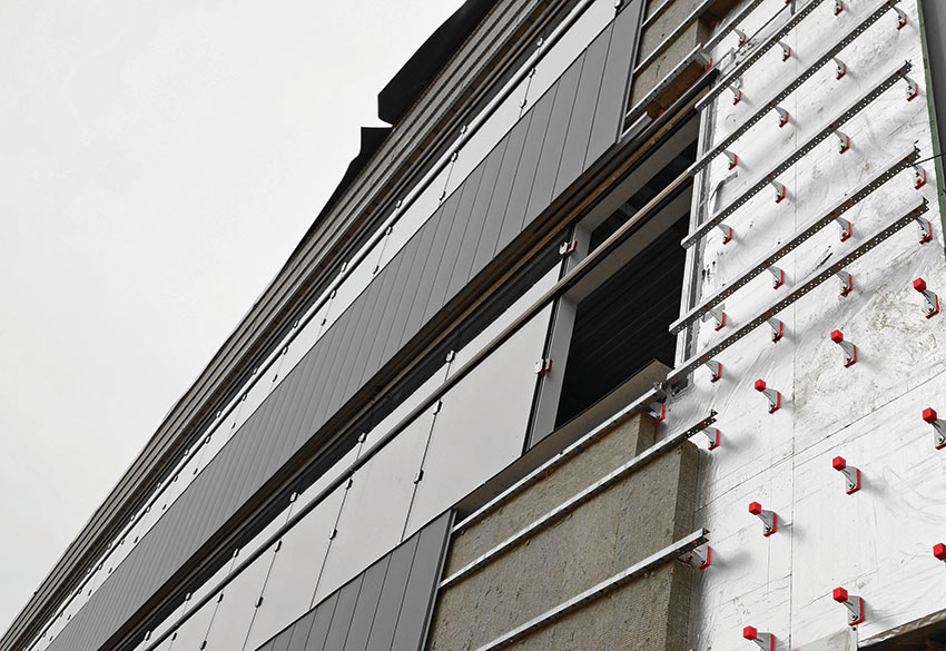
Photo courtesy of Knight Wall Systems
Rainscreen cladding support solutions today can offer exceptional variety for ultimate performance. The system shown is a thermally improved and isolated steel clip and rail cladding support system with mineral wool insulation and zinc metal panels.
SHELTER IN THE STORM: PRESERVING DESIGNED PERFORMANCE WITH RAINSCREENS
A rainscreen, at a very basic level, is defined by the Rainscreen Association in North America (RAiNA) as an assembly applied to an exterior wall which consists of, at minimum, an outer layer, an inner layer, and a cavity between them sufficient for the passive removal of liquid water and water vapor. In other words, a rainscreen is an exterior wall where the cladding is offset from the back-up wall, creating an appropriately sized cavity for ventilation and drainage where liquid water can physically exit (drain) and/or evaporate (ventilation).
Assemblies that fall into this definition range from masonry, simple single skin metal panel assemblies, to clip and rail systems with face-fastened panels of fiber cement or high-pressure laminates. The 2024 edition of the International Building Code (IBC), available for review now, will for the first time officially codify this definition.
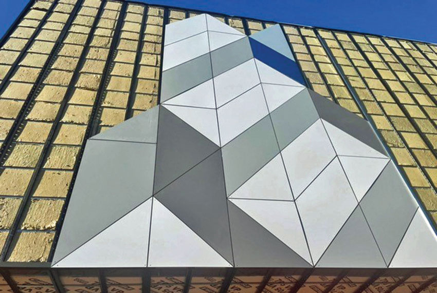
Photo courtesy of Knight Wall Systems
Thermally improved and isolated steel rail system with open-joint, face-fastened, large-format panels.
The Rainscreen in Operation
In general, a rainscreen’s operation allows any water that may pass by or through the cladding to easily drain away from the building, and the air that moves between the cladding and the wall accelerates evaporation of any residual moisture through passive ventilation.
Thus, the primary function of a rainscreen is not to provide barrier protection against water penetration, such as a water-resistant barrier does, but rather to limit the amount of water that could potentially come into contact with the building envelope’s water-resistant barrier.
Additionally, rainscreens have been proven to provide a solution for improving a building’s energy efficiency by providing the space for, and use of, exterior insulation. Thermally isolated rainscreen solutions provide a solution for attaching nearly any type of cladding to extremely efficient support systems, including offering an installation solution for true continuous insulation. This dramatically increases the energy efficiency of the building to meet, and often, exceed code requirements.
Elements of a Rainscreen
Rainscreen assemblies typically consist of multiple components, or elements. Each of these elements serve a specific purpose in supporting, and empowering, the exterior wall to carry out its duties. Not all elements described here are required to produce a rainscreen design, however in the modern era these elements are most commonly seen.
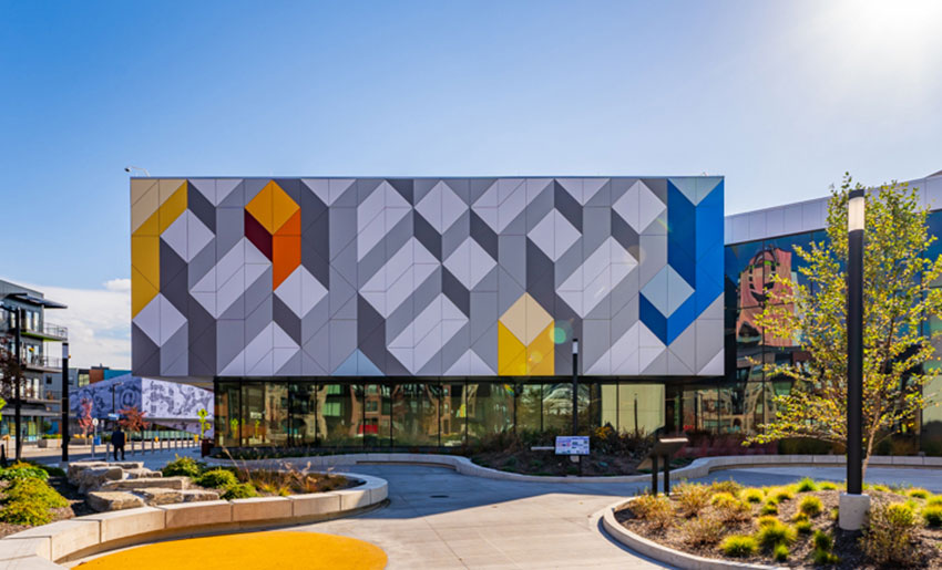
Photo courtesy of Ledgerwood Creative
Strong National Museum of Play, following completion of construction. Rainscreen installation of face-fastened panels.
Cladding, according to RAiNA, is defined as a "non-load bearing wall element, inclusive of any coating and/or finish, serving as the outer layer, which is unprotected from exterior environmental conditions.” Many examples of cladding exist, including brick veneer, metal panels, fiber cement, terra cotta, and others. Cladding is the outermost element of any exterior wall and with a rainscreen assembly, that is no different. Aside from good looks and stimulating visuals, the cladding has much work to do. It absolutely must withstand the harshness of mother nature and be tough enough to physically protect the interior environment – much like an exoskeleton.
It is the first line of defense against water, where upwards of 99% of the water can be shed away in typical designs. Fire protection is also an inherent and very important function of cladding; where flames may be adjacent to the cladding, its ability to ignite and propagate flame on a vertical surface become very important and not overlooked.
The cladding support system, otherwise known as the attachment system, furring system, subframing system, clip and rail system, grid system, or simply girts or rails, all serve the same general purpose. They must facilitate a way for the cladding to be attached to the back-up wall, or the structure. The desire to include this element in a rainscreen design is most often linked to the use of exterior insulation for boosting energy efficiency. This element, too, has much work to do. It resides in a moist environment, behind the cladding, and must have the capacity to withstand all the loads passed on from the cladding, which include the weight of the cladding itself, negative and positive wind pressure, seismic reactions from holding the cladding in place during an earthquake, and, potentially, even ice or snow loads (depending on cladding type and detailing). It must be resilient and durable so it may last many decades as servicing this component is inherently difficult given the concealed location behind the cladding. Resistance to fire must not be overlooked. Depending upon the chosen material, the components themselves could heavily contribute to the spread, or intensity, of a fire. In addition, the geometry of the air cavity created with the system will certainly have profound effects on fire performance.
While the air cavity is obviously not a physical element, it is arguably the most important part of the rainscreen assembly. It is where “the magic happens” and all superpowers come to life! Water that may pass through the cladding can be gulped up by the cavity and expelled through drainage and ventilation. However, larger is not better. In fact, studies indicate the increase in drainage and ventilation performance becomes insignificant once the cavity is over ¾ inch to 1 inch in size.
Exterior insulation will reside in the cavity created by the cladding support system, although the entire cavity must not be filled so the rainscreen superpowers can stay in full effect. It is important for the insulation to be capable of withstanding a moist environment. Many insulations exist for this specific purpose and include types such as rigid foam board, rigid mineral wool boards, and semi-rigid mineral wool.
Another element of a rainscreen assembly is the water control layer, which may be more commonly known as the Water Resistant Barrier (WRB), generally found on the surface of the back-up wall. This is the last line of defense against water making its way into the interior environment. Although, due to the powers at play from the rainscreen, this control layer should have minimal work to do. It is often said, and observed, that the water control layer only has to defend against roughly 0.1 percent of the water contacting the exterior wall. In modern design, the water control layer is often also the air control layer, which is beneficial for the performance of the building overall but also the rainscreen.
The last and final element of all rainscreen assemblies is the back-up wall which is the wall where the rainscreen is applied. This back-up wall, often referred to as the substrate, can be a steel or wood stud wall with sheathing, concrete masonry units (CMU), simple concrete, or cross-laminated timber (CLT). Yet the back-up wall provides more than just something to attach everything to. It must be stiff enough to not cause damage to other components and be structurally adequate to withstand the loads transferred to it.
Accessories and other minor components exist and will serve important, vital, roles. These include flashing, trim pieces, and fasteners, to name a few.
SELECTING FOR RESILIENCE: CLADDING ATTACHMENT AND SUPPORT SYSTEMS
It is often said–and demonstrated–that humans are creatures of habit. As a species, we tend to gravitate towards the familiar, especially in times of duress or when the costs of failure may be high. There is comfort in the known, being able to predict an outcome or do something quickly, accurately, and with confidence. Change is not bad and in fact, it is often warranted and needed, however, one must be vigilant and take great care when enacting change. In fact, a person can gravitate towards the familiar while still accomplishing a new goal or objective, especially if the consequences of failure are great.
A material choice can be an easy door to open for change, however, the choice, when made, can have a large impact on many factors of the design such as durability, resilience, fire safety, and strength. The building industry has extreme familiarity with many materials due to their long histories, proven track records, and even past failures. One of the most and arguably best-known materials in construction is steel. Mankind has been using steel for thousands of years in one form or another. It is absolutely noncombustible, very resilient to changing conditions, one of the strongest industrial materials available, and has been proven to be quite durable when done properly.
Photo courtesy of Knight Wall Systems
Opting for steel as a material in cladding attachment and support systems means selecting a strong, durable, conscious material.
The material chosen for the cladding support system can be critical to the performance of the wall assembly. The most common materials used are aluminum, steel, stainless steel, or Fiberglass Reinforced Polymer (FRP). Each of these materials have their strengths and weaknesses, but steel stands tall with its broad range of attributes making it the perfect, familiar, material for the job.
Meeting the Thermal Needs
A major factor in specifying a rainscreen attachment system is its impact on energy usage and performance. Namely the impact on thermal transfer at opaque wall assemblies.
Two primary, baseline building energy codes may be adopted by states and local jurisdictions to regulate the design and construction of new buildings: the International Energy Conservation Code® (IECC) and the ANSI/ASHRAE/IESNA Standard 90.1 Energy Standard for Buildings except Low-Rise Residential Buildings.
Driven by a desire to decrease CO2 emissions, escalating energy costs, and resultant increases in building operating expenses, energy codes are becoming increasingly stringent. The overall goal of these policies is to increase the performance of the wall assembly in resisting the transfer of thermal energy so that the conditioned space requires less work from the HVAC system in order to maintain desirable conditions, thereby reducing the amount of energy needed to maintain a conditioned space. This drive has been the key factor in the proliferation of rainscreen assemblies utilizing cladding support systems.
Over the past 20 years, we have increased the opaque wall insulation requirements substantially across all climate zones and for all opaque wall element types. In fact, DOE analysis indicates buildings meeting the 2021 IECC vs the 2018 IECC would result in over 9 percent energy savings overall.
Designing effective insulation is then the necessary strategy for achieving energy efficiency and meeting code, rather than simply increasing insulation amounts. One of the most effective strategies to achieve this is the use of exterior insulation. How exterior insulation is applied to a building can have a dramatic effect on the thermal performance of the wall assembly. But how do we attach cladding to a wall assembly when we have insulation on the outside? Enter the cladding support system…
Thermal Bridging in Walls
It has long been understood that typical metal stud wall assemblies with fluffy, batt, insulation in between has horrendous insulating values. Why is this? Because the solid metal framing members interrupt the insulation and create a pathway for heat to transfer. Heat, much like water, finds the path of least resistance and travels along. The insulation offers much resistance to the heat, but the metal studs offer a highway for the heat to travel along and bypass the insulation. This thereby reduces the actual insulating effects of the wall by 50 percent. Adding exterior insulation can solve the problem if done correctly. The exterior insulation will cover the studs, and building as a whole, much like a coat covers a person’s body. This solid wrap of insulation has dramatic effects on the building’s ability to retain, or repel, heat-reducing HVAC usage and boosting energy savings.
But first, we must understand what actually contributes to conductive thermal transfer in an assembly. Factors include the contact area of the connected materials, the cross-sectional area of the material penetrating the insulation, and the conductivity of the material penetrating the insulation and between adjoining materials. Therefore, simply adding more insulation may not increase the effective R-value without addressing the root factors.
Applying these factors to a cladding support system selection, or design, can generate a great result for thermal performance. One could simply choose the lowest conductive material, but this would result in a loss of other crucial performance criteria, such as structural and fire, both of which are generally viewed as higher priorities in design. And remember, thermal conductivity is only one piece of a complex equation. In fact, thermally isolated cladding support systems primarily comprised of steel have been proven to be one of the most thermally efficient designs, including surpassing systems using clips made entirely of low conductive FRP. How is this?
- EXAMPLE: a wall assembly of Interior Gypsum with Steel Studs 16” OC; Exterior Gypsum, and R-16.8 nominal exterior insulation. That assembly using FRP clips with 16” x 26” spacing has an effective R-value of 15.7, a 26 percent loss. Thermally isolated steel brackets, placed 16” x 24”, result in an effective R-value of 17.2, or a loss of insulating ability of 17 percent.
The thermally isolated system deploys a multi-prong approach to combat thermal bridging. First, the brackets are smaller with a special shape to reduce the cross section penetrating the insulation. This is feasible due to the strength of the steel. Secondly, the steel brackets use specially designed plastic pieces between the metal components and even the back-up wall. This plastic is there to slow the transfer of thermal energy between the conductive materials. Lastly, the design of the plastic pieces is specific to reduce the contact area between materials; if it does not touch, it cannot transfer. When all this is put together, we witness a dramatic increase in performance.
Another example of deploying this strategy is a thermally isolated steel Z-furring. Here, the web of the steel Z-furring is punched to reduce the cross section of steel penetrating the insulation by up to 75 percent. Again, this is feasible due to the strength of the steel. Then a specially designed plastic piece is placed between the Z and the back-up wall to slow heat transfer. Lastly, the plastic piece is hollow with only ribs connecting the front and back again, if it does not touch it cannot transfer. This thermally isolated Z-Furring results in an effective R-value of 17.2 when spaced at 24” OC with a steel stud wall and R-16.8 nominal exterior insulation.
Can’t Be Too Strong
Arguably the most important aspect of any building design is strength. Is it structurally sound and is it safe? Two of the most important questions we must always ask of everything we build. If an assembly cannot remain intact and in good service condition, the fire performance, thermal performance or even sustainability measurements of a material little matter. And with regards to life safety, this is of utmost importance.
The most strenuous work the cladding support system must do is all strength-based. As mentioned, the key role of the cladding support system is to support the cladding and connect it to the building. In order for the system to do this, it must be able to resist the loads imposed upon it without deforming or catastrophically failing. The loads it must always resist are the weight of the cladding itself and the wind pressures acting upon the cladding. Other loads it must resist in certain circumstances include the ability to remain intact under seismic activity, ice loads, and/or snow loads. The latter is highly dependent upon the cladding type and details of the building.
With the system constantly being loaded in a repeated fashion, choosing steel for the material is a natural choice, once again due to its familiarity–and rightfully so. Compared to all the common materials used in cladding support systems discussed, it is by far the strongest and most resilient material of the bunch. It is also easy to design with as we have been designing buildings with steel for over a century.
Steel offers dimensional stability naturally. Changes in moisture content and changes in relative humidity do not impact it. Expansion and contraction are minimal. In fact, according to the American Society of Mechanical Engineers (ASME) B31.3 standard, FRP expansion is 2.5 times more than carbon steel, on average. And aluminum is over 50 percent greater than steel. This one attribute can have catastrophic consequences if not accounted for in the design and installation of the cladding support system.
Other attributes of steel include not warping, splitting, cracking, or undergoing long-term creep when simple, industry-wide, design standards are followed. Steel’s strength-to-weight ratio far surpasses those of FRP and aluminum. It attains a higher strength versus FRP – ultimate flexural strength well in excess of 50 ksi vs 30 ksi on average for FRP. To that end, steel has a ductile failure mechanism versus brittle failure which avoids sudden catastrophic failure in a system. Brittle failure modes of FRP and aluminum alloys require higher safety factors, reducing the allowed load on a component versus a ductile material such as steel. Overall, steel is a safer product for structural support, such is the case with a cladding support system. Steel provides long-term, consistent performance, as it is isotropic, providing equal strength and dimensional properties in any direction. In contrast, FRP products are anisotropic, meaning that their strength is different in different directions. A product, or shape, may be strong in one particular direction of loading but is unlikely to have much strength in the perpendicular direction.
Will It Last?
The cavity of a rainscreen is exposed to the elements. It is a moist environment. And the cladding support system resides in this space, so durability and longevity must be considered.
Contrary to perception, steel offers resistance to pests and mold and can certainly offer corrosion resistance. Building codes and industry standards require that steel used in buildings be designed to tolerate corrosion or be protected against corrosion where corrosion may impair strength or serviceability. Technological advances in coating are dramatically increasing steel’s defense against corrosion.
Galvanized steel is the most common material that comes to mind for most when thinking of steel. This form of steel comes in varying degrees of corrosion resistance by varying the coating thickness. G60 and G90 are the most common thicknesses commercially used. This approach to corrosion protection is outdated, but unfortunately, it is familiar and where most minds go when thinking about the longevity and durability of steel. But things have been changing.
One better option is 55 Al-Zn coated steel (ASTM A792), commonly referenced in the industry as Galvalume, with a grade of AZ55. This is not a new coating by any stretch of the imagination, but not the most common either. AZ55 coated steel has displayed up to three times the life span of G90 galvanized in the harshest marine atmosphere and over five times in moderate atmospheres. The coating composition of 55 percent aluminum and 45 percent zinc provides corrosion resistance via the presence of microscopic aluminum-rich areas within the coating, which corrode very slowly, and zinc-rich areas, which provide galvanic protection.
Arguably the best coating gaining popularity is Zinc-Aluminum-Magnesium, commonly referred to as ZAM produced to ASTM A1046. ZAM has outperformed all current steel coatings in a variety of salt-spray tests and has even gained a reputation as being the bridge between stainless and heavy galvanized coatings. ZAM is a highly corrosion-resistant hot-dip-coated steel that has a coating layer comprised of zinc, 6 percent aluminum, and 3 percent magnesium. A Zn-Al-Mg (ZAM) coating of equal thickness lasts up to 14 times that of typical galvanizing (G90) treatment based on salt-spray testing (ASTM B117) and long-term, real-world, exposure testing. ZAM has superior corrosion resistance on bend-processed parts, cut edge, scratches, and in ammonia environments. ZAM also requires a thinner coating than other metallic coatings for the same life expectancy, reducing cost and benefiting the environment. This steel is by far the most versatile, longest lasting, commercially available on the market, ensuring a quality cladding support system installation for decades to come.
By contrast, FRP products are widely seen to only have a 20- to 25-year lifespan, although conditions of application can shorten or lengthen given weather and exposure. Numerous studies have examined the effects of weathering on FRP products and without the use of proper resins, coatings, and engineered design, the effects of weathering can dramatically reduce the strength of the FRP over time. Thus it is important to thoroughly understand the make-up, and manufacturing quality control, of any FRP product when used in a sensitive manner such as a cladding support element.
UP TO THE CHALLENGE: ACHIEVING SUSTAINABILITY WITH STEEL ATTACHMENT SYSTEMS
The material for a cladding support system impacts its sustainability. Steel’s strength, predictability, and durability make it an inherently resilient design material. Additionally, it helps satisfy environmental goals.
Steel is sustainable and is the most recycled material on Earth. Steel products are 100 percent recyclable at the end of their useful lives. Once produced, steel can be continually recycled into new steel products─a steel beam can become another steel beam, or a food can, refrigerator, or roof panel.1 The sourcing of steel by country and process significantly affects the embodied emissions of steel building materials.2 The American steel industry is the least carbon-intensive of all major steel-producing countries. Steel is typically fabricated off site, reducing on-site labor, cycle time, and construction waste.
Most structural steel produced in North America contains 93 percent or more recycled steel.3 Steel framing typically contains a minimum of 25 percent recycled steel and is continually recyclable. It is a versatile, strong, and long-lasting material. Steel’s inherent durability and recyclability make it an ideal fit for the no-waste circular economy.
In addition to its inherent material attributes, steel meets green building program requirements.
Product Declarations
Environmental Product Declarations, or EPDs, are documents that summarize the results of a life cycle assessment (LCA) for specific products. The latest USGBC green building ratings program─LEED V4─includes credits for buildings that use products for which EPDs have been developed. The steel industry actively supports the transparent reporting of environmental impacts associated with construction products. Many rating systems (LEED V4), standards (ASHRAE 189.1), green building codes (IgCC), and specific customers require the submission of environmental product declarations (EPDs) for products delivered to the project site. These EPDs rely on the results of life-cycle assessments to provide information on a number of environmental impacts related to the manufacture of the product, including global warming potential, ozone depletion, acidification, eutrophication, and ozone creation.
The Steel Framing Industry Association (SFIA) works with mill members to develop industry-wide EPDs for steel produced in the United States. In addition to quantifying the impacts of the mill processes, it is also required that producers quantify the industry average environmental impacts per ton of the fabrication process.
The low environmental impacts of fabricated steel are vetted by third parties and transparently disclosed in EPDs. The scope of EPD is cradle-to-gate, including raw material extraction and processing, transportation, steel manufacture and hot dip galvanization, transportation to manufacturing facilities, and steel framing products manufacture. For cold-formed steel framing (CFS), the contributions to total impact indicator results are dominated by the raw material extraction and production stage, primarily from HDG (Hot Dip Galvanized) steel production. The manufacturing process of CFS contributes significantly to its sustainability after extraction. During fabrication, the steel is rolled into desired shapes and cut into ordered lengths, minimizing waste. This precise production also reduces the amount of energy required and minimizes the environmental impact associated with traditional steel fabrication processes. Because steel is 100 percent recyclable, cold-formed steel can be recycled multiple times without losing its strength or durability, making it a highly sustainable material. Additionally, CFS framing can be deconstructed by hand and reused with minimal damage.
Specifiers can encourage the transparent disclosure of fabricated steel's environmental impacts by requiring the submission of EPDs in their bid packages.
Certain manufacturers may provide further product documentation, such as a Declare Label from the International Living Future Institute™. Manufacturers voluntarily disclose product information on Declare labels, which are designed to provide clear information. These labels report all product ingredients and use a simple color code system to flag chemicals of concern. Further information is provided on the product’s final assembly locations, life expectancy, end-of-life options, and overall compliance with relevant requirements of the Living Building Challenge (LBC).
Product transparency and certifications are essential building blocks for whole-building certification. Steel rainscreen attachment systems with EPDs and other product disclosures can help achieve points in several leading green building programs.
Green Building Certifications
The Living Building Challenge addresses development on all fronts, with the core underlying principle being that buildings should mimic nature and natural systems. Toxic materials (Red List Chemicals) are not permitted on projects and LBC aims to eliminate their use. A flower metaphor is used to illustrate that all elements of the built environment are rooted in place. The Petals of the Living Product Challenge has specific Imperatives that define the actions needed to achieve that Petal.
The WELL Building Standard is an evidence-based system for measuring, certifying, and monitoring the performance of building features that impact health and well-being. It is also the world’s first building standard focused exclusively on human health and wellness. The standard is divided into 10 concepts: Air, Water, Nourishment, Light, Movement, Thermal Comfort, Sound, Materials (specifically deals with material transparency), Mind, and Community.
Steel rainscreen attachment systems also are recognized under LEED. LEED v4.1 addresses materials through Fostering Material Sourcing & Transparency through Building Product Disclosure & Optimization credits, aimed at increasing market transparency concerning the sourcing & contents of Materials. The environmental benefits of steel framing, particularly high recycling rates, recycled content, and steel’s inert, non‐organic nature, make key contributions to achieving LEED certification. Specific LEED credit categories for steel include Materials and Resources (MR): Building Life Cycle Impact Reduction, MR: Building Product Disclosure and Optimization – Environmental Product Declarations, MR: Building Product Disclosure and Optimization – Sourcing of Raw Materials, MR: Building Product Disclosure and Optimization – Material Ingredients, MR: Design for Flexibility, MR: Construction and Demolition Waste Management, Indoor Environmental Quality (EQ) Credit: IAQ Assessment, and IN Credit: Innovation.
THE STRENGTH TO PROTECT: LIFE SAFETY AND TESTING IMPLICATIONS FOR RAINSCREEN ATTACHMENT SYSTEMS
Rainscreen systems have largely been absent from the International Building Code (IBC), until now. This does not mean the use of a rainscreen system on an exterior wall had no requirements or standards to meet. But they could possibly have been overlooked. Various elements of a rainscreen system have certainly been included.
Terms
As mentioned at the onset, Rainscreen System is now defined within the IBC. This may seem to be of little consequence at first glance, however, the use of the term is now proliferated throughout the code. How so? A Rainscreen System is included, explicitly, as an example of an Exterior Wall Assembly. Consequently, everywhere Exterior Wall Covering is used within the code, Rainscreen System could essentially be substituted for the term.
Loads
The IBC has an entire chapter dedicated to exterior walls because they are very important. Within this chapter, several general requirements must be met. The most important requirement of exterior walls is to be designed and constructed to safely resist the superimposed loads required by Chapter 16. This verbiage has been present for many cycles. However, in 2024, Section 1402.3 expands the requirement from beyond the broad term of the exterior wall to also include exterior wall coverings (rainscreen systems) amongst other elements. Therefore, this would include evaluations for the cladding and the cladding support systems that make up the rainscreen system. As mentioned, the system design typically evaluates wind load, dead load, and seismic load. Attachment design can include engineering and/or tested assemblies whereby the test proves the ability of the assembly to resist the loads that will be on the building. Given the broad nature of designs within the commercial industry, relying on testing is difficult as configurations of the cladding and the support system behind it change from project to project. Therefore, engineering analysis is by far the more economical and efficient approach to satisfying the requirements. Essentially, it is imperative for the cladding support system to be designed, and specifying this requirement can help ensure this critical requirement is met.
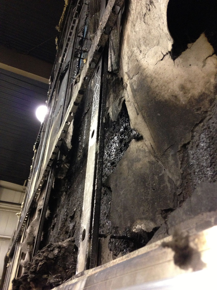
Photo courtesy of Knight Wall Systems
Example of an intact continuous structural connection, post fire test.
Fire Safety
Second only to structural performance, fire performance is of utmost importance. A key life safety focus is the NFPA (National Fire Protection Agency) 285 fire-test requirement for multi-story, noncombustible construction. Recent developments in ASHRAE, IECC, and LEED have increased interest in high-performance building envelope designs with continuous insulation, which commonly involve combustible plastic foam. In the U.S., fire regulations are issued by government agencies and reference codes such as a building code, which in turn reference fire test methods and acceptance criteria. Fire safety is regulated by a combination of active and passive fire protection measures. Passive fire protection involves the use of products that are unlikely to generate a serious fire under their expected use. Active fire protection involves the use of methods to reduce or prevent the spread and effects of fire, heat, or smoke by means of detection and/or suppression of the fire.
US codes typically require that composite assemblies be fire tested, both as individual combustible components and in addition to as a complete assembly. With the increased use of thick foam insulation in sustainable, energy-efficient designs, architects should be aware that all foam plastic insulations used in exterior wall assemblies are required to pass all seven elements of Chapter 26 of the IBC, including Section 2603.5.5, which requires compliance with NFPA 285. Foam plastic insulation manufacturers should provide verification that products are part of an approved NFPA 285 assembly. It is important to note that the NFPA 285 standard fire test is an assembly test, not a component test. The details of the test assembly and application materials should be strictly followed in practice.
Other requirements for NFPA 285 fire test exist, such as the use of a combustible cladding material such as Metal Composite Material or High-Pressure Laminate. Additionally, FRP products may require NFPA 285 in their own right depending on configuration and size. In addition to the possibility of requiring an NFPA 285 tested assembly, Section 2613 requires the FRP product to bear the label of an approved agency, indicating the end use will comply with code requirements. The label and identification applied on an FRP product by the manufacturer need to contain the name of the manufacturer, the function and performance characteristics of the product or material, and the name of the identification of an approved agency that indicates that the representative sample of product or material has been tested and evaluated by an approved agency. Because FRP may include hundreds of different combinations of fiber, polymer, and processes, FRP products have very specific code requirements that must be met to be an acceptable and approved system. Additionally, currently, no ASTM standard exists for governing FRP products in an attachment application.
Combining fire with strength of materials is another consideration. The epoxy used in an FRP can soften or possibly melt in temperatures as low as a few hundred degrees, whereas the fibers themselves can stand temperatures well within the range of a typical fire. However, the strength of an FRP is a combination of both the epoxy and fibrous strand, so the loss of one can be catastrophic since the component in the context of this article would be supporting the weight of the cladding through a fire event.
Steel and Fire Codes
Steel is noncombustible, so the material does not contribute to the ignition of fires, the spread of fires, or the size and severity of fires, thereby reducing risks to occupants, firefighters, and property and business owners. In fact, no fire codes or listing requirements exist within the IBC related to steel. In a fire, the resilient steel element and its connection to the structure will not melt or become disconnected, which would result in a catastrophic failure. This can be referred to as a continuous noncombustible structural connection, which describes the preservation of the connection in the event of a fire.
CONCLUSION
Rainscreen systems superpower the exterior wall. One of the most important elements of this superpower, the cladding support system, can magnify this by using steel with its inherent properties of strength, resilience and fire resistance. Thermally isolated and improved steel rainscreen attachment systems enable a project to conform to building and energy codes quite easily. These types of systems, when properly designed and implemented, will easily meet, and even surpass stringent performance requirements. The intrinsic capabilities of steel also allow rainscreen systems to satisfy building code requirements that directly impact the design and construction of buildings and their cladding support system. The familiar is something not to lose.
RESOURCES
“Sustainability”. Build Using Steel, American Iron and Steel Institute. 2023. Accessed June 27, 2023.
“Emission Omissions: Carbon accounting gaps in the built environment.”. International Institute for Sustainable Development. 2019. . Accessed June 27, 2023.
“Sustainability.”. American Institute of Steel Construction. https://www.aisc.org/why-steel/sustainability/. Accessed June 27, 2023.
Brian Nelson is a graduate of Oregon State University with 15 years of rainscreen facade experience and has secured multiple patents. He currently serves as the General and Technical Manager at Knight Wall Systems as well as the Building Codes Committee Co-Chair for the Rainscreen Association in North America. He consistently collaborates with project teams, providing solutions to challenges in rainscreen facade design.