This CE Center article is no longer eligible for receiving credits.
Fluid-applied Membrane Materials
One of the increasingly popular product category choices for barrier materials in exterior wall construction is the use of fluid-applied membranes. This type of product has been used and proven for years particularly on below-grade walls with considerable success. It is essentially a spray, trowel, or roller applied compound that cures to a complete and continuous layer that can act as both an air barrier and water-resistive barrier (A/WRB). With growing interest in using this rather high-performance solution on walls of all sorts, different formulations have become available made from different core materials.
There are two general things to realize with this type of barrier system. First, the thickness of the application will vary based on the core materials used in its makeup. However, there is a common misperception that thicker applications will be better which is not necessarily so as we will see in further discussion. Second, these materials, like all other air and water-resistive barriers, are usually installed after the sheathing is in place but before final cladding, windows, or doors are installed, meaning that they remain exposed to the weather for some period of time. Fortunately, the makeup of most of the fluid-applied membranes is such that it will not break down or deteriorate when exposed to weather or sunlight as is sometimes the case with other A/WRBs. However there is always the need to protect the edges of any A/WRB installation. In sheet systems, blowing wind can cause edges to come loose or tear and allow debris to get behind the system. In fluid-applied systems, most of those concerns are eliminated, but the edges where the fluid application stops should be protected or covered to prevent any damage to the installation.
With the above in mind, we can look more closely at the two common types of fluid-applied membranes, namely asphalt based and polymer based.
Asphalt-Based Systems
Liquefied asphalt is the traditional material that has been used with or without some modifiers to achieve certain characteristics for water protection. The most notable characteristic about it is that it requires a thick application on the order of at least 60 – 80 mils to be effective as an A/WRB. It is common then for installers and building inspectors to measure the thickness in the field to assure that it qualifies as a code-compliant, effective barrier. This thicker application, in part, contributes to its “nail sealability”—the ability of the material to remain intact by sealing around a nail or other fastener that penetrates through the membrane to the wall construction. ASTM D1970 is the test used for testing the nail sealability, but it is really a test for roofing products, meaning that it is not directly replicating wall conditions. Nonetheless, it has become the accepted standard until something new can be developed.
There are some other characteristics about asphalt-based fluid-applied membranes worth noting. From a sustainability standpoint, they obviously rely on fossil fuels to create the oil-based asphalt. Their impact is not just at the product creation stage of their life cycle, but also at the end of life stage when the materials it is adhered to need be disposed of in a manner appropriate to other petroleum-based products. From a wall assembly standpoint, they need to be fully covered and protected as part of an overall assembly and tested in order to pass the NFPA 285 fire test. Further, asphalt may or may not be compatible with certain cladding or wall covering systems, particularly an exterior insulation and finish system (EIFS). Similarly, it is not compatible with un-faced rigid plastic insulation that may be used to meet thermal requirements for continuous insulation.
Polymer-Based Systems
In response to the limitations of other air and water-resistive barriers, fluid-applied systems that are polymer based instead of asphalt based have become readily available. Despite the obvious difference in material makeup, the most noticeable difference in its application is its much thinner coating that produces excellent results. Instead of the 60-80 mils sought in asphalt applications, polymer-based systems produce the same or better performance in only 9 -12 mils with a wet film thickness of approximately 20 mils. While this may seem like a small difference, in fact it is an 80 percent reduction or better of material. Multiplying that difference all across the wall surface of a building can amount to significant time, labor, and cost savings since it can go on quicker and more economically overall.
The makeup of the polymer produces a number of desirable characteristics to achieve a truly continuous, high-quality barrier system in exterior walls. Specifically, polymer-based systems, similar to some asphalt-based systems, have been tested and approved as both an air barrier and a water-resistive barrier, meaning that both functions can be performed with a single application. However, in response to varying needs and unlike asphalt products, they can be formulated to be either vapor permeable or non-permeable as a wall assembly system may require. Applied wet and allowed to dry, they create a truly continuous A/WRB without any seams or joints plus the ability to seal around all penetrations. Since there is no asphalt, they are fully compatible with virtually all cladding systems including EIFS—although each EIFS manufacturer has their own proprietary product. As part of a full wall assembly, they can meet all code requirements including the fire test requirements of NFPA 285.
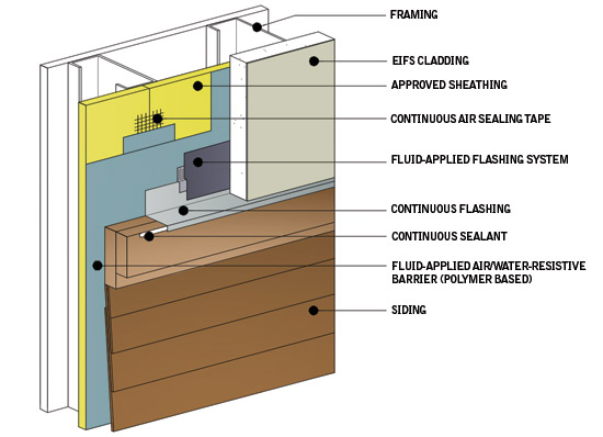
Image courtesy of Dryvit Systems, Inc.
When a polymer-based fluid-applied membrane is incorporated and tested as part of an overall wall assembly, it can meet all pertinent code requirements for wall integrity, energy efficiency, and fire.
From an installation standpoint, polymer-based systems also have a number of advantages. As a water-based system, they are safer for workers to use and much more environmentally friendly. Since it is a single A/WRB product, it can be installed over the entire wall surface by one trade. In the event of difficult or challenging installations, polymer-based systems have been found to be more forgiving of surface conditions such as substrate moisture compared to asphalt-based materials. All of this contributes to the ability for manufacturers to offer a fully warranted system if approved installers are used.
Specifying Polymer-based Air and Water Barriers
Based on all of the above, here are a few things to take into account when specifying polymer-based A/WRBs. First, the ABAA makes a case for specifying them in a distinct specification section. Often they are included as part of another section related to wall finish or construction which may or may not be appropriate if the air or water-resistive barrier is installed by a separate trade. Fluid-applied membrane air barriers are listed as a separate section in the Master Format in Division 7 Thermal and Moisture Protection under section 07 27 26. If they are part of an EIFS system, the AWRB should be specified in the same section as EIFS to ensure compatibility as well as maintaining warranties for the owner. If a non-adhered cladding is used, the AWRB can be specified separately from the cladding.
The General, Part 1 portion of the specification should cite all of the code referenced standards discussed in this article for air barrier products and assemblies. Further, ABAA certification can be requested on both the material and the wall system as may be available. Where required due to building height, evidence that the assembly meets NFPA 285 fire testing should also be indicated. When it comes to project conditions for storing materials in terms of environmental factors such as temperature, humidity, etc., then manufacturers' information should be cited since individual products vary. Warranties are available and can be specified, but will also vary between manufacturers.
The Products or Part 2 portion of the specification will generally be very straightforward. The fluid-applied membrane material itself should be specified as a flexible, polymer-based, non-cementitious, combination water-resistive membrane and air barrier. Some manufacturers offer choices of textured or smooth finish and a spray option. The appropriate selection should be made accordingly primarily based on the substrate material and the cladding covering. Any accessory materials related to flashing or interfacing with windows, doors, etc. should also be specified here and be supplied by the same manufacturer to assure that a complete, continuous system is achieved.

Photo courtesy of Dryvit Systems, Inc.
Properly designing exterior wall systems and specifying appropriate barrier systems will help keep air and water outside while contributing to the long and beneficial use of the building.
The Execution or Part 3 portion of the specification section should not be underestimated since this is where the performance is either assured or compromised. An experienced, qualified subcontractor should be performing the work and should begin with a thorough examination of the walls. The sheathing/substrate should be fully complete and ready to receive the fluid-applied membrane. All building flashing that is to drain off of the A/WRB should be in place and all openings, penetrations, and special conditions should be appropriately prepared and ready for treatment. The nature of the thinner polymer-based coatings may be unfamiliar to some building inspectors or whole building commissioning agents. In those cases, it may be appropriate to consider a mock up or test area to establish a standard of acceptance for the project. Since mil gage testing will be based on a thinner coating than asphalt-based products, it may be appropriate to consider using manufacturer coverage rates to establish an acceptable performance basis. Once these things are reviewed and agreed upon, then full application and coverage can be performed on the entire building. Once complete, the finished A/WRB should not be left exposed to the weather for more than 30 days primarily to protect the interface areas with other materials, flashings, and openings.
Conclusion
The benefits of polymer-based, fluid-applied air and water-resistant barriers have been realized in thousands of projects. Understanding how they differ from other fluid-applied barrier materials, particularly in terms of thickness and complete, continuous sealing ability, allows for ready code compliance and assurance that they are meeting the appropriate standards. Overall they help provide better exterior wall design and performance over the life cycle of the building.
Peter J. Arsenault, FAIA, NCARB, LEED AP, practices architecture, consults on green and sustainable design, writes on technical topics, and presents nationwide on all of the above. www.linkedin.com/in/pjaarch
 |
Outsulation® by Dryvit is a fully tested, code-compliant EIFS, providing an air/water-resistive barrier, exterior CI, and durable finishes to buildings worldwide. Outsulation offers lower construction costs, improved energy efficiency, and long-term sustainability compared to other exterior walls. The final appearance can look like brick, stucco, metal, granite, and limestone. www.dryvit.com |
The design and performance of exterior walls has received a lot of deserved attention in recent years. Building science research, code updates, and sustainable building design innovation have all contributed to greater understanding and implementation of best practices related to air, water, and vapor barriers in exterior walls. All three of these barriers are important to not only control energy usage in buildings but also to assure the longevity and durability of a wall system across its life cycle. Nonetheless, the growth in available information can cause confusion on what really works in a particular wall assembly in a particular climate. Worse, in a rapidly changing industry, building and design professionals sometimes rely on outdated information and fail to recognize the benefits of the latest, well-tested and proven products or systems.
International Building Code—Leading the Way on Wall Performance
During the past few decades, the International Building Code (IBC) has been regularly updated to be much more specific regarding requirements for exterior wall construction. Some of these are prescriptive requirements meaning that compliance is based on following a prescribed level of performance that may vary by location or situation. For example, if we were discussing fire egress requirements in a commercial building, we would see that the number of exit doors required by the IBC is calculated based on prescriptive requirements related to occupancy, area, and use. By contrast other code requirements are simply mandatory regardless of situation, meaning that they must be present and they must meet minimum standards of performance. In our egress example, the presence of opening protectives (automatic door closers) is a mandatory code requirement on every exit door regardless of other factors. When it comes to exterior walls, air, water, and vapor barriers fall into the mandatory category—all are required in virtually all cases with only one variable for vapor barriers based on location.

Photo courtesy of Dryvit Systems, Inc.
Exterior walls of all types need to meet updated code requirements for continuous barriers against air, water, and vapor.
IBC Definitions
Recognizing that there has been some confusion on the role and function of air, water, and vapor barriers as related to wall construction, the committee of professionals involved in writing and updating the codes spend considerable time and effort on establishing appropriate definitions for code-mandated elements. Specifically, the latest (2012) version of the International Building Code includes in Chapter 2, Section 202 a number of relevant definitions as part of the list of standard definitions used in the code. These include specific definitions for exterior walls, vapor barriers (as contrasted with a vapor permeable membrane), and water-resistant barriers (WRBs). For the sake of consistency, we will use the same terms with the same meanings throughout this article. (See sidebar below.)
IBC Exterior Wall Requirements
Chapter 14 of the IBC describes the particulars for exterior walls including mandatory performance requirements (IBC 1403). In clear and certain terms, it states that “Exterior walls shall provide the building with a weather-resistant exterior wall envelope.” It goes on to require that “The exterior wall envelope shall include flashing … (and) shall be designed and constructed in such a manner as to prevent the accumulation of water within the wall assembly by providing a water-resistive barrier behind the exterior veneer … and a means for draining water that enters the assembly to the exterior.” Keeping in mind that this is all about the general integrity of the exterior wall, the clear intent is to avoid damage to the wall from water and weather by requiring the use of flashing, a water-resistive barrier, and drainage for any water that does penetrate. There are some exceptions listed for concrete or masonry walls or exterior insulation and finish systems (EIFS) provided other relevant portions of the IBC are followed. There is also an exception for showing compliance for drainage through testing as prescribed in the code (IBC 1403.2). Some details of these requirements are elaborated on as follows:
Image courtesy of International Code Council
Chapter 14 of the International Building Code requires that exterior walls be constructed for integrity and protection against water and vapor.
▶ Flashing. The mandatory and prescriptive details of flashing are specifically called out to “be installed in such a manner so as to prevent moisture from entering the wall or to redirect it to the exterior. Flashing shall be installed at the perimeters of exterior door and window assemblies, penetrations and terminations of exterior wall assemblies, exterior wall intersections with roofs, chimneys, porches, decks, balconies and similar projections, and at built-in gutters and similar locations where moisture could enter the wall.” (IBC 1405.4) Properly detailed and installed flashing is clearly a must.
▶ Fire testing of water-resistive barriers. The code recognizes that the use of a water-resistive barrier cannot compromise the fire and flame propagation requirements of the rest of the code. Hence it states: “Exterior walls on buildings of Type I, II, III or IV construction that are greater than 40 feet (12,192 mm) in height above grade plane and contain a combustible water-resistive barrier shall be tested in accordance with and comply with the acceptance criteria of NFPA 285.” (IBC 1403.5) The cited test is NFPA 285: Standard Fire Test Method for Evaluation of Fire Propagation Characteristics of Exterior Non-Load-Bearing Wall Assemblies Containing Combustible Components. This test applies to an entire wall assembly that contains any combustible products. The intent is to determine if the entire assembly, not just any particular product, can be declared safe under specific fire conditions. As such, compliance is determined not by testing an individual material but a full assembly.
▶ Vapor barriers. Looking at the total wall assembly, the code states “Protection against condensation in the exterior wall assembly shall be provided…” (IBC 1403.2) which recognizes the damage potential from vapor condensing in an exterior wall and deteriorating construction materials through rot, rust, or mold. Hence the code goes on to require, based on the IBC definitions, that “Class I or II vapor retarders shall be provided on the interior side of frame walls in Zones 5, 6, 7, 8 and Marine 4.” (IBC 1405.3) Zones are determined by looking in the International Energy Conservation Code (IECC) but the requirement for its inclusion remains in the IBC. The IBC does allow for some cases where Class III vapor retarders can be used depending on the wall construction details (IBC 1405.3.1).
International Energy Conservation Code—Raising the Bar
While the IBC establishes the basic requirements for exterior walls from a general building construction sense, the 2012 International Energy Conservation Code (IECC) goes further to address energy use in buildings. The beauty of the family of codes prepared by the International Code Council (ICC) is the coordination between them, meaning that these two codes have been painstakingly reviewed to complement and not contradict each other among concurrent versions. Hence the IECC uses similar format and language to the IBC but also acknowledges the need to coordinate requirements.
IECC Definitions
The IECC uses the same general building definitions as the IBC but goes on to add a few that are specific to energy conservation. Among them are air barriers, which are recognized as a significant deterrent to air infiltration flowing through exterior wall systems. Such air flow is understood to alter the indoor air makeup of a building such that it will cause heating and cooling systems within a conditioned space to work harder and use more energy. It can also contribute to people inside the building being less comfortable and adjusting the thermostat set points to compensate but using more energy in the process. Note that the IECC clarifies that both above-grade and below-grade walls are part of its definition of exterior walls.
IECC Air Barrier Requirements
There are specific, mandatory requirements for air barriers that are addressed for both residential and commercial buildings in the IECC. The commercial building requirements are actually less stringent and detailed than the requirements for residential buildings but far reaching and thorough nonetheless in terms of the thermal envelope—including exterior walls. Also, it should be noted that compliance with the IECC can be demonstrated either by following the provisions of the code directly or by showing compliance with ANSI/ ASHRAE / IESNA Standard 90.1. While the overall energy performance of buildings is generally the same between the different compliance methods, there are differences in details, including differences in detailed requirements for air barriers. For this discussion, we will be focused on the IECC compliance path.
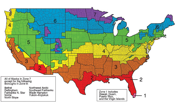
Image courtesy of International Code Council
The International Energy Conservation Code indicates climate zones and requires the use of air barriers as an energy conservation measure.
▶ Air barrier location. The IECC makes it very clear that “A continuous air barrier shall be provided throughout the building thermal envelope.” (IECC C402.4.1) That means all surfaces including walls. It goes on to say “The air barriers shall be permitted to be located on the inside or outside of the building envelope, located within the assemblies composing the envelope, or any combination thereof.” Typically, air barriers are placed on the outside of the wall assembly to prevent air infiltration from entering the assembly. Placing the air barrier on the outside of the walls also makes it much easier to maintain continuity across floors, ceilings, demising walls, etc.
▶ Air barrier continuity. The IECC imposes several mandatory requirements for the construction and use of an air barrier, including that it “shall be continuous for all assemblies that are the thermal envelope of the building and across the joints and assemblies.” (IECC C402.4.1.1) Further, recognizing the importance of joints and seams, the code requires “Air barrier joints and seams shall be sealed, including sealing transitions in places and changes in materials.” Similarly, at all penetrations, “the air barrier shall be caulked, gasketed, or otherwise sealed in a manner compatible with the construction materials and location.” (IECC C402.4.2) In all cases, joints, seams, seals, and penetrations “shall be securely installed in or on the joint for its entire length so as not to dislodge, loosen, or otherwise impair its ability to resist positive and negative pressure from wind, stack effect, and mechanical ventilation.” Achieving this performance requires attention to detail not just in design but in construction as well.
▶ Air permeability. The IECC relies on ASTM testing for the determination of a material or assembly to be considered an air barrier. Specifically ASTM E2178 Standard Test Method for Air Permeance of Building Materials establishes air permeability for a particular material to be no greater than 0.004 cfm/ft2 (0.02 L/s • m2) under a pressure differential of 0.3 inches water gauge (w.g.) (75 Pa). This threshold is based on historical requirements used in Canada and based on the amount of air that penetrates through a sheet of gypsum wallboard. Turning from a single material to an air barrier assembly, the threshold is not as strict but still a significant level to achieve. ASTM E2357 Standard Test Method for Determining Air Leakage of Air Barrier Assemblies and ASTM E1677 Standard Specification for Air Barrier (AB) Material or System for Low-Rise Framed Building Walls are cited by the IECC for assembly compliance. In these cases, an average air leakage not to exceed 0.04 cfm/ft2 (0.2 L/s • m2) under a pressure differential of 0.3 inches of water gauge (w.g.) (75 Pa) is required. Going from 4 thousandths to 4 hundredths of a cubic foot per minute might seem to be a big difference but the net number is still very small. Its significance lies in the fact that all of the joints, seams, connections, etc. need to be included in the test to be sure that the total assembly does indeed perform as a complete, un-breached air barrier.
Air Barrier Association of America—Offering Clarity
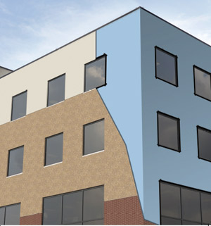
Photo courtesy of Dryvit Systems, Inc.
Continuity of an air barrier (shown in blue under final cladding) is required across all floors, around all openings, and at all penetrations.
The Air Barrier Association of America (ABAA) is a not-for-profit trade organization dedicated to advancing knowledge about air barriers. Founded in 2001, it is a membership-based association with a diverse makeup of manufacturers, suppliers, distributors, architects, engineers, contractors, researchers, testing and audit agencies, consultants, and building owners. While their first focus has been on air barriers, they more recently have begun to address water-resistive barriers as well. The association seeks to raise the standard of proficiency and effectiveness of the industry through quality assurance programs, education, lobbying, and marketing of the industry to government, the professional community, building owners, utilities, and other industry stakeholders. Among the messages they have conveyed, they point out that the U.S. Department of Energy has stated that up to 40 percent of the energy used to heat and cool a building is due to uncontrolled air leakage.
ABAA has become recognized as a go-to source for all things related to air barriers by the general design, construction, and manufacturing community. For design professionals, they provide technical information on air barriers, guide specifications, and accredited continuing education on relevant topics. For manufacturers they offer a product evaluation process whereby manufactured air barriers and/or water-resistive barriers and assemblies can be accredited and approved by the ABAA. In this regard they indicate that the performance of an air barrier assembly is of far greater importance than the air permeance of an individual material since a highly rated material won't matter much if the joints, seams, and penetrations are letting air through. For contractors and installers, they offer quality assurance training for field-installed systems including accreditation and certification for those who demonstrate proficiency. In short, they have become the recognized certification source for all aspects of designing, manufacturing, and installing air barriers and water-resistive barriers in thermal envelopes.
Conventional Barrier Materials
All of these criteria are important and establish the basis for performance and code compliance, but ultimately it comes down to selecting and using certain materials in a wall construction assembly. As might be expected, there are numerous choices that have been traditionally used and accepted for each of the barrier systems we are discussing. It is worth pointing out that different materials can provide a singular air barrier function, a vapor barrier function, or a water-resistive barrier function. There are also materials that can provide a combination of two or even all of these three functions.
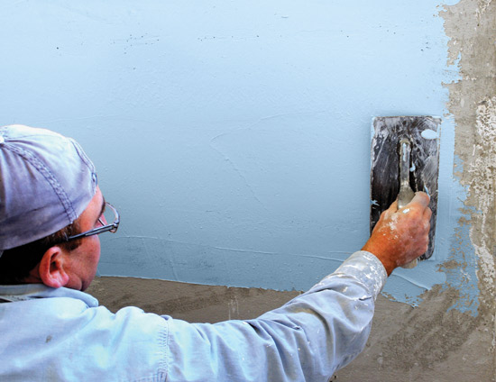
Photo courtesy of Dryvit Systems, Inc.
Fluid-applied membrane systems can be applied to an appropriate substrate by using a trowel, a roller, or a sprayer as field conditions may warrant.
Common Vapor Barriers
The IBC recognizes that there has been considerable discussion and debate over what is an acceptable vapor barrier material. It therefore first allows certified testing of a material or assembly to demonstrate the perm ratings of the three different vapor retarder classes. In addition the IBC identifies specific acceptable materials for each Class: (IBC 1405.3.2)
▶ Class I: Sheet polyethylene, non-perforated aluminum foil.
▶ Class II: Kraft-faced fiberglass batts or paint with a perm rating greater than 0.1 and less than or equal to 1.0.
▶ Class III: Latex or enamel paint.
By virtue of this language, the materials listed above have become commonly used where required or appropriate on the inside of framed walls.
Common Water-Resistive Barriers (WRB)
The IBC identifies two options for WRB materials, first stating: “A minimum of one layer of No. 15 asphalt felt, complying with ASTM D 226 for Type 1 felt…” (IBC 1404.2). Asphalt felt has certainly been a traditional material for many thermal envelope installations including walls and roofs, however it is seen as a rather obsolete material compared to other modern alternatives. The second IBC option is to allow “other approved materials” which refers to “materials that are acceptable to the building official or authority having jurisdiction” (IBC 202) rather than a long list of alternatives. Approval will certainly include demonstrated compliance with air barrier performance but in many applicable cases, also with fire performance as part of an assembly tested by NFPA 285.
Among the more commonly used and approved materials, self-adhered sheet membranes (sometimes call “peel and stick” materials) are prevalent. These have traditionally been used in roofing applications and were also popular on below-grade walls. However, there are a variety of manufacturers and products such that performance varies considerably meaning that they may or may not work as effective water-resistive barriers or effective air barriers for above-grade walls. Another concern is the vapor permeability of these materials. Vapor barriers are required by the IBC on the inside of framed walls (for cold climates) in most cases, not the outside where WRBs are typically required. Hence, if any vapor does make it into the wall it is prevented from escaping to either the inside or outside thus becoming counter-productive to the intent of protecting the wall construction. A class III vapor permeable WRB is preferable then to allow any trapped moisture to migrate out while still protecting the wall from water. Hence the use of self-adhered sheet membranes is also becoming rather obsolete in walls in favor of other approved materials that have a more desirable vapor permeability rating. Among them are mechanically attached flexible sheets made of non-woven materials that can provide water resistance and may also function as an air barrier depending on the manufacturer and product. Of course, the penetration of the mechanical fasteners compromises the continuity of the barrier and different manufacturers try to address that in different ways, some with better success than others.
Common Air Barrier Materials
The ABAA recognizes several categories of material types, namely self-adhered sheet air barriers, liquid-applied membranes, medium-density sprayed polyurethane foam, mechanically fastened commercial building wraps, and board-stock air barriers. They will test and certify all of these recognizing that they can all perform well if installed properly using air barrier accessories (i.e. sealants, tapes, and transition membranes) assembled together to form a continuous barrier. However, there are practical limits and other considerations in particular building projects that can determine which type will work best. The IECC recognizes this and allows tested demonstration of performance but also lists no less than 15 different common construction materials that can be treated as acceptable air barriers “provided joints are sealed and materials are installed as air barriers in accordance with the manufacturer's instructions” (IECC C402.4.1.2.1). These materials are consistent with the ABAA categories and include such things as plywood or OSB, foam insulation, gypsum or cement board, roof membranes, concrete products, or metal. While it is easy to see that any of these would certainly inhibit or prevent air flow, the issue of course is the edges and penetrations. There is also the concern of trapped moisture being able to escape since many of these materials will have the same concern as non-permeable WRBs. For these reasons it is easy to see why it has become so common to use a separate sheet over these conventional construction materials to act as a continuous air barrier with some vapor permeability. As noted, some of these sheet products can also double as a water-resistive barrier depending on the manufacturer or product.
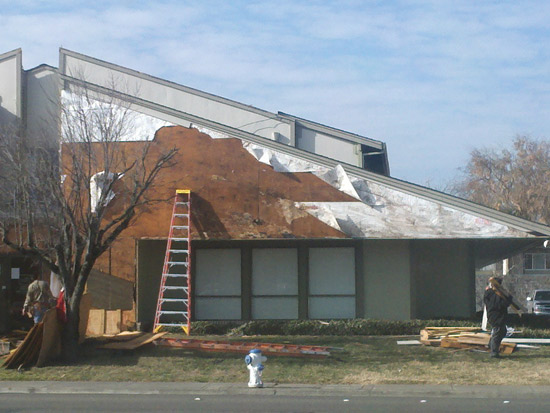
Photo courtesy of Dryvit Systems, Inc.
Conventional sheet type air and water-resistive barriers have limitations based on the method of attachment and sealing of seams and joints.
Fluid-applied Membrane Materials
One of the increasingly popular product category choices for barrier materials in exterior wall construction is the use of fluid-applied membranes. This type of product has been used and proven for years particularly on below-grade walls with considerable success. It is essentially a spray, trowel, or roller applied compound that cures to a complete and continuous layer that can act as both an air barrier and water-resistive barrier (A/WRB). With growing interest in using this rather high-performance solution on walls of all sorts, different formulations have become available made from different core materials.
There are two general things to realize with this type of barrier system. First, the thickness of the application will vary based on the core materials used in its makeup. However, there is a common misperception that thicker applications will be better which is not necessarily so as we will see in further discussion. Second, these materials, like all other air and water-resistive barriers, are usually installed after the sheathing is in place but before final cladding, windows, or doors are installed, meaning that they remain exposed to the weather for some period of time. Fortunately, the makeup of most of the fluid-applied membranes is such that it will not break down or deteriorate when exposed to weather or sunlight as is sometimes the case with other A/WRBs. However there is always the need to protect the edges of any A/WRB installation. In sheet systems, blowing wind can cause edges to come loose or tear and allow debris to get behind the system. In fluid-applied systems, most of those concerns are eliminated, but the edges where the fluid application stops should be protected or covered to prevent any damage to the installation.
With the above in mind, we can look more closely at the two common types of fluid-applied membranes, namely asphalt based and polymer based.
Asphalt-Based Systems
Liquefied asphalt is the traditional material that has been used with or without some modifiers to achieve certain characteristics for water protection. The most notable characteristic about it is that it requires a thick application on the order of at least 60 – 80 mils to be effective as an A/WRB. It is common then for installers and building inspectors to measure the thickness in the field to assure that it qualifies as a code-compliant, effective barrier. This thicker application, in part, contributes to its “nail sealability”—the ability of the material to remain intact by sealing around a nail or other fastener that penetrates through the membrane to the wall construction. ASTM D1970 is the test used for testing the nail sealability, but it is really a test for roofing products, meaning that it is not directly replicating wall conditions. Nonetheless, it has become the accepted standard until something new can be developed.
There are some other characteristics about asphalt-based fluid-applied membranes worth noting. From a sustainability standpoint, they obviously rely on fossil fuels to create the oil-based asphalt. Their impact is not just at the product creation stage of their life cycle, but also at the end of life stage when the materials it is adhered to need be disposed of in a manner appropriate to other petroleum-based products. From a wall assembly standpoint, they need to be fully covered and protected as part of an overall assembly and tested in order to pass the NFPA 285 fire test. Further, asphalt may or may not be compatible with certain cladding or wall covering systems, particularly an exterior insulation and finish system (EIFS). Similarly, it is not compatible with un-faced rigid plastic insulation that may be used to meet thermal requirements for continuous insulation.
Polymer-Based Systems
In response to the limitations of other air and water-resistive barriers, fluid-applied systems that are polymer based instead of asphalt based have become readily available. Despite the obvious difference in material makeup, the most noticeable difference in its application is its much thinner coating that produces excellent results. Instead of the 60-80 mils sought in asphalt applications, polymer-based systems produce the same or better performance in only 9 -12 mils with a wet film thickness of approximately 20 mils. While this may seem like a small difference, in fact it is an 80 percent reduction or better of material. Multiplying that difference all across the wall surface of a building can amount to significant time, labor, and cost savings since it can go on quicker and more economically overall.
The makeup of the polymer produces a number of desirable characteristics to achieve a truly continuous, high-quality barrier system in exterior walls. Specifically, polymer-based systems, similar to some asphalt-based systems, have been tested and approved as both an air barrier and a water-resistive barrier, meaning that both functions can be performed with a single application. However, in response to varying needs and unlike asphalt products, they can be formulated to be either vapor permeable or non-permeable as a wall assembly system may require. Applied wet and allowed to dry, they create a truly continuous A/WRB without any seams or joints plus the ability to seal around all penetrations. Since there is no asphalt, they are fully compatible with virtually all cladding systems including EIFS—although each EIFS manufacturer has their own proprietary product. As part of a full wall assembly, they can meet all code requirements including the fire test requirements of NFPA 285.
Image courtesy of Dryvit Systems, Inc.
When a polymer-based fluid-applied membrane is incorporated and tested as part of an overall wall assembly, it can meet all pertinent code requirements for wall integrity, energy efficiency, and fire.
From an installation standpoint, polymer-based systems also have a number of advantages. As a water-based system, they are safer for workers to use and much more environmentally friendly. Since it is a single A/WRB product, it can be installed over the entire wall surface by one trade. In the event of difficult or challenging installations, polymer-based systems have been found to be more forgiving of surface conditions such as substrate moisture compared to asphalt-based materials. All of this contributes to the ability for manufacturers to offer a fully warranted system if approved installers are used.
Specifying Polymer-based Air and Water Barriers
Based on all of the above, here are a few things to take into account when specifying polymer-based A/WRBs. First, the ABAA makes a case for specifying them in a distinct specification section. Often they are included as part of another section related to wall finish or construction which may or may not be appropriate if the air or water-resistive barrier is installed by a separate trade. Fluid-applied membrane air barriers are listed as a separate section in the Master Format in Division 7 Thermal and Moisture Protection under section 07 27 26. If they are part of an EIFS system, the AWRB should be specified in the same section as EIFS to ensure compatibility as well as maintaining warranties for the owner. If a non-adhered cladding is used, the AWRB can be specified separately from the cladding.
The General, Part 1 portion of the specification should cite all of the code referenced standards discussed in this article for air barrier products and assemblies. Further, ABAA certification can be requested on both the material and the wall system as may be available. Where required due to building height, evidence that the assembly meets NFPA 285 fire testing should also be indicated. When it comes to project conditions for storing materials in terms of environmental factors such as temperature, humidity, etc., then manufacturers' information should be cited since individual products vary. Warranties are available and can be specified, but will also vary between manufacturers.
The Products or Part 2 portion of the specification will generally be very straightforward. The fluid-applied membrane material itself should be specified as a flexible, polymer-based, non-cementitious, combination water-resistive membrane and air barrier. Some manufacturers offer choices of textured or smooth finish and a spray option. The appropriate selection should be made accordingly primarily based on the substrate material and the cladding covering. Any accessory materials related to flashing or interfacing with windows, doors, etc. should also be specified here and be supplied by the same manufacturer to assure that a complete, continuous system is achieved.
Photo courtesy of Dryvit Systems, Inc.
Properly designing exterior wall systems and specifying appropriate barrier systems will help keep air and water outside while contributing to the long and beneficial use of the building.
The Execution or Part 3 portion of the specification section should not be underestimated since this is where the performance is either assured or compromised. An experienced, qualified subcontractor should be performing the work and should begin with a thorough examination of the walls. The sheathing/substrate should be fully complete and ready to receive the fluid-applied membrane. All building flashing that is to drain off of the A/WRB should be in place and all openings, penetrations, and special conditions should be appropriately prepared and ready for treatment. The nature of the thinner polymer-based coatings may be unfamiliar to some building inspectors or whole building commissioning agents. In those cases, it may be appropriate to consider a mock up or test area to establish a standard of acceptance for the project. Since mil gage testing will be based on a thinner coating than asphalt-based products, it may be appropriate to consider using manufacturer coverage rates to establish an acceptable performance basis. Once these things are reviewed and agreed upon, then full application and coverage can be performed on the entire building. Once complete, the finished A/WRB should not be left exposed to the weather for more than 30 days primarily to protect the interface areas with other materials, flashings, and openings.
Conclusion
The benefits of polymer-based, fluid-applied air and water-resistant barriers have been realized in thousands of projects. Understanding how they differ from other fluid-applied barrier materials, particularly in terms of thickness and complete, continuous sealing ability, allows for ready code compliance and assurance that they are meeting the appropriate standards. Overall they help provide better exterior wall design and performance over the life cycle of the building.
Peter J. Arsenault, FAIA, NCARB, LEED AP, practices architecture, consults on green and sustainable design, writes on technical topics, and presents nationwide on all of the above. www.linkedin.com/in/pjaarch
|
Outsulation® by Dryvit is a fully tested, code-compliant EIFS, providing an air/water-resistive barrier, exterior CI, and durable finishes to buildings worldwide. Outsulation offers lower construction costs, improved energy efficiency, and long-term sustainability compared to other exterior walls. The final appearance can look like brick, stucco, metal, granite, and limestone. www.dryvit.com |