Informed design professionals who understand the basics of backflow prevention are able to successfully manage regulations and safely deliver fresh drinking water in their projects. The common response from several architects when asked about the importance of backflow protection was that they “left that up to the mechanical engineer.” These professionals were experts in green design and knowledgeable about the basics of best practices for water conservation. Among them, only a few mentioned their concern for the placement of plumbing controls, maintenance schedules, the locations of access panels, fire safety systems, and cross-connection controls. Reviewing the basics of cross-connection and backflow controls will allow them to partner with their mechanical and plumbing engineers and create strong design teams that will protect drinking water.
All images courtesy of WATTS Water Technologies, Inc.
Cross-connection controls are critical to the protection and conservation of drinking water. The health, safety, and welfare of the public depend on the appropriate design and planning of cross-connection controls in buildings and landscape projects.
The resiliency and safety of a drinking water system may be assured through a basic understanding of the cross-connection controls. These mechanical controls provide the barrier between pollutants and the public supply of fresh drinking water. This course will review the basics of these important mechanical devices, from simple vacuum breakers to detector assemblies for fire sprinkler systems. These devices are usually specified by engineers and added to a project manual with little understanding as to how a lack of knowledge can lead to an overly complicated project delivery.
The early analysis of cross-connection controls includes many advantages to the design professional. These include improved designs for mechanical rooms, better project scheduling, safer site infrastructure, easier permitting, and proper equipment maintenance. An architect who assembles complete project delivery teams will include civil (site infrastructure), mechanical, and plumbing engineers. These professionals should be involved in project planning from initial programming through construction documentation and commissioning.
Protecting Drinking Water from Contaminants
The public water supply is distributed by a series of pipes, storage facilities, and conveyance components. Since the 20th century, these distribution systems are designed and regulated to provide an uninterrupted supply of pressurized safe water to consumers. According to the U.S. Environmental Protection Agency (EPA), public distribution systems span almost 1 million miles in the United States, representing the clear majority of physical infrastructure for water supplies. In addition, public water systems meet fire protection needs for cities, homes, schools, hospitals, businesses, and industry.
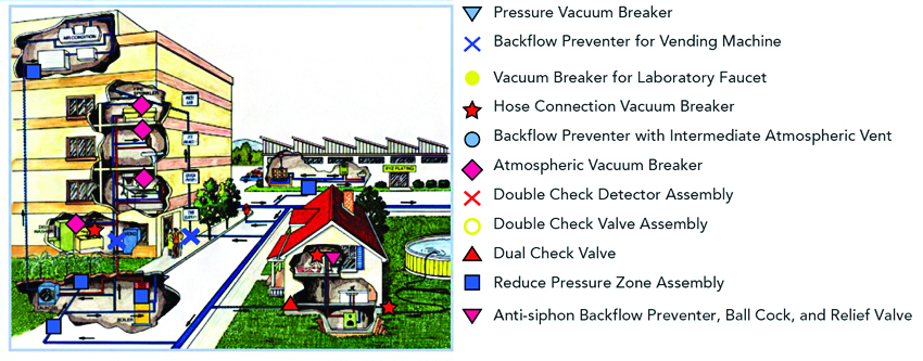
Shown are typical locations of check valves and appropriate backflow prevention systems in a commercial building.
Cross-Connection
A cross-connection, as defined by the EPA, is “any actual or potential connection between the public water supply and a source of contamination or pollution.” Such cross-connections constitute a hazard to the building occupants and can jeopardize the cleanliness and potability of the public water system in the event of a backflow or backsiphonage event. An actual connection is a direct connection to a source of contamination, such as an unprotected boiler connection. An example of a potential connection could be as simple as a hose bib, which could potentially be connected to a pesticide sprayer.
Backflow
Backflow is the unwanted and potentially dangerous reverse flow of liquid, gas, or another substance into a potable water distribution system. According to the EPA, “most backflow incidents are generally detected and reported to the local authority only if customers detect an irregularity in their water supply...but not all contamination that produces illness and disease can be detected by taste, color, or odor.” Each plumbing system is unique, and often contamination is not identified until serious symptoms occur. Backflow can occur outside from hoses, pools, and other exterior equipment, as well as from equipment inside buildings.
Backsiphonage
Backsiphonage is a condition that occurs whenever there is a negative or subatmospheric pressure in the potable supply piping. These conditions typically occur during periods of very high demand in the public water main, which lowers the supply pressure. In some cases, demands imposed by firefighting operations (or in the event of a water main break) will suddenly and significantly lower a city’s water pressure below atmospheric pressure. This pressure change results in a partial vacuum being drawn on the non-potable system. This vacuum will siphon the pollutants or contaminants into the potable water system through an unprotected cross-connection, such as a hose bib or hydronic system make-up connection.
Backpressure
Backpressure is a push from the demand side. This occurs when pressure in a non-potable system is elevated above that of the potable supply, resulting in reverse flow. The installation of pumps, boilers, or other water heating equipment that may cause thermal expansion can results in reverse flow.
Cross-connection controls are critical to the protection and conservation of drinking water. The health, safety, and welfare of the public depend on the appropriate design and planning of cross-connection controls in buildings and landscape projects. This primer will provide an overview of the equipment, testing and permitting processes for cross-connection protection to ensure that public water systems will stay safe.
Degrees of Hazard
Backflow into the public water distribution system can be prevented by eliminating cross-connections or adding backflow preventers. According to the EPA, backflow is not only a threat to the health of our community, but it can also cause damage to our environment. The EPA recognizes that backflow incidents can cause issues such as corrosion of equipment, harmful microbial growth in our distribution systems, and changes in taste, odor, and color of the water supply. Chapter 3 of the EPA’s Water Quality Standards Handbook provides definitions and guidelines for water quality criteria.1 Backflow risks are described as one of two types of hazards. A “pollutant” is any substance that may affect the color, taste, or odor of the potable water but does not pose a direct threat to human health through exposure or consumption of the water. Pollutants may impose an objectionable odor or appearance to the water, but they do not in and of themselves pose a health threat and therefore are considered to be a low hazard, or non-hazard, when compared to contaminants.
A “contaminant” is any substance that, when introduced into the potable water system, constitutes a direct threat to life or health of a human. This can occur through consumption or if the substance is in contact with the skin. A contaminant can be a caustic chemical, a fluid containing bacteria or disease, or any other substance that could threaten human health. Contaminants compose the highest degree of hazard to the potable water system.
The initial stage of an architect’s project is programming. During programming, design professionals analyze the proposed or future uses of a facility and possible connections to water supplies. This is particularly important when reviewing the cross-connections to public water supplies. The selection of backflow prevention system depends on whether the programmed use within a project is considered a low hazard, a non-hazard, or a hazard.
Preventable Backflow Failures
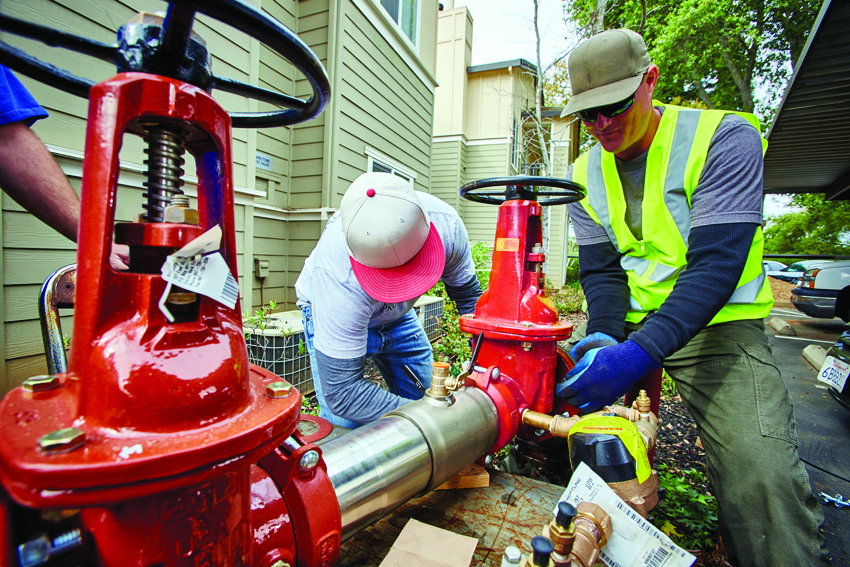
Public health officials have documented numerous incidents of unprotected cross-connections resulting in backflow. Plumbing equipment malfunctions, poor maintenance, and human error provide a litany of frequent opportunities for serious contamination of public drinking water. Many of these incidents are documented in the Cross-Connection Control Manual published by the EPA.2 Some examples include the introduction of such contaminants as gas, blood, sodium hydroxide, heptachlor, pesticides, hexavalent chromium, and antifreeze in incidents that include the poisoning of the potable water in schools, hospitals, and large residential areas. The culprits include improper industrial tank pumping, broken water mains, community water main pressure reduction, frozen backflow preventers, hoses left in swimming pools, and improper gate valve installation. Contamination can occur at any point of connection between a potable water pipe and a source of non-potable water. Legionnaires disease can be caused by contamination from pathogens and bacteria introduced from cooling towers that have been installed or maintained improperly. The case study on the following page is an example of one incident of a preventable backflow failure.
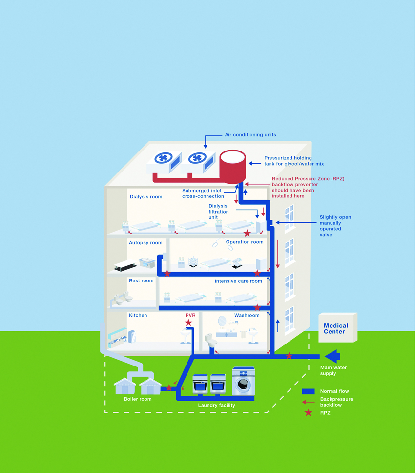
The lack of hydraulic containment in hazardous areas led to serious illnesses and deaths in a health-care facility.
Informed design professionals who understand the basics of backflow prevention are able to successfully manage regulations and safely deliver fresh drinking water in their projects. The common response from several architects when asked about the importance of backflow protection was that they “left that up to the mechanical engineer.” These professionals were experts in green design and knowledgeable about the basics of best practices for water conservation. Among them, only a few mentioned their concern for the placement of plumbing controls, maintenance schedules, the locations of access panels, fire safety systems, and cross-connection controls. Reviewing the basics of cross-connection and backflow controls will allow them to partner with their mechanical and plumbing engineers and create strong design teams that will protect drinking water.
All images courtesy of WATTS Water Technologies, Inc.
Cross-connection controls are critical to the protection and conservation of drinking water. The health, safety, and welfare of the public depend on the appropriate design and planning of cross-connection controls in buildings and landscape projects.
The resiliency and safety of a drinking water system may be assured through a basic understanding of the cross-connection controls. These mechanical controls provide the barrier between pollutants and the public supply of fresh drinking water. This course will review the basics of these important mechanical devices, from simple vacuum breakers to detector assemblies for fire sprinkler systems. These devices are usually specified by engineers and added to a project manual with little understanding as to how a lack of knowledge can lead to an overly complicated project delivery.
The early analysis of cross-connection controls includes many advantages to the design professional. These include improved designs for mechanical rooms, better project scheduling, safer site infrastructure, easier permitting, and proper equipment maintenance. An architect who assembles complete project delivery teams will include civil (site infrastructure), mechanical, and plumbing engineers. These professionals should be involved in project planning from initial programming through construction documentation and commissioning.
Protecting Drinking Water from Contaminants
The public water supply is distributed by a series of pipes, storage facilities, and conveyance components. Since the 20th century, these distribution systems are designed and regulated to provide an uninterrupted supply of pressurized safe water to consumers. According to the U.S. Environmental Protection Agency (EPA), public distribution systems span almost 1 million miles in the United States, representing the clear majority of physical infrastructure for water supplies. In addition, public water systems meet fire protection needs for cities, homes, schools, hospitals, businesses, and industry.
Shown are typical locations of check valves and appropriate backflow prevention systems in a commercial building.
Cross-Connection
A cross-connection, as defined by the EPA, is “any actual or potential connection between the public water supply and a source of contamination or pollution.” Such cross-connections constitute a hazard to the building occupants and can jeopardize the cleanliness and potability of the public water system in the event of a backflow or backsiphonage event. An actual connection is a direct connection to a source of contamination, such as an unprotected boiler connection. An example of a potential connection could be as simple as a hose bib, which could potentially be connected to a pesticide sprayer.
Backflow
Backflow is the unwanted and potentially dangerous reverse flow of liquid, gas, or another substance into a potable water distribution system. According to the EPA, “most backflow incidents are generally detected and reported to the local authority only if customers detect an irregularity in their water supply...but not all contamination that produces illness and disease can be detected by taste, color, or odor.” Each plumbing system is unique, and often contamination is not identified until serious symptoms occur. Backflow can occur outside from hoses, pools, and other exterior equipment, as well as from equipment inside buildings.
Backsiphonage
Backsiphonage is a condition that occurs whenever there is a negative or subatmospheric pressure in the potable supply piping. These conditions typically occur during periods of very high demand in the public water main, which lowers the supply pressure. In some cases, demands imposed by firefighting operations (or in the event of a water main break) will suddenly and significantly lower a city’s water pressure below atmospheric pressure. This pressure change results in a partial vacuum being drawn on the non-potable system. This vacuum will siphon the pollutants or contaminants into the potable water system through an unprotected cross-connection, such as a hose bib or hydronic system make-up connection.
Backpressure
Backpressure is a push from the demand side. This occurs when pressure in a non-potable system is elevated above that of the potable supply, resulting in reverse flow. The installation of pumps, boilers, or other water heating equipment that may cause thermal expansion can results in reverse flow.
Cross-connection controls are critical to the protection and conservation of drinking water. The health, safety, and welfare of the public depend on the appropriate design and planning of cross-connection controls in buildings and landscape projects. This primer will provide an overview of the equipment, testing and permitting processes for cross-connection protection to ensure that public water systems will stay safe.
Degrees of Hazard
Backflow into the public water distribution system can be prevented by eliminating cross-connections or adding backflow preventers. According to the EPA, backflow is not only a threat to the health of our community, but it can also cause damage to our environment. The EPA recognizes that backflow incidents can cause issues such as corrosion of equipment, harmful microbial growth in our distribution systems, and changes in taste, odor, and color of the water supply. Chapter 3 of the EPA’s Water Quality Standards Handbook provides definitions and guidelines for water quality criteria.1 Backflow risks are described as one of two types of hazards. A “pollutant” is any substance that may affect the color, taste, or odor of the potable water but does not pose a direct threat to human health through exposure or consumption of the water. Pollutants may impose an objectionable odor or appearance to the water, but they do not in and of themselves pose a health threat and therefore are considered to be a low hazard, or non-hazard, when compared to contaminants.
A “contaminant” is any substance that, when introduced into the potable water system, constitutes a direct threat to life or health of a human. This can occur through consumption or if the substance is in contact with the skin. A contaminant can be a caustic chemical, a fluid containing bacteria or disease, or any other substance that could threaten human health. Contaminants compose the highest degree of hazard to the potable water system.
The initial stage of an architect’s project is programming. During programming, design professionals analyze the proposed or future uses of a facility and possible connections to water supplies. This is particularly important when reviewing the cross-connections to public water supplies. The selection of backflow prevention system depends on whether the programmed use within a project is considered a low hazard, a non-hazard, or a hazard.
Preventable Backflow Failures
Public health officials have documented numerous incidents of unprotected cross-connections resulting in backflow. Plumbing equipment malfunctions, poor maintenance, and human error provide a litany of frequent opportunities for serious contamination of public drinking water. Many of these incidents are documented in the Cross-Connection Control Manual published by the EPA.2 Some examples include the introduction of such contaminants as gas, blood, sodium hydroxide, heptachlor, pesticides, hexavalent chromium, and antifreeze in incidents that include the poisoning of the potable water in schools, hospitals, and large residential areas. The culprits include improper industrial tank pumping, broken water mains, community water main pressure reduction, frozen backflow preventers, hoses left in swimming pools, and improper gate valve installation. Contamination can occur at any point of connection between a potable water pipe and a source of non-potable water. Legionnaires disease can be caused by contamination from pathogens and bacteria introduced from cooling towers that have been installed or maintained improperly. The case study on the following page is an example of one incident of a preventable backflow failure.
The lack of hydraulic containment in hazardous areas led to serious illnesses and deaths in a health-care facility.
Integrated Design Management: Schematic Design
Twenty-first century buildings are “machines for living, working, and playing,” to paraphrase 20th century architect Le Corbusier. As technology advances, building design management requires a sophisticated, complex team of professionals. Integrated design management teams include all members of the design team who provide a holistic approach to the challenges and opportunities that can occur from schematic design through the commissioning of a project. Teams that include the architect and engineers from the beginning of a project have the advantages of predicting any scheduling issues, from the delivery of components to regulatory delays.
The key elements to a cross-connection control program include the isolation of the domestic water supply and containment at the meter, resulting in total backflow protection through the use of backflow preventers. Isolation requires an analysis of any cross-connections in the project. The appropriate backflow prevention devices will be selected to isolate any hazard to that location and protect the owner’s potable water system from contamination.
Total backflow protection is governed and regulated by The Uniform Plumbing Code (UPC) in Chapter 6, Section 608: Isolation Protection & Containment.4 “Containment” is the containment of a property’s private water system from the city’s drinking water supply system. This is done downstream of a property’s water service connection (the water meter) and achieved by installing a backflow prevention device immediately after the water meter. The water distribution system, fixtures, and piping are also governed by this code. Distribution flow rates and flow pressures are identified in Table 604.3 of the plumbing code.
In schematic design, the regulatory overview of cross-connection controls will impact the size of mechanical rooms, ceiling plenums, and fire safety controls. Regulatory overview will impact scheduling. In the schematic design phase, a review of the key cross-connection controls and permitting requirements will assist with project design and planning.
Agency Approvals and Code Compliance
There is a long history to the regulatory overview of plumbing systems. Although the complex overlapping of authorities may seem confusing, they provide a public water safety net. Design professionals need to understand who the Authority Having Jurisdiction (AHJ) is, as well as regulatory industry standards, particularly critical when the project includes fire safety systems. Typically, the property line divides whether the system is governed by the plumbing code or the AHJ. The American Water Works Association provides a list of some of the responsible water safety enforcement authorities.5
- Local plumbing and building officials enforce all provisions of the applicable plumbing and building codes relative to installation, repair, maintenance, and operation of all plumbing system devices.
- Fire marshals are responsible for regulating fire protection systems (e.g., fire sprinkler systems) downstream of the potable water system supply connection entering the premises.
- Safety inspectors (Occupational Safety and Health Administration [OSHA]; Workers’ Compensation Board [WCB] [Canada]; Mine Safety and Health Administrators [MSHA]) are responsible for inspecting potable water systems (plumbing) for worker safety.
- Health officials are responsible for inspecting restaurants and other food preparation facilities (e.g., dairies), health-care facilities (e.g., nursing homes), etc.
- Agricultural inspectors are responsible for the safe handling of chemicals (e.g., pesticides) used in growing and processing agricultural products. Water purveyors deliver drinking water to customers and will have jurisdiction over water supply systems. These entities are public utility water companies, county water districts, or municipalities that deliver drinking water to customers. The mechanical or plumbing engineer with local knowledge may be the first source for information as to code compliance for cross-connection controls. As a condition of being connected to the public water supply, the municipality or water purveyor will typically have jurisdiction over the containment backflow. A device might be allowed in one county but not the adjacent county, and in one state but not the other. These professionals will also have relationships with the local plumbing inspectors, avoiding misinformation and delays. The basic guiding principles for specifying cross-connection controls depend on the answers to the following questions.
- Is the building area or equipment device considered a health hazard or a non-health hazard?
- Is a testable or non-testable device required?
- Will a pressure vacuum breaker versus a reduced pressure principle device be required for irrigation?
- Is a “not lead-free” system allowed as with certain non-potable applications, such as irrigation or hydronic heating systems?
The answers to these questions will save money, time, and potentially avoid an inspection failure or the installation of a more expensive device when a more economical one would have satisfied the requirements.
The major standards in the industry are: The International Association of Plumbing and Mechanical Officials (IAPMO), the American Society of Sanitary Engineers (ASSE), the University of California Foundation for Cross-Connection Control and Hydraulic Research (USC-FCCCHR), the American Water Works Association (AWWA), and NSF International (formerly the National Sanitation Foundation). These organizations provide information, education, product testing, product evaluations, and certifications.
Backflow preventer installation requires the services of a licensed professional engineer (PE) and licensed master plumber (LMP). A licensed professional will determine if a project requires a backflow preventer or multiple devices, or if the project qualifies for an exemption. The law also typically requires annual testing and inspection by a certified tester, and a report submitted to the Department of Environmental Protection (DEP) or AHJ. Failure to comply can lead to penalties and termination of water service. Backflow preventer devices are made up of moving parts, seals, and springs and are subject to corrosive substances, wear, and fatigue. Selecting the correct device and understanding annual testing and maintenance are just the beginning of a system that will require meeting the regulatory requirement that protects public health, safety, and welfare.
Construction Documents and Specifications
Engineers recognize that there are several major considerations for specifying backflow, including the importance of code compliance and agency approvals. The main elements include flow performance, calculated building flow, and hazard conditions. The resiliency of these devices for future maintenance, repair, and replacements depends on their serviceability, valve size, weight, installation options, shutoff options, and testing ability.
The problems that occur due to inadequate accessibility, lack of shutoffs, and improper orientations can lead to flooding, avoidable expenses for repair, and premature replacement.
Some typical problems include the following examples:
- Inaccessibility due to the improper placement in a nest of plumbing pipes.
- Improper orientation into a plumbing system for which it is not rated.
- The removal of factory-approved parts in testable backflow assemblies that negate testing abilities.
- Incorrectly placed fittings on vacuum breakers on faucets that defeat pressurization controls.
Mechanical rooms must be designed for the proper installation, accessibility, and maintenance of all cross-connection controls. Many of these controls are designed to discharge water during testing and upon failure and should be located where there is an appropriate area for drainage.
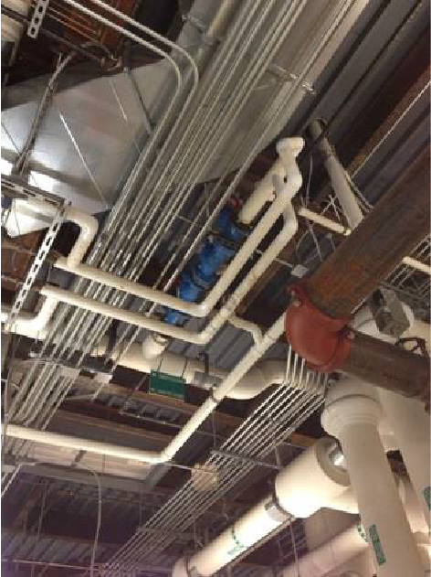
The valve shown in blue is not accessible for testing, a code requirement. This installation will require additional maintenance charges for years to come.
Architect Robert Allen, AIA, associate principal at Bowie Gridley Architects, describes his approach to cross-connection controls as a design challenge. He reports that he is always aware of the necessity for access panels, appropriate fire safety installations, and the visual effect and impact of fixtures in ceilings and walls of these devices. As someone who is engaged with the adaptive reuse of historic buildings as well as historic preservation, he is aware of the importance of analyzing the existing mechanical infrastructure of these systems. For example, fire safety controls can be an important part of the project and have numerous design implications. His decisions require him to understand what is specified in each project manual provided by the engineers.
Coordinating Project Manuals and Construction Documents
Coordinating information from project manuals provided by mechanical engineers with construction documents is key to a successful cross-connection control program. There are many locations in many types of buildings that require attention as to the location, space, and type of cross-connection control. When specifying these controls, engineers review the applications of cross-connection in a variety of building and landscape areas. These include the types of health hazards present on site and in the building since this will help determine the jurisdiction of local authorities. The location, length, size, and orientation of backflow preventers can impact the amount of area required for installation and testing. Many backflow preventers require the release of water in the valve as part of the test or of normal operation, and therefore a drain to prevent annual flooding. Some assemblies cannot be used in a sub-ground level box as they may become flooded. Exposed components have to be protected from freezing in many climate zones.
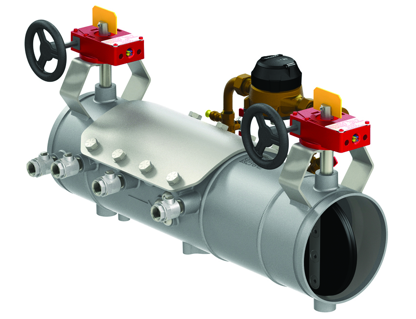
There are six basic types of backflow preventers used to protect cross-connections. They can be classified by whether they are non-testable or testable. These include air gaps, barometric loops, atmospheric and pressure vacuum breakers, dual check valves and dual checks with intermediate atmospheric vents, double check valve assemblies, and reduced pressure principle devices.
The normal operation of a device will include the unavoidable impact from external sediments and debris from water sources. Backflow preventers that are harder to repair and replace are more expensive over time; therefore, the cheapest solution is probably not necessarily the correct solution. Some backflow preventers have modular parts or fewer moving parts that can be replaced with locally available components. Some are selected because they are lightweight and can be installed and more easily replaced without extra plumbing staff.
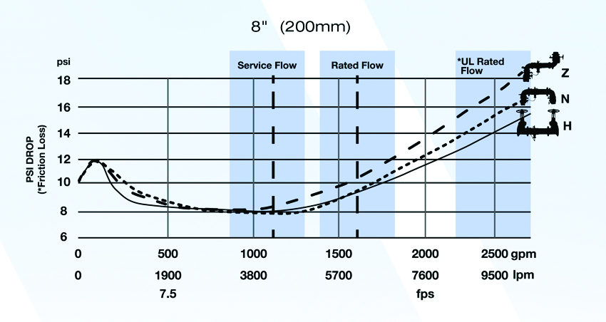
Shown is a performance flow curve.
Flow characteristics may determine the size of the entire plumbing riser system. Although pressure loss is an area of concern for all systems, it is especially critical within a fire prevention system. The engineers will calculate the pressure loss across backflow devices. An incoming water source is not always delivered at a constant pressure and may have many variables. In some cases, a booster pump or larger-diameter piping may need to be installed. Each case and application is unique so copying an “old specification” for a new project can be dangerous.
Selecting Backflow Preventers
Backflow preventers can be classified into two major types: testable versus non-testable devices. These mechanical devices contain check valves designed to allow fluids to flow forward while automatically stopping reverse flow. There can be numerous degrees of hazards of the fluids on the downstream side of backflow preventers, and this will impact the selection of the appropriate device. The specifier will also analyze the size, location, likely failure mode, or the need for constant pressure when selecting a device. Some conditions may require the selection that will allow for a shutoff downstream or meet unique regulatory requirements. The selection of a backflow preventor includes the consideration of the cost, weight, reparability, and maintenance of the device.
Testable backflow preventers are larger devices and usually the most expensive. They are rarely specified for residential containment, though they are often used for isolation of residential lawn sprinkler systems. Most commercial devices are testable and required by regulations to be tested annually and when installed or repaired. The AHJ will determine testing requirements for these devices.
Non-Testable Backflow Prevention Valves
Non-testable backflow prevention valves include the following common types.
Atmospheric vacuum breakers are typically used to isolate an area that poses a health hazards.
Atmospheric Vacuum Breaker (AVB) ASSE 1001
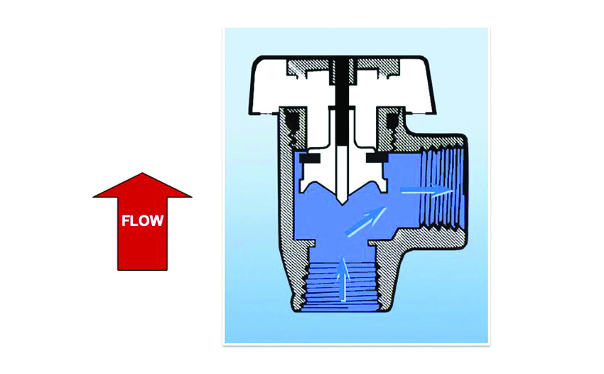
Atmospheric vacuum breakers (AVBs) are typically used to isolate an area that poses health hazards. Typical installations include AVBs on lawn sprinklers, parlor sinks, dishwashers, washing machines, and industrial process tanks. They only protect backsiphonage events, preventing the backflow of non-potable liquids into drinking water.
The breaker is sealed by a float that is raised by the pressure of the drinking water on the upstream side of the valve. In the event of backsiphonage, negative pressure will suck the float down, open the vent, and break the vacuum. At this point, the line will suck in air rather than the potentially contaminated water downstream. Engineers will not specify an AVB when continuous pressure is required. Concerns are that, after a time, the vent float will fail and get stuck in the up position. For this reason, downstream shutoffs are incompatible with this system. They must also be installed a minimum of 6 inches above the flood level rim of the application served unless deck/equipment mounted.
Hose bib vacuum breakers are designed for isolation protection against backsiphonage. These devices are appropriate for use when there is a health hazard.
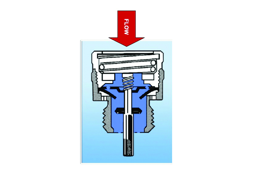
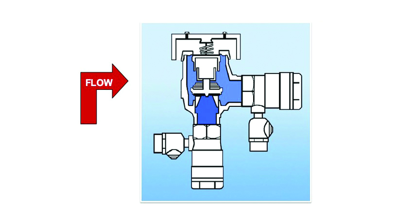
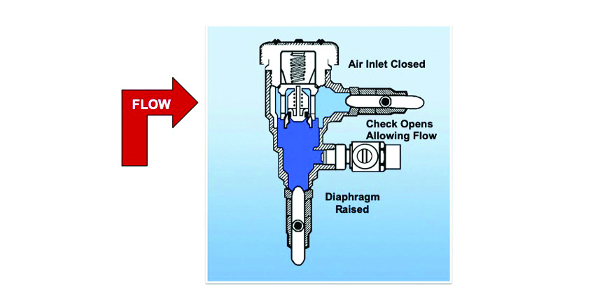
Hose Bib Vacuum Breaker (HBVB) ASSE 1011
Hose bib vacuum breakers (HBVBs) are designed for isolation protection against backsiphonage. These devices are appropriate for use when there is a health hazard. Hoses are the number-one source of unprotected cross-connection in America. There are many case studies of water contamination through unprotected hose bibs. Hoses can be connected to almost anything and should not be subjected to continuous pressure. These common devices contain a check valve and a diaphragm that is pushed against air vents when pressurized and will recede and open the air vents, breaking the vacuum in the case of backsiphonage conditions.
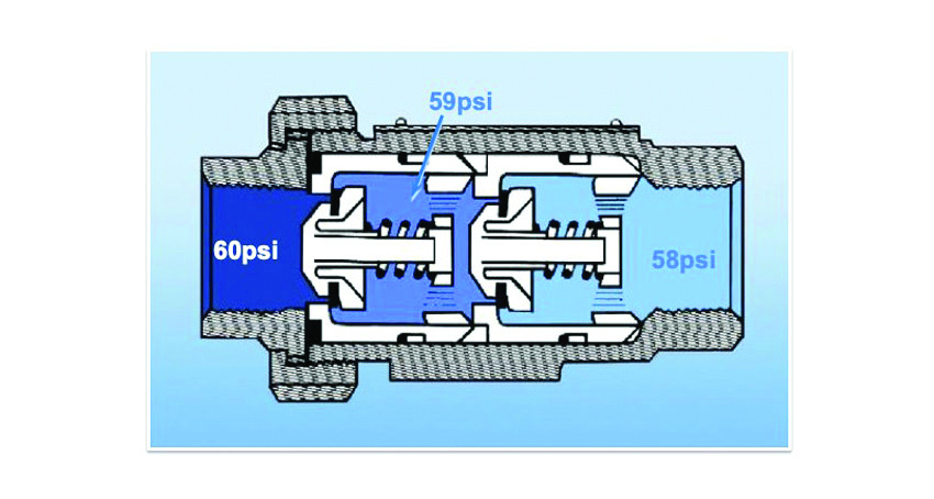
Dual check valves are specified for residential projects. They are often placed after the water meter.
Dual Check Valve (DuC) ASSE1024
Dual check valves (DuCs) are typically specified for residential projects. They are often placed after the water meter. They are rated for backsiphonage and backpressure, as well as continuous pressure, but cannot be used when there is an application that requires defense against health hazards.
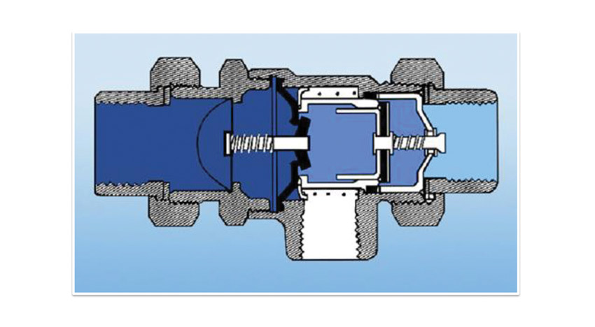
These devices are a combination of dual checks and vacuum breakers. ASSE 1012 is used for non-health hazard conditions, and ASSE1052 and 1035 are both rated to be used when a health hazard is present.
Dual Checks with Atmospheric Vents (VDuC) ASSE 1012/1052/1035
These devices are a combination of dual checks and vacuum breakers. ASSE 1012 is used for non-health hazard, full backpressure, continuous pressure applications, and most commonly used as a residential boiler feed valve. ASSE 1052 and 1035 are both rated to be used for health hazard conditions. Like HBVBs, ASSE 1052 and 1035 devices are only rated for low backpressure and cannot be subjected to continuous pressure. ASSE 1052 is a hose connection backflow preventer that works very similarly to a hose bib vacuum breaker. ASSE 1035 is a laboratory faucet vacuum breaker similar to the hose-connection vented dual check, but with a higher temperature rating and lab faucet connections. These devices will have occasional water discharge and installation should specify drainage.
These carbonator valves are dual checks, and dual checks with atmospheric vents, respectively, but they are made specifically for carbonated beverage dispensers.
Carbonated Beverage Backflow Preventer (CBBP) ASSE 1032/1022
These carbonator valves are dual checks, and dual checks with atmospheric vents, respectively, but they are made specifically for carbonated beverage dispensers. The danger to the plumbing system is that when you mix carbon dioxide with water to make carbonated water (for example, at a soda fountain), you also form carbonic acid. This acid will leach copper out of pipes if it backs up into the plumbing system, and there are several case studies where this exact situation has sent people to the hospital.
Testable Backflow Preventers
Testable backflow prevention valves include the following common types.
Pressure vacuum breakers are commonly used on residential sprinkler systems.
Pressure Vacuum Breaker (PVB) ASSE 1020
Like an atmospheric vacuum breaker, these are for backsiphonage only and appropriate for health hazard applications. They are designed for applications that have continuous pressure and therefore can have shutoffs downstream. These are most commonly specified for residential sprinkler systems since there can be zone valves downstream. These devices will occasionally discharge water. They must be installed a minimum of 12 inches above the flood level rim or highest outlet of the downstream piping, such as the highest sprinkler head in an irrigation system.
Primarily installed indoors, a spill-resistant vacuum breaker prevents the hazardous release of chemicals.
Spill-Resistant Vacuum Breaker (SVB) ASSE 1056
A spill-resistant vacuum breaker operates largely the same way as the PVB and is installed when there is a health hazard present. The SVB has a spill-resistant feature that closes the vent prior to the check opening. These can be used indoors and prevent the occasional discharge of water. They are often used in chemical dispensers and must also be mounted above downstream outlets.
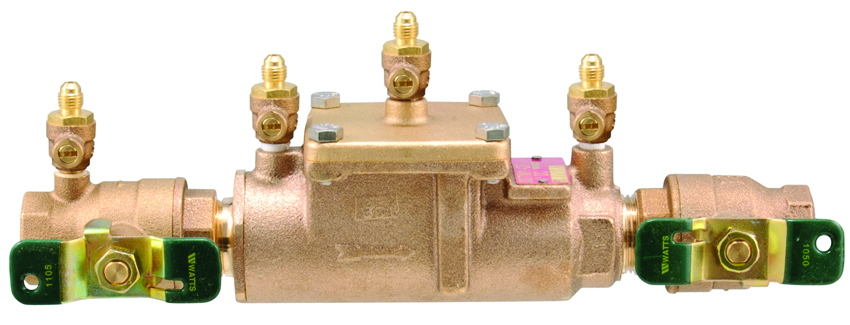
Double check valve assemblies are designed for use in non-health hazard applications.
Double Check Valve Assembly (DC) ASSE 1015
Double check valve assemblies are larger devices typically designed for 1⁄2-inch to 10-inch outlet connections. They are used for containment or isolation of non-health hazard applications or pollutants. They are able to handle backpressure, backsiphonage, and continuous pressure situations. They can be installed horizontally or vertically with the flow upward. These devices are rated assemblies with shutoffs on either side. These shutoffs are part of the assembly and should not be removed unless they are replaced with another manufacturer-approved shutoff. Code regulates the orientation of the assembly and assembly components.
These assemblies are designed for use in non-health hazard cross-connections and continuous pressure applications subject to backpressure or backsiphonage incidents, such as lawn sprinklers, fire sprinkler lines, commercial pools, tanks and vats, and food cookers. Testing will verify that the assembly is working but does not provide a mechanism for early notification of failure.
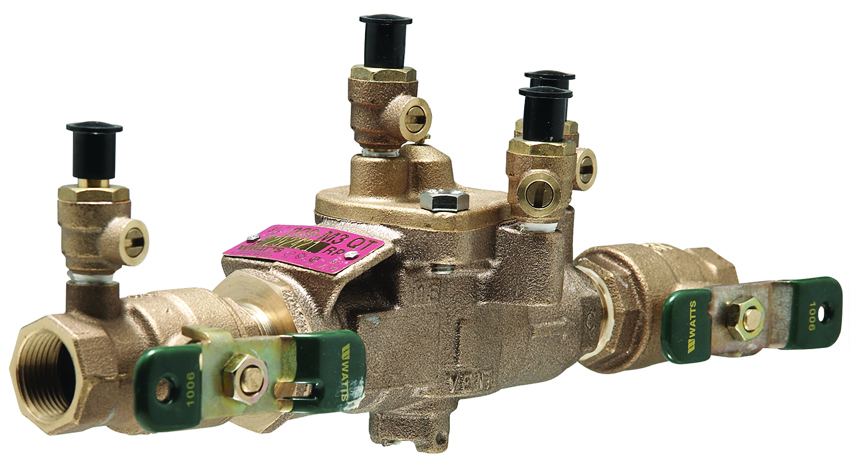
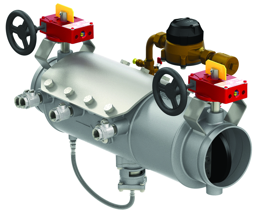
Reduced pressure zone assemblies (RPZAs) provide the highest possible degree of protection from hazards caused by cross-connection failures. In catastrophic events, an RPZA will discharge a lot of water and require a design location that will accommodate this potential for water damage.
Reduced Pressure Zone Assembly (RPZA) ASSE 1013
Reduced pressure zone assemblies (RPZAs) provide the highest possible degree of protection from hazards caused by cross-connection failures. This is a more complex assembly and will occasionally discharge water. An RPZA must be installed a minimum of 12 inches above grade and typically cannot be installed vertically. In catastrophic events, an RPZ will discharge a large amount of water and require a location that will accommodate this potential for flooding.
Double check detector assemblies provide a bypass on an unmetered sprinkler system and are used with non-hazard conditions.
Double Check Detector Assemblies (DCDAs) ASSE1048
Double check detector assemblies (DCDAs) are similar to double checks but have a bypass that monitors unauthorized water usage or leaks. These are typically installed on unmetered fire sprinkler system connections. They detect the unauthorized diversion of water. A bypass around the device is designed to identify the first 2 gallons per minute of flow to alert the water authority to a problem. The bypass must contain a backflow preventer with the same level of protection as the device it is bypassing, typically another double check assembly. They are used with non-hazard conditions.
Reduced pressure detector assemblies are similar to double check detector assemblies. They are installed in applications with potential health hazards.
Reduced Pressure Detector Assembly (RPDA) ASSE1047
A reduced pressure detector assembly is an RPZ assembly that also monitors unauthorized water usage or leaks. They are used in high-hazard fire-protection applications and function in much the same way that a DCDA does, but instead of a double check in the bypass, they are constructed with a reduced pressure zone assembly. They are installed in applications with potential health hazards.
Detecting a Discharge
Reduced pressure assemblies are designed with a unique relief valve that responds to differential pressure changes. The normal operation of an RPZ is shown in this short online video example. The second video demonstrates what occurs when debris clogs the first check, causing a backflow event.
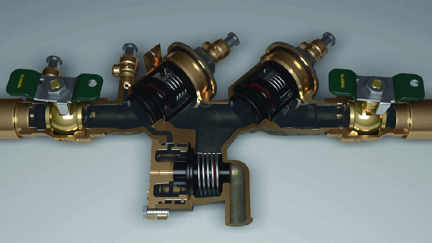
Shown is a normal RPZA flow example.
Shown is an RPZA backflow example demonstrating a fouled first check example.
In this example, debris is stuck in the first check when the water is flowing. A fouled second check is less common but can also potentially cause the relief valve to open if there is backpressure in the system. The opening of the relief valve releases water to drain potentially contaminated water rather than allow it to enter the potable water supply. The size of the debris will dictate the size of the discharge.
Something as small as a grain of sand, water sediment, or pieces of tape, or construction dust can cause an RPZ relief valve to open. A large rock can cause high flow and even the release of a constant stream of water. The discharge provides a visual and physical indication of failure and prevents contamination of the drinking water by breaking the cross-connection.
RPZAs are designed to release water when the lines are clogged or when a valve is frozen due to line pressure changes and weather incidents causing extreme flooding. Particularly in southern climates, these systems may be installed outside. With changing climate conditions, more of these systems may need to be protected from freezing.
Design Tips to Avoid Failures
The following list of best practices will lead the design professionals to successful cross-connection systems. The project manager will provide guidance throughout schematic design (SD), design development (DD) construction documentation (CD), construction administration (CA), and commissioning. Providing a strong review and analysis of cross-connection controls is critical to the safety and resiliency of the complete water system.
- Meet with the mechanical engineer (ME) to review equipment requirements and locations for non-hazardous and hazardous applications that require appropriate backflow prevention systems. (SD, DD)
- Contact the AHJ and continue to monitor and review all permitting authorities (federal, state, and local) to plan permit scheduling. (SD, DD, CD, CA)
- Verify that all systems meet regulatory requirements, particularly for local jurisdiction. (SD, CD)
- Review construction documents for locations and orientation of all check valve equipment for accessibility for maintenance, replacement, and annual testing. (CD)
- Conduct a value survey for all systems and consider future maintenance and repairs. Review the potential for whether a smaller and lighter units or assemblies should be installed. (CD)
- Review with construction team the protection of piping and fixtures in storage or on site. Warranties do not cover poor installation and the improper flushing of plumbing lines. This can cause debris to clog valves. The primary cause of early installation failures is that lines are improperly flushed and debris is caught in the first check valve. Chunks of concrete, gloves, and animals have been found in RPZAs, and instead of removing the valve for return to the manufacturer, a qualified professional can open it up to repair the system. (CA)
- Provide proper commissioning and test for the potential for line failures including construction debris, improper flushing, change in locations for hazardous applications, line pressure, freeze protection, etc. Require maintenance and repair manuals for all applicable systems. Manuals should include repair and replacement code and permitting requirements as well as schedules for testing. (Commissioning)
- Require certified and qualified technicians for replacements and repairs to backflow prevention equipment.
Typical cross-connection controls are simple mechanical systems based on the pressure dynamics of flow control. Most of these mechanisms have not dramatically changed since the last century. However, a few innovations may be soon coming to market. Among these are digital controls that may be able to diagnose leak conditions at earlier stages. These systems may be able to be hooked up to automatic building management. Smaller, lighter, and modular components are now on the market. These new products will not only impact the installation of backflow preventers but also change the ongoing maintenance, replacement, and repair of cross-connection controls.
Protecting public health, safety, and welfare through a safe water supply depends on understanding cross-connection control systems. Professionals, who understand the basics of backflow prevention are better able to protect drinking water, conserve water resources, and provide resilience to all buildings.
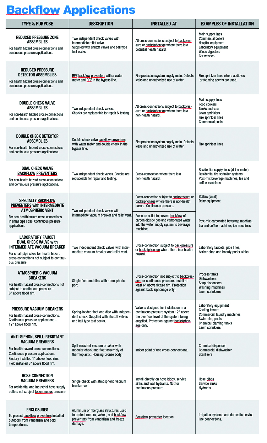
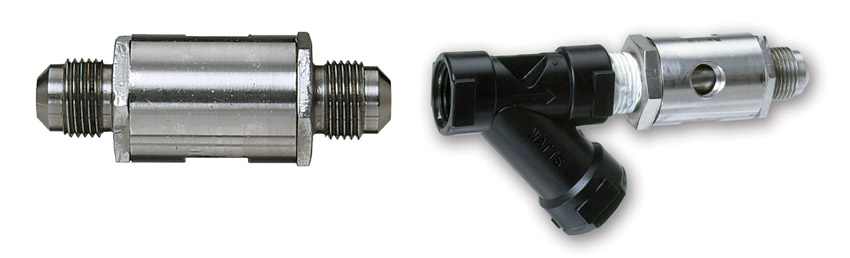
Shown are backflow applications.
End Notes
1Water Quality Standards Handbook. U.S. Environmental Protection Agency. Web. 20 February 2020.
2Potential Contamination Due to Cross-Connections and Backflow and the Associated Health Risks. U.S. Environmental Protection Agency. Web. 22 February 2020.
3Cross Connection Control Manual. U.S. Environmental Protection Agency. Web. 17 February 2020.
4Plumbing Code 2015 of Utah. UpCodes. Web. 21 February 2020.
5Manual of Water Supply Practices: Backflow Prevention and Cross-Connection Control Recommended Practices. American Water Works Association. Web. 19 February 2020.
6“Water Turned Into Wine.” Robb Report. Web. 9 March 2020.
7,8 Womack, Kim. “Back-Flow Incident Leads to Discontinuation of Tap Water Usage Citywide Until Further Notice.” City of Corpus Christi News Room. 14 December 2016. Web. 9 March 2020.
Celeste Allen Novak is an architect and author whose Michigan practice focuses on sustainable and universal design. www.linkedin.com/in/celestenovak