This CE Center article is no longer eligible for receiving credits.
Wind- and Seismic Force-Resisting Systems
ASCE 7 recognizes several wood-frame seismic- and wind force-resisting systems. These include sheathed wood-frame diaphragms and shear walls and now, CLT diaphragms and shear walls.
Light wood-frame diaphragms and shear walls include 1) light wood-frame walls with wood structural panels rated for shear resistance; and 2) light wood-frame walls with structural panels made from other materials, including particleboard, structural fiberboard, gypsum wallboard, gypsum base for veneer plaster, water-resistant gypsum backing board, gypsum sheathing board, gypsum lath and plaster, and Portland cement plaster. SDPWS also allows wood-frame shear walls sheathed with wood structural panels to be designed to simultaneously resist shear and uplift from wind forces. The design requirements for wood-frame diaphragms and shear walls used in these systems are contained in Chapter 4 of the 2021 SDPWS.
The increasing popularity of mass timber structures and construction products such as CLT prompted an examination of how these materials, and the resulting taller buildings, may perform during natural disasters. However, until the release of the 2021 SDPWS, use of CLT as diaphragms or shear walls to resist wind and seismic forces had not been codified. The 2021 SDPWS contains new design provisions for CLT diaphragms and CLT shear walls. CLT diaphragm provisions are found in Section 4.5 and CLT shear wall provisions are found in Section 4.6 and Appendix B.
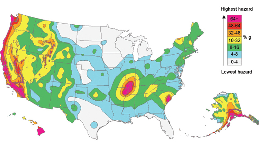
Figure 2: This USGS earthquake hazard map shows peak ground accelerations for a firm rock site having a 2 percent probability of being exceeded in 50 years.
Risk Category
Before considering provisions specific to wind or seismic hazards, identify the risk category of the building or structure as defined by the IBC. Risk categories are assigned to buildings to account for consequences and risks to human life (building occupants) in the event of a building failure. Risk categories are used to classify buildings and structures based on their importance and take into consideration occupancy, risk to human life, and societal need of the building or structure to function during and following an extreme event. For example, hospitals and other essential facilities are assigned the highest risk category (Risk Category IV) and therefore must meet more stringent design criteria. Detailed descriptions of buildings and structures associated with Risk Categories I, II, III, and IV are provided in 2021 IBC Table 1604.5.
Seismic Design and Wood
Earthquakes are an unpredictable fact of life in some regions in North America, particularly along the West Coast. The map in Figure 2, prepared by the United States Geological Survey (USGS), illustrates the seismic hazard for the entire country, with areas of greatest risk shown in red.
Although developers of building codes accept that some nonstructural and structural damage will occur, they seek to limit the likelihood of structural collapse and to ensure the superior performance of essential facilities such as hospitals and fire stations. These performance expectations are set in recognition of the fact that it is not economically feasible to prevent all damage in all buildings when designing for infrequent, large-magnitude earthquakes.
Earthquakes cannot be prevented, but proper design and construction—based on compliance with building code requirements—can reduce their negative impacts.
Referencing ASCE 7, building codes address the probability and severity of earthquakes by providing design requirements based on the site-specific seismic hazard and the building’s risk category.
ASCE 7 and model building codes such as the IBC provide maps that identify seismic hazards. Created in cooperation with the USGS and FEMA, these maps are updated regularly and assist engineers in designing buildings, bridges, highways, and utilities that will withstand seismic shaking.
Calculating Seismic Design Forces
The IBC establishes the minimum lateral seismic forces for which buildings must be designed, primarily by reference to ASCE 7-16. Base shear refers to the total horizontal force resisted through a structure’s lateral force-resisting system as the mass of the building accelerates due to ground shaking. The equivalent lateral force (ELF) procedure is the most used procedure for determining base shears. This is particularly true for low-rise, short-period, wood-frame buildings.
Base shear, or V, is proportional to the effective seismic weight of the structure and the seismic hazard at the site. The seismic hazard is represented by several variables: the spectral response acceleration parameter, SDS; response modification coefficient, R; and the importance factor, Ie. Effective seismic weight, or W, includes both dead load plus some live loads as prescribed in Section 12.7.2 of ASCE 7-16.
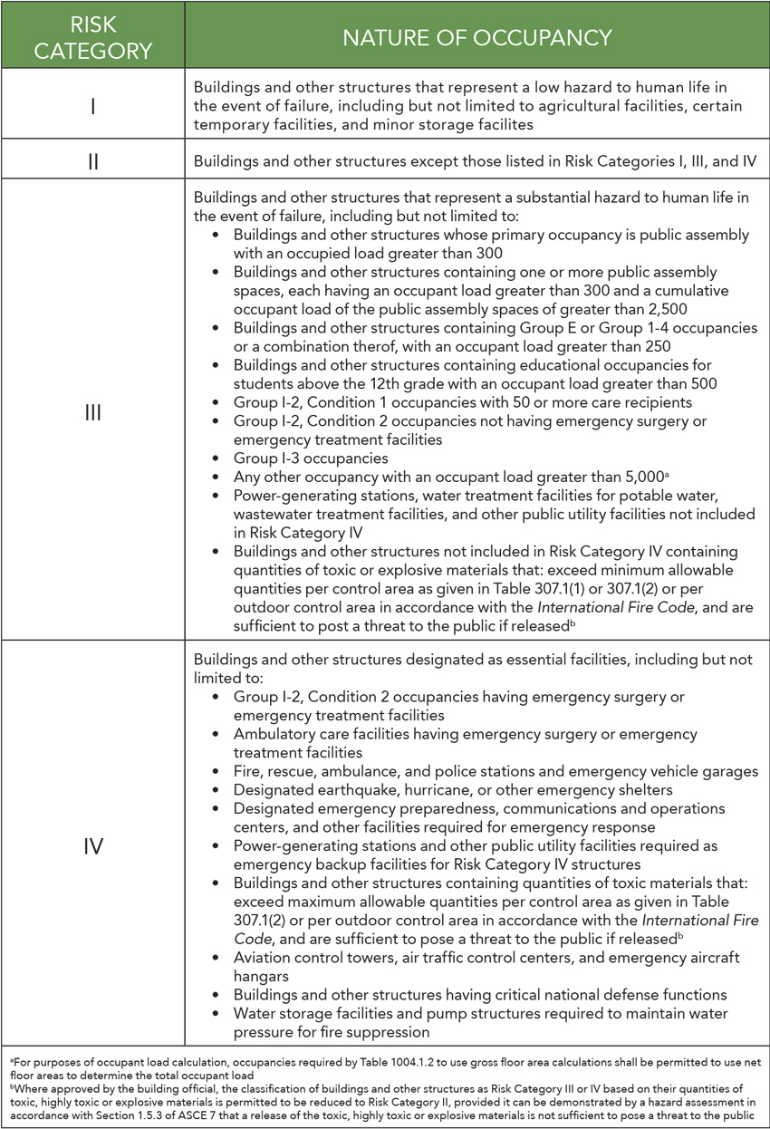
Table 1: Risk categories of the building or structure as defined by the IBC
Resilience is the capacity of a structure or system to withstand and recover quickly from disruptive events, be they natural or human-caused disasters. High winds, hurricanes, and earthquakes are a harsh reality for much of the United States and designing a building to withstand the potentially devastating forces of high winds or seismic events is a challenge an architect or engineer will likely face.
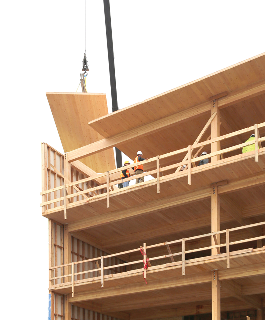
Photo courtesy of LEVER Architecture
Resilience is a key component of building design when addressing both seismic and wind design. Properly designed and constructed wood structures that comply with building code requirements are resilient, performing with minimal damage while protecting occupants during both seismic and high wind events.
Properly designed and constructed wood structures that comply with building code requirements are resilient, performing with minimal damage while protecting occupants during both seismic and high wind events.
For example, safe rooms constructed with wood and following prescriptive plans set forth by the Federal Emergency Management Agency (FEMA) are designed to withstand a 250-mph wind force and can pass a 100-mph “missile” impact test.1 Such rooms are meant to provide refuge for occupants during extreme weather events.
In another test, a seven-story, wood-frame building constructed at Japan's Hyogo Earthquake Engineering Research Center showed only minor signs of damage after a simulated quake that reached 7.5 on the Richter scale.2
Resilience is a key component of building design and should be addressed in every new project.
This continuing education course offers an overview of the benefits of light wood-frame construction, followed by a summary of key considerations in both seismic and wind design. The second half of the course focuses on issues and code provisions relevant to seismic- and wind-resistive design in light wood-frame construction, specifically compliance with the 2021 International Building Code (IBC) and the American Society of Civil Engineers/Structural Engineering Institute Minimum Design Loads for Buildings and Other Structures (ASCE 7-16).
Designing for Continuous Load Path
Any discussion of designing for seismic and high wind events should begin with an overview of how various forces are transferred within a structure. Engineers and architects use the term “load path” to describe how forces flow through a building's structure to the final point of resistance at the foundation. A continuous load path is like a chain that ties building elements together from the roof to the foundation, offering seamless transfer of load.
Design forces, including snow loads, wind, or an earthquake, are specified in the building code and referenced standards, and the building must be designed to withstand those forces without failure. For a structure to remain stable, a load applied at any point must have a path allowing transfer of the load through each building part, down to the building foundation and supporting soils.
The concept of a load path can be seen in the exploded diagram of a house in Figure 1, taken from FEMA’s publication, “Homebuilders’ Guide to Earthquake Resistant Design and Construction” (FEMA 232).3 As this example shows, load transfer occurs via the roof-ceiling system and its connections to the second-story bracing wall system; through the second-story bracing wall system and its connections to the floor-ceiling system; by the floor-ceiling system and its connections to the first-floor bracing wall system; through the first-story bracing wall system and its connections to the foundation; and from the foundation to the supporting soil.
How Wood Enables Resilience
The ability of a properly designed and maintained wood building to provide occupant safety in extreme conditions can be attributed to several factors:
- Robust design criteria in applicable codes and standards: Codes and standards governing the design and construction of wood-frame buildings have evolved based on experience from prior earthquakes, hurricanes, wind loads, and related research.
- Codes also prescribe minimum fastening requirements for the interconnection of wood framing members—requirements that are unique to wood-frame construction and beneficial to a building’s performance.
- Ductile connections: Multiple nailed connections in framing members, shear walls, and diaphragms of wood-frame construction exhibit ductile behavior—the ability to yield and displace without sudden brittle fracture.
- Redundant load paths: Wood-frame buildings tend to be comprised of repetitive framing attached with numerous fasteners and connectors, which provide multiple, and often redundant, load paths for resistance to forces. Plywood or oriented strand board (OSB) diaphragms and shear walls have proven to be exceptionally resistant to these forces.
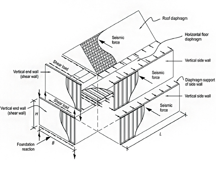
Figure 1: Load transfer between components in a building
Resilient Design and Today’s Codes
Building codes are intended to protect occupants and first responders and, to a lesser extent, limit property damage. By considering potential hazards together with the building’s intended use, they establish a minimum level of safety for all buildings, regardless of the building material used.
The 2021 IBC references ASCE 7-16, “Minimum Design Loads and Associated Criteria for Buildings and Other Structures.” This document is used to determine dead, live, soil, flood, tsunami, snow, rain, atmospheric ice, earthquake, and wind loads, and any combination thereof for general structural design. Minimum design loads are established to ensure that every building is designed to withstand loads that have a certain probability of occurring in its lifetime.
For the wind and seismic hazards, codes address the probability and severity of wind events and earthquakes by providing design requirements that are specific to regional risks. Codes are also intended to ensure the superior performance of essential facilities, such as hospitals and fire stations, relative to other structures.
Wind- and Seismic Force-Resisting Systems
ASCE 7 recognizes several wood-frame seismic- and wind force-resisting systems. These include sheathed wood-frame diaphragms and shear walls and now, CLT diaphragms and shear walls.
Light wood-frame diaphragms and shear walls include 1) light wood-frame walls with wood structural panels rated for shear resistance; and 2) light wood-frame walls with structural panels made from other materials, including particleboard, structural fiberboard, gypsum wallboard, gypsum base for veneer plaster, water-resistant gypsum backing board, gypsum sheathing board, gypsum lath and plaster, and Portland cement plaster. SDPWS also allows wood-frame shear walls sheathed with wood structural panels to be designed to simultaneously resist shear and uplift from wind forces. The design requirements for wood-frame diaphragms and shear walls used in these systems are contained in Chapter 4 of the 2021 SDPWS.
The increasing popularity of mass timber structures and construction products such as CLT prompted an examination of how these materials, and the resulting taller buildings, may perform during natural disasters. However, until the release of the 2021 SDPWS, use of CLT as diaphragms or shear walls to resist wind and seismic forces had not been codified. The 2021 SDPWS contains new design provisions for CLT diaphragms and CLT shear walls. CLT diaphragm provisions are found in Section 4.5 and CLT shear wall provisions are found in Section 4.6 and Appendix B.
Figure 2: This USGS earthquake hazard map shows peak ground accelerations for a firm rock site having a 2 percent probability of being exceeded in 50 years.
Risk Category
Before considering provisions specific to wind or seismic hazards, identify the risk category of the building or structure as defined by the IBC. Risk categories are assigned to buildings to account for consequences and risks to human life (building occupants) in the event of a building failure. Risk categories are used to classify buildings and structures based on their importance and take into consideration occupancy, risk to human life, and societal need of the building or structure to function during and following an extreme event. For example, hospitals and other essential facilities are assigned the highest risk category (Risk Category IV) and therefore must meet more stringent design criteria. Detailed descriptions of buildings and structures associated with Risk Categories I, II, III, and IV are provided in 2021 IBC Table 1604.5.
Seismic Design and Wood
Earthquakes are an unpredictable fact of life in some regions in North America, particularly along the West Coast. The map in Figure 2, prepared by the United States Geological Survey (USGS), illustrates the seismic hazard for the entire country, with areas of greatest risk shown in red.
Although developers of building codes accept that some nonstructural and structural damage will occur, they seek to limit the likelihood of structural collapse and to ensure the superior performance of essential facilities such as hospitals and fire stations. These performance expectations are set in recognition of the fact that it is not economically feasible to prevent all damage in all buildings when designing for infrequent, large-magnitude earthquakes.
Earthquakes cannot be prevented, but proper design and construction—based on compliance with building code requirements—can reduce their negative impacts.
Referencing ASCE 7, building codes address the probability and severity of earthquakes by providing design requirements based on the site-specific seismic hazard and the building’s risk category.
ASCE 7 and model building codes such as the IBC provide maps that identify seismic hazards. Created in cooperation with the USGS and FEMA, these maps are updated regularly and assist engineers in designing buildings, bridges, highways, and utilities that will withstand seismic shaking.
Calculating Seismic Design Forces
The IBC establishes the minimum lateral seismic forces for which buildings must be designed, primarily by reference to ASCE 7-16. Base shear refers to the total horizontal force resisted through a structure’s lateral force-resisting system as the mass of the building accelerates due to ground shaking. The equivalent lateral force (ELF) procedure is the most used procedure for determining base shears. This is particularly true for low-rise, short-period, wood-frame buildings.
Base shear, or V, is proportional to the effective seismic weight of the structure and the seismic hazard at the site. The seismic hazard is represented by several variables: the spectral response acceleration parameter, SDS; response modification coefficient, R; and the importance factor, Ie. Effective seismic weight, or W, includes both dead load plus some live loads as prescribed in Section 12.7.2 of ASCE 7-16.
Table 1: Risk categories of the building or structure as defined by the IBC
Seismic Design Category
Once you’ve determined the building’s risk category, the next step is to determine the seismic design category (SDC). SDC is determined based on several factors:
- Soil properties at the site, or site class, classified as A, B, C, D, E, or F: Site class A is associated with the presence of hard rock. Site class F is associated with peats and/or highly organic clays, very high plasticity clays and very thick, soft/medium stiff clays
- Mapped values of the seismic hazard
- Risk category of the structure
SDCs range from A to F, with A representing the lowest risk and F the highest. The SDC is used to determine permitted seismic force-resisting systems and structural height limitations. It also determines the applicability of special requirements associated with structural redundancy and structural irregularities in the building system.
SDC A represents a very low seismic hazard for which there are no seismic-specific limits (NL) on structural height, system type, structural redundancy, or structural irregularities. Structures located in this category are not subject to design forces determined in accordance with the ELF. Beginning with SDC B, seismic forces in accordance with ELF are applicable and consideration must be given to special requirements for structural irregularities. Special requirements and limitations become increasingly stringent in SDC C and higher. As can be seen in Table 2, as seismic design category increases, structural height limitations apply as well as limitations on the use of some lateral force-resisting systems.
Calculating SDC for Short-Period Structures
For short-period structures, such as most wood-frame structures, ASCE 7 allows determination of the seismic design category based on value of SDS (design spectral response acceleration) and risk category alone (see Table 3), provided alternative criteria are met for structure period and diaphragm flexibility and the site’s mapped spectral response acceleration period value (S1) is less than 0.75.
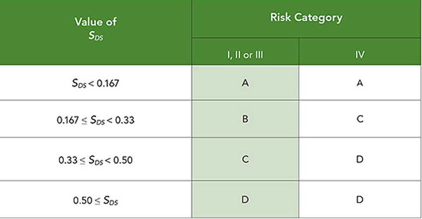
Table 2: Wood-frame seismic force-resisting systems, extracted from ASCE 7-16 Table 12.2-1
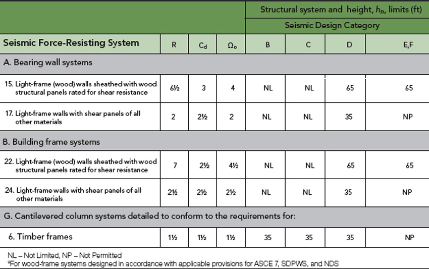
Table 3: Seismic design category based on short-period response acceleration parameter, adapted from ASCE 7-10, Table 11.6-1
Structural Redundancy
Separate from inherent redundancies present in typical wood construction, the code encourages a redundant layout of seismic force-resisting systems throughout the building. The redundancy factor, ρ, which is either 1.0 or 1.3, is applied to the seismic design forces based on lateral force-resisting system configuration. In SDC B and C, the redundancy factor equals 1.0. For wood-frame shear walls in higher seismic design categories, use of a redundancy factor equal to 1.0 can often be accomplished for plans that have a regular layout and where lateral resistance is provided on all sides of the building perimeter by shear walls with aspect ratios (height-to-length) of 1.0 or less, or, for cases where the aspect ratio of individual shear walls is greater than 1.0, the total length of light-frame shear walls equals or exceeds the story height.
Special Design Conditions: Anchorage of Concrete or Masonry Structural Walls to Wood Diaphragms
Requirements for anchorage of concrete or masonry structural walls to wood diaphragms, found in both ASCE 7 and SDPWS, were developed to address instances where these structural walls became detached from supporting roofs, resulting in collapse of walls and supported bays of framing. The intent is to prevent the diaphragm from tearing apart during strong shaking by requiring transfer of wall anchorage forces across the complete depth of the diaphragm.
Minimum out-of-plane wall anchorage design forces are provided in ASCE 7 Section 12.11.2. Additional requirements, applicable in SDCs C, D, E, and F, are provided in Section 12.11.2.2. Provisions include the use of continuous ties between diaphragm chords to distribute wall anchorage forces into the diaphragm and permitting the use of subdiaphragms to transfer anchorage forces to main continuous cross-ties. Restrictions exist on the use of toe-nailed connections and nails subject to withdrawal, and on framing loaded in cross-grain bending or cross-grain tension. Special detailing provisions for wood diaphragms consistent with those in ASCE 7 were first added to 2015 SDPWS in Section 4.1.5.
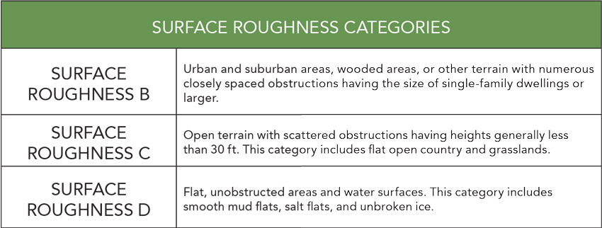
Table 4: Surface Roughness Categories as defined by the IBC
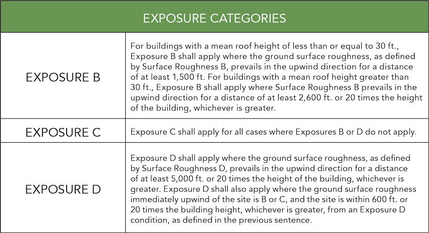
Table 5: Exposure Categories as defined by the IBC
Wind Design and Wood
Many regions of the United States experience high winds, with the accompanying threat of wind-related damage to buildings. According to the Insurance Institute for Business and Home Safety (IBHS), high winds cause billions of dollars of property loss each year.8 However, damage from wind can be minimized through engineered design which strengthens buildings against wind forces. As with the seismic provisions, codes and standards governing the design and construction of wood-frame buildings have evolved based on field data from prior wind events and related research.
Each building, with its own unique characteristics and site conditions, reacts differently to wind loads. Many complex and interrelated issues must be addressed before a building can be truly considered wind-resistant.
Structural Wind Loading
The wind loading requirements in the IBC are determined primarily through reference to ASCE 7-16. The minimum design requirements for wind loads are intended to ensure that every building and structure has sufficient strength to resist these loads without stressing any of its structural elements beyond the material strengths prescribed in the code. The code emphasizes that the loads prescribed in Chapter 16 are minimum loads; in most conditions, the use of these loads will result in a safe building. For this reason, it is important to ensure that wind loads are properly determined. The commentary that accompanies ASCE 7-16 is a good source for additional information, as it outlines conditions which may result in higher loading.
Wind Loads on Buildings
Buildings and structures are designed and constructed to resist wind loads, or wind pressure, as opposed to wind speeds. Wind speed, although a significant contributor, is only one of several factors that impact wind loads acting on a building. Other factors that affect the calculated design wind loads (pounds per square foot, or psf) include:
- Combined gust factor and external pressure coefficients (GCpf)
- Combined gust factor and internal pressure coefficients (GCpi)
- Design velocity pressure
Design velocity pressure varies depending on several factors, including mapped wind speed, exposure category, topographic effects, wind directionality, elevation factor, and other specific building characteristics. All of these are covered in the following sections.
Mapped Wind Speeds and Risk Category
Mapped wind speeds are based on the probability of winds attaining certain speeds per geographic area. They are developed from an analysis of wind speed data collected during severe wind events and assuming a set of reference conditions. Current wind speed maps include a more comprehensive analysis of wind speeds for both coastal and non-coastal areas than was previously available. The wind maps in ASCE 7-16 vary substantially from previous versions. In most parts of the country, particularly in the West, winds speeds have decreased.
The risk categories introduced earlier also apply when designing for wind loads. Mapped wind speeds for Risk Category III and IV buildings, for which the potential consequences to human life and economic impact are greatest, are higher than mapped wind speeds for Risk Category II buildings. The ultimate design wind speed (Vult, in miles per hour) for the establishment of wind loads is determined using wind speed maps contained in three IBC Figures: Figure 1609.3(1) for Risk Category II buildings, Figure 1609.3(2) for Risk Category III buildings, figure 1609.3(3) for Risk Category IV buildings, and Figure 1609.3(4) for Risk Category I buildings.
Surface Roughness and Exposure Categories
One of the basic decisions in the design of wind-resistant buildings is determination of exposure category based on the “surface roughness” of nearby terrain. Surface roughness depends on natural topography, vegetation, and existing built structures. Obstructions upwind of the building site can exert a drag force on wind, slowing the flow of air close to the surface of nearby terrain (see Table 4).
For each wind direction considered, an exposure category that reflects the surface irregularities of the terrain must be determined for the site at which the building or structure is to be constructed (see Table 5).
Exposure B is the most common exposure category in the country and is often the default exposure category. However, it is important to recognize that exposure category varies based on conditions at the site and that buildings are often sited on properties which fall under Exposure C and D, with attendant higher wind loading.
Topographic Effects
Abrupt changes in the landscape can affect wind speeds. For this reason, topographic effects are accounted for when calculating wind loads using the topographic factor, or Kzt. Kzt considers the wind “speed-up” effects that occur when wind encounters an isolated hill, ridge, or escarpment.
Wind Directionality
For most wood-frame buildings with wind loads determined in accordance with ASCE 7 load combinations, the effect of wind directionality is accounted for by use of a wind directionality factor. This load reduction factor, called Kd, accounts for two effects: “(1) the reduced probability of maximum winds coming from any given direction and (2) the reduced probability of the maximum pressure coefficient occurring for any given wind direction.” ASCE 7-16 includes a table (Table 26.6-1) which displays the wind directionality factors to be used for each structure type.
Elevation Factor
A new elevation factor has been added in ASCE 7-16 that accounts for changes in air density at elevations above mean sea level. The revised standard includes a table of factors for elevations up to 6000 feet and a formula that can be used to calculate the factor for any elevation.
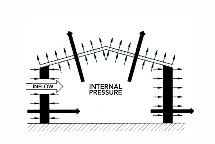
Figure 3: Effect of openings in a partially enclosed building, courtesy of Florida Building Code Commentary
Effect of Openings on Internal Pressure Coefficients
When wind encounters a building, the airflow changes direction and produces several varying effects. Exterior walls and other vertical surfaces facing the wind (windward side) and perpendicular to its path are subjected to positive pressures (loads). Wind continues to flow over and around the building, resulting in suction or negative pressures (loads) on sidewalls, the leeward wall and, depending on geometry, the roof. Wind pressures on a roof vary based on roof slope and location on the roof, with greatest wind pressures occurring at roof edges.
Openings in the building envelope can significantly affect the wind pressures imposed on building elements. Depending on the location and size of openings with respect to wind direction and building porosity, external and internal pressures can act in the same direction to produce higher forces on the walls and roof.
An example of this effect of openings is illustrated in Figure 3. Here, pressures occur on both exterior and interior building surfaces because of a large opening in the windward wall. As this scenario demonstrates, wind enters the building, exerting positive pressures against all interior surfaces. This opening has the net effect of producing high internal pressures that act in the same direction as the external pressures on the roof and leeward walls, adding to the overall pressures on these building elements.
Windows and doors are not considered openings if they are likely to be closed during a design storm event. Therefore, at a minimum, windows and doors need to be rated to resist the positive and negative design wind pressures.
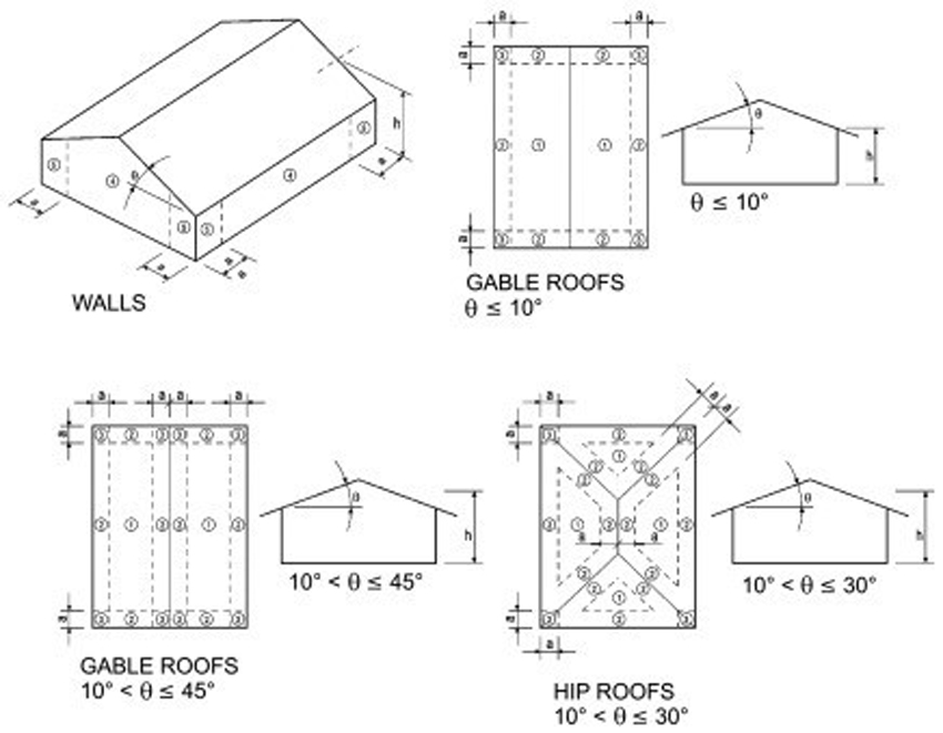
Figure 4: Roof and wall-sheathing zones for wind design, courtesy of Florida Building Code Commentary
External Pressure Coefficients
ASCE 7-16 categorizes wind loads according to the building systems they impact. Main wind force-resisting system (MWFRS) wind loads act on the frame and foundation of a building.
Components and cladding (C&C) wind loads act on cladding elements such as shingles, siding, and windows. Loads are calculated differently for each.
For the design of wood-frame buildings 60 feet in height or less, the “envelope procedure” is the most used method for determining MWFRS loads. External pressure coefficients from the envelope procedure have been developed to represent critical loads on the main structural elements, which are “enveloped” to reflect induced actions on a building from various wind directions for diverse building geometries, roof heights, and roof slopes.
As per ASCE 7, the MWFRS is “an assemblage of structural elements assigned to provide support and stability for the overall structure … [that] generally receives wind load from more than one surface.” Examples of MWFRS elements include roof trusses, roof and floor diaphragms, and shear walls. Individual elements of the MWFRS may also be subject to C&C load requirements. These include sheathing, cladding, wall studs, individual roof rafters and elements of a roof truss, and short-span trusses resisting wind loads from cladding.
External pressure coefficients for C&C represent peak pressures which occur over specific areas on the building’s exterior surface. Localized negative pressures associated with C&C loads almost always control design of exterior sheathing and cladding elements, including wall sheathing, wall cladding, roof sheathing, roof cladding, and the attachment of the sheathing and cladding to the building's structural frame.
Increased Pressure at Edge Zones
The greatest wind pressures acting on a building are negative pressures (suction), and the locations of the greatest suction pressures occur at wall and roof edge zones, as illustrated in Figure 4. Edge zones at wall corners, roof ridge, and roof perimeter represent locations of potentially high suction forces relative to the central portions of the wall or roof. The extent of increase in suction forces for roofs depends on roof geometry, but increases of two or more times the negative pressures associated with central wall area are possible.
For roof sheathing and roof sheathing attachment, the increase in forces between edge zones and interior zones is larger than that observed for walls. While wood structural panel sheathing of consistent grade and thickness is used over the length of the roof, two fastening schedules are often specified.
One fastening schedule is for roof areas outside of edge zones; fasteners here are spaced farther apart. A second fastening schedule is for higher wind pressure roof areas within the edge zones; fasteners here are more closely spaced. The roof sheathing pressures developed from the external pressure coefficients in ASCE 7-16 are higher than in previous versions of ASCE, and thus require more attention to nailing patterns and to nail types and sizes. In some cases, Roof Sheathing Ring Shank nails, which have higher withdrawal design values than smooth shank nails, are required for attachment of roof sheathing to roof framing for resistance to high wind uplift forces.
The withdrawal design values for Roof Sheathing Ring Shank Nails (RSRN) are generally 1.5 to 2 times greater than those for smooth shank nails. When using Roof Sheathing Ring Shank Nails, care should be taken to ensure that the nails are in fact RSRN nails meeting ASTM F1667, as opposed to another nail with ring shank or other deformations. The 2018 NDS for Wood includes new language for use of Roof Sheathing Ring Shank nails and new provisions for fastener head pull-through. These additions were developed to address the high uplift pressures in ASCE 7-16 and are used in the 2018 Wood Frame Construction Manual.
Resistance to Uplift
Mechanical connections, sheathing, and the dead load of the building can all be used to resist wind uplift and overturning. Dead load includes the weight of foundations and anchorage; however, only the dead load likely to be in place during a design wind event is permitted to be used in design. This is accommodated using reduced dead loads for resistance to wind-induced forces and is accomplished through load combinations provided in 2021 IBC 1605.2.
Conclusion
Proper design and construction based on research and compliance with building code requirements can minimize the negative effects of wind and seismic events. Inherently strong and ductile, and with many repetitive members and multiple connections, wood construction offers several benefits when it comes to seismic- and wind-resistant design. Buildings that protect occupants and can continue to function or recover quickly after a disaster contribute to the overall resilience of communities.
Codes and Standards
End Notes
1 “Build Resilient with Wood.” American Wood Council. Web. 13 Sept. 2021
2 Merolla, Lisa. “Designing a (Wooden) Earthquake-proof Home.” Popular Mechanics. 16 Jul. 2009. Web
3 Building Seismic Safety Council. Homebuilders’ Guide to Earthquake Resistant Design and Construction. FEMA 232—June 2006. Web. 13 Sept. 2021
4 National Design Specification (NDS) for Wood Construction 2018. American Wood Council. Web. 13 Sept. 2021
5 Wood Frame Construction Manual for One- and Two-Family Dwellings (WFCM) 2018. American Wood Council. Web. 13 Sept. 2021
6 Special Design Provisions for Wind and Seismic (SDPWS) 2021. American Wood Council. Web. 13 Sept. 2021
7 “How are podium style wood-frame projects (e.g., 5-over-2) seismically designed to resist lateral forces?” WoodWorks. Web. 13 Sept. 2021
8 “Reduce Losses from Wind.” Insurance Institute for Business and Home Safety. Web. 13 Sept. 2021