This CE Center article is no longer eligible for receiving credits.
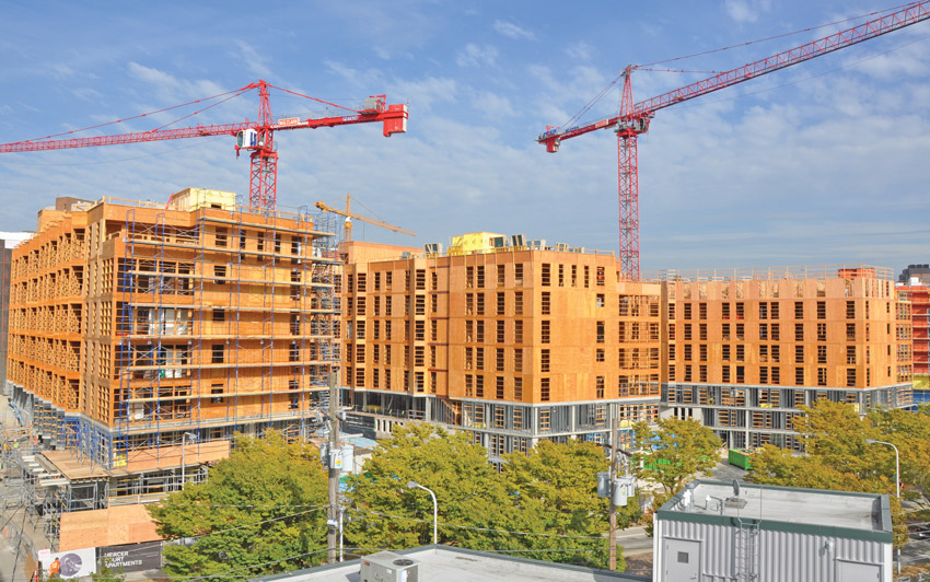
The benefits of choosing wood in commercial and nonresidential projects are many. Both light frame and mass timber structural systems offer flexibility in design options. They also are economical and relatively easy to construct, providing ease of use on the job site. Yet one important benefit that should not be overlooked is the thermal performance that wood can provide. Thermal performance contributes to a range of important goals for most projects, including energy efficiency, comfort, durability, code compliance, structural integrity, and sustainable outcomes. Designing with wood not only meets performance requirements for commercial and nonresidential buildings—it can also exceed goals.
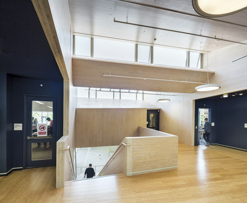
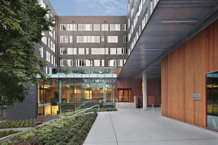
Photo: David Sundberg + Gray Organschi Architecture
Common Ground High School
Designing with wood offers architects the flexibility to design projects with increased insulation. From a thermal perspective, wood-frame building enclosures are inherently more efficient than steel-frame, concrete, or masonry construction.1 This advantage stems from the insulating qualities of the structural elements of wood, including studs, columns, beams, and floors, but also the fact that wood stud walls are easy to insulate. Wood has the bonus benefit of allowing less thermal bridging, as the relative R-value of wood is higher than steel and masonry.2
The Natural Thermal Properties of Wood
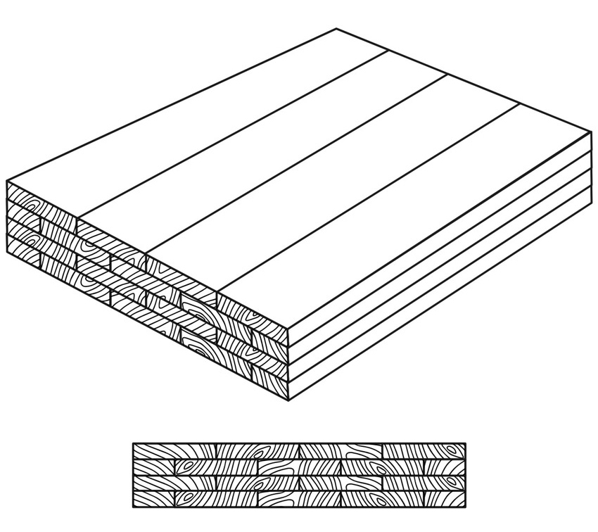
Wood naturally provides insulation benefits due to its inherent structure. Air pockets within timber’s cellular structure create a barrier to heat and cold, similar to air pockets found in most types of insulation. The air pockets reduce the thermal conductivity of wood, slowing heat transfer and helping to reduce thermal bridging. Thermal conductivity, or the ease with which heat energy flows through the material, declines as the density of the wood decreases.3 This means that modern softwoods have a thermal performance edge over traditional hardwoods.
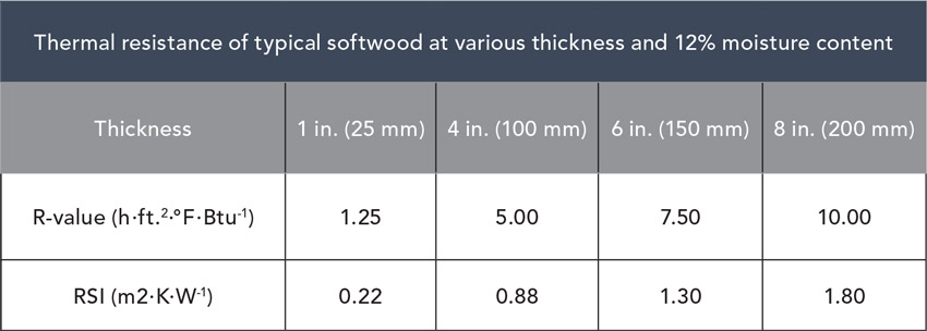
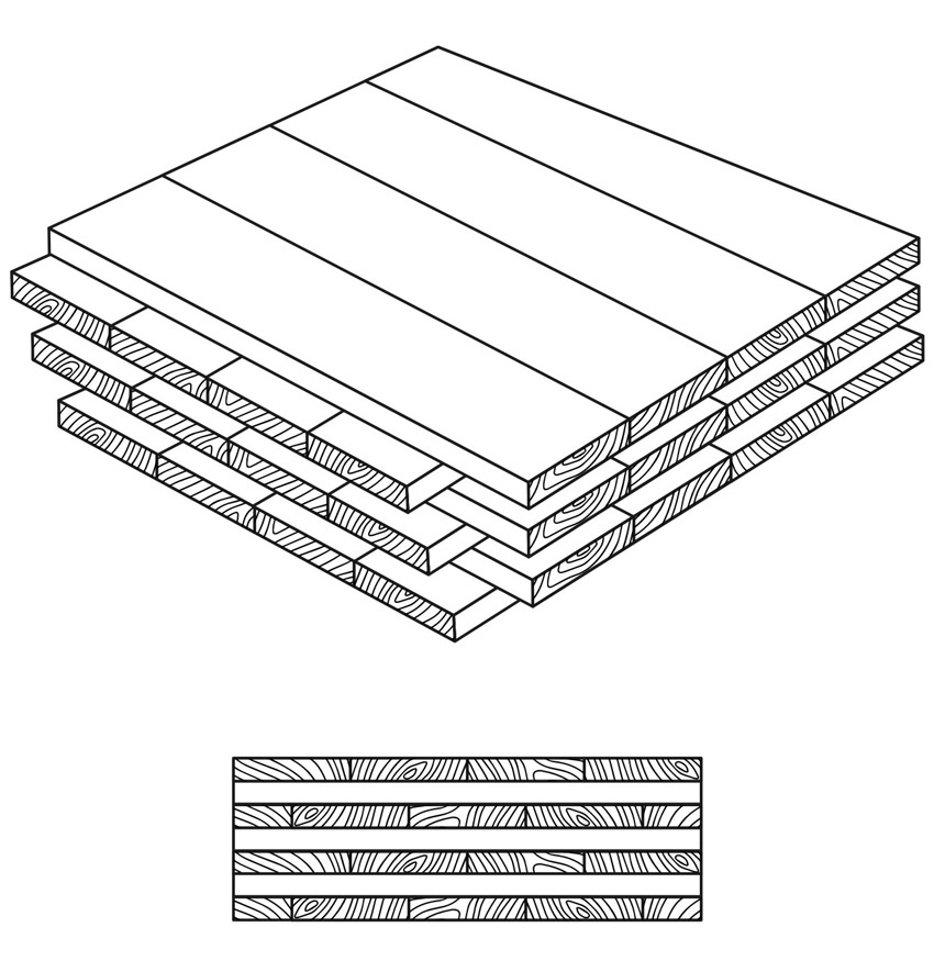
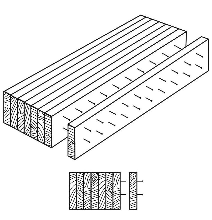
Source: CLT Handbook, U.S. Edition, Chapter 10
The thermal resistance of typical softwood varies depending on thickness and moisture content.
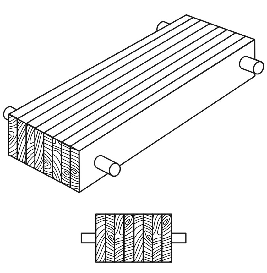
As an organic material, other aspects of wood can alter thermal performance. Grain direction can significantly impact thermal conductivity. For example, thermal conductivity of pine in the direction of the grain is 0.22 W/moC (which is equivalent to degrees Celsius/W) and perpendicular to the grain 0.14 W/moC.4 This is important to know, as dimensional lumber in studs will have less thermal conductivity through the wall and greater heat transfer between the floor and ceiling.
Moisture also plays a part in wood’s thermal performance. Increasing moisture in wood increases thermal conductivity, so kiln-dried wood or fully aged and dried wood will allow less heat transfer than “green” or wetted wood. Keeping wood at the optimum moisture level is important to ensure performance goals are met and maintained over time.
When compared to steel or masonry, wood has a higher thermal resistivity, which improves energy-efficiency performance, especially when used in wall assemblies. Wood studs have nearly four times the thermal resistance of steel studs or masonry blocks. A nominal 2-by-4 stud has an R-value of 4.38, whereas a 3½-inch cold-rolled steel stud has an R-value of 1.34, and an 8-inch nominal concrete masonry unit (CMU) has an R-value of 1.11. The 2018 International Energy Conservation Code (IECC) recognizes this difference and requires continuous insulation on steel and CMU wall assemblies.5
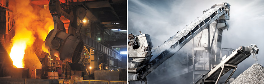
Steel and masonry materials are both energy intensive to produce and do not offer the same inherent thermal properties as wood.
The benefits of choosing wood in commercial and nonresidential projects are many. Both light frame and mass timber structural systems offer flexibility in design options. They also are economical and relatively easy to construct, providing ease of use on the job site. Yet one important benefit that should not be overlooked is the thermal performance that wood can provide. Thermal performance contributes to a range of important goals for most projects, including energy efficiency, comfort, durability, code compliance, structural integrity, and sustainable outcomes. Designing with wood not only meets performance requirements for commercial and nonresidential buildings—it can also exceed goals.
Photo: David Sundberg + Gray Organschi Architecture
Common Ground High School
Designing with wood offers architects the flexibility to design projects with increased insulation. From a thermal perspective, wood-frame building enclosures are inherently more efficient than steel-frame, concrete, or masonry construction.1 This advantage stems from the insulating qualities of the structural elements of wood, including studs, columns, beams, and floors, but also the fact that wood stud walls are easy to insulate. Wood has the bonus benefit of allowing less thermal bridging, as the relative R-value of wood is higher than steel and masonry.2
The Natural Thermal Properties of Wood
Wood naturally provides insulation benefits due to its inherent structure. Air pockets within timber’s cellular structure create a barrier to heat and cold, similar to air pockets found in most types of insulation. The air pockets reduce the thermal conductivity of wood, slowing heat transfer and helping to reduce thermal bridging. Thermal conductivity, or the ease with which heat energy flows through the material, declines as the density of the wood decreases.3 This means that modern softwoods have a thermal performance edge over traditional hardwoods.
Source: CLT Handbook, U.S. Edition, Chapter 10
The thermal resistance of typical softwood varies depending on thickness and moisture content.
As an organic material, other aspects of wood can alter thermal performance. Grain direction can significantly impact thermal conductivity. For example, thermal conductivity of pine in the direction of the grain is 0.22 W/moC (which is equivalent to degrees Celsius/W) and perpendicular to the grain 0.14 W/moC.4 This is important to know, as dimensional lumber in studs will have less thermal conductivity through the wall and greater heat transfer between the floor and ceiling.
Moisture also plays a part in wood’s thermal performance. Increasing moisture in wood increases thermal conductivity, so kiln-dried wood or fully aged and dried wood will allow less heat transfer than “green” or wetted wood. Keeping wood at the optimum moisture level is important to ensure performance goals are met and maintained over time.
When compared to steel or masonry, wood has a higher thermal resistivity, which improves energy-efficiency performance, especially when used in wall assemblies. Wood studs have nearly four times the thermal resistance of steel studs or masonry blocks. A nominal 2-by-4 stud has an R-value of 4.38, whereas a 3½-inch cold-rolled steel stud has an R-value of 1.34, and an 8-inch nominal concrete masonry unit (CMU) has an R-value of 1.11. The 2018 International Energy Conservation Code (IECC) recognizes this difference and requires continuous insulation on steel and CMU wall assemblies.5
Steel and masonry materials are both energy intensive to produce and do not offer the same inherent thermal properties as wood.
Thermal Values and Code Considerations
While wood-frame buildings have a history of cost effectively achieving energy-efficiency objectives, energy codes and standards maintain the minimum thermal requirements for building enclosure assemblies. The IECC sets minimum energy-efficiency provisions for both residential and commercial buildings and offers two methods for showing compliance: the prescriptive path and the performance path. The most recent IECC requirements are from 2018; however, for commercial wood-framed walls, there have been no changes or updates since the 2015 edition, so the previous standards still apply.
The prescriptive path of the code sets specific minimum performance levels for each of the components of the building envelope. The design of the building is parsed out into each component of the envelope, including wall insulation, window U-factor, air infiltration, and solar heat gain coefficient (SHGC). Under the prescriptive path, each component must meet or exceed specific performance requirements, without the ability to tradeoff between components. Although the prescriptive path can be more rigid to follow, this option is very straightforward and can be easier to meet. The prescriptive path can be considered the R-value path in which each material (component) must meet a specific numerical requirement for resisting thermal or heat transfer. Note that a higher R-value is better when considering the reduction of heat transfer.
The performance path can be thought of as a U-factor guide that allows for tradeoffs between components, as energy calculations are used to determine if the tradeoffs result in performance that is equivalent to the prescriptive requirements. The U-factor is the reciprocal of the R-value and indicates the rate of thermal transfer. The lower the U-factor, the lower the transmission rate and the better the thermal performance or efficiency. While the performance path offers more flexibility, it requires a closer look at each specific building envelope component and how they perform together to ensure ultimate compliance. At times, use of the prescriptive path is required if, for instance, a commercial building design exceeds 40 percent window to wall area.
A third path for compliance is to follow the American Society of Heating, Refrigerating, and Air-Conditioning Engineers (ASHRAE) 90.1 path. This standard was developed jointly by the American National Standards Institute (ANSI), ASHRAE, and Illuminating Engineering Society of North America (IESNA) and provides the minimum requirements for energy-efficient design of most buildings, except low-rise residential buildings. It offers, in detail, the minimum energy requirements for design and construction of new buildings and their systems, new portions of buildings and their systems, and new systems and equipment in existing buildings, as well as criteria for determining compliance with these requirements. The most recent update to ASHRAE 90.1 is the 2016 edition that requires building envelope verification in support of reduced air infiltration.
Because of the flexibility that wood provides during the design stage, it is an ideal material to comply with the prescriptive, performance, or ASHRAE 90.1 requirements.
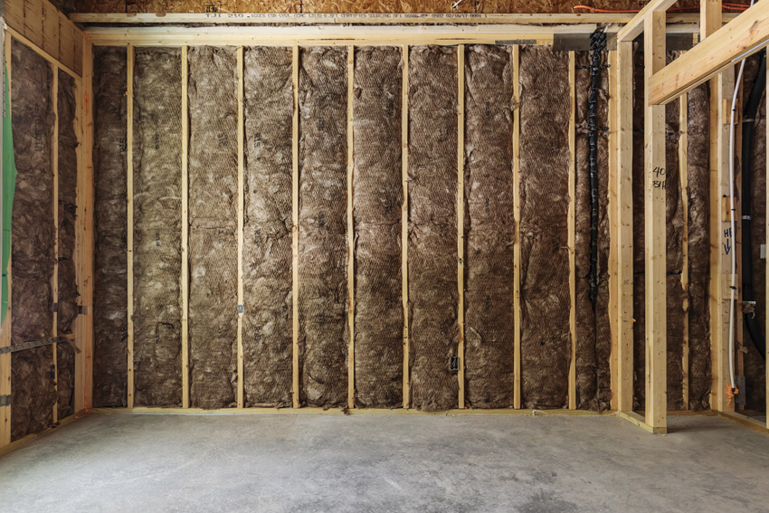
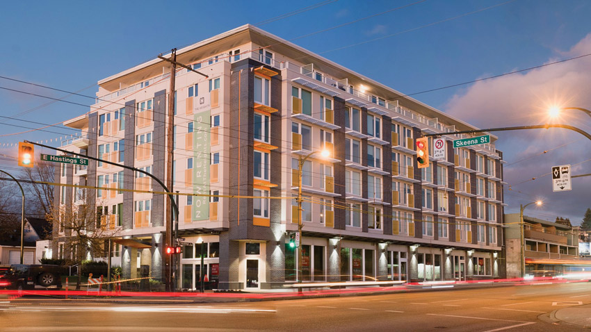
Photo courtesy of Think Wood
Insulation strategies vary, but wood framing allows for options that can improve the overall thermal performance of the building.
Continuous Insulation
One of the key means for achieving energy efficiency in building enclosures is to ensure greater thermal insulation levels throughout the building envelope. Greater insulation combined with a complete moisture- and vapor-barrier strategy can be code compliant and provide exceptional thermal performance, comfort, and durability for the building.
Wood-frame walls are unique in that they are the only component where a choice can be made between two insulation requirements based on the level of continuous insulation desired. Continuous insulation, also known as ci, is defined by ASHRAE 90.1 as insulation that is continuous across all structural members without thermal bridges other than fasteners and service openings. It is installed on the interior, exterior, or is integral to any opaque surface of the building envelope. The purpose is to minimize condensing surfaces in walls and provide an insulation layer in which little to no thermal bridging occurs. In practical terms, continuous insulation is comprised of rigid boards placed end to end, often installed over an entire wall to provide a contiguous layer of insulating material. Following are, however, other options:
Interior Insulated
Insulating layer is located on the interior side of the water-resistive barrier. For walls, this typically means the insulation is located within the stud space. For roofs, the interior insulation may be located above the sheathing but under the roof membrane or, alternatively, below the sheathing within the roof framing. Both are considered interior insulated.
Exterior Insulated
Insulating layer is located on the exterior of the water-resistive barrier—i.e., the likely wet zone. For walls, this means the insulation is located within the drained cavity space, while for roofs this means the insulation is located above the membrane (i.e., an inverted roof or protected membrane assembly). For mass timber systems (e.g., cross-laminated timber walls), this is the preferred insulation strategy to protect the wood from moisture accumulation. Exterior insulation materials must be resistant to the effects of moisture.
Split Insulated
More than one insulating layer is provided, typically with one layer provided to the interior and one layer to the exterior of the water-resistive barrier.
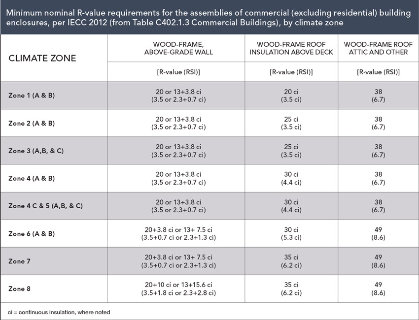
Minimum R-value requirements for above-grade wood-frame building enclosure assemblies in the 2018 IECC are provided for “commercial” buildings (including most multiunit residential buildings) in IECC Table C402.1.3 (see right). They are broken down by climate zone, as defined in the U.S. Department of Energy’s climate zone map.
Under the prescriptive path of the 2018 IECC, walls, floors, and roofs have specific insulation requirements based on framing type and climate zone. For example, above-grade metal-framed walls in climates zones 3 and 4 (except Marine) are required to have R-13 cavity insulation and R-7.5 continuous insulation applied to one face of the wall. The wood-framed walls at the same location are required to have R-13 cavity insulation and R-3.8 continuous insulation or have R-20 cavity insulation with no additional continuous insulation requirements. The option to forego continuous insulation requirements on wood-framed walls with R-20 cavity insulation acknowledges that metal studs have a significantly higher thermal conductance than wood studs. The R-20 cavity insulation option allows wood wall frames with 6-inch-deep studs to meet the prescriptive wall requirements with no continuous insulation in climate zone 4. The R-20 wood-framed wall is the only option available in the IECC prescriptive wall path using prescribed R-values that does not require continuous insulation for above-grade walls.
Unlike the IECC, the prescriptive path of ASHRAE 90.1 does not contain the option to reduce or forego continuous insulation in wood-framed walls with the use of R-20 cavity insulation.
Strategies for Improved Performance with Wood
The natural properties of wood make it a great insulator. When used in conjunction with aggressive insulation strategies, wood can enable an architect to design a building with exceptional thermal performance. To maximize building performance with wood, we will take a look at three aspects of improving a building’s thermal performance: identifying the paths of heat transfer, creating more space for insulation, and creating an aggressive air and moisture barrier.
Limiting Heat Transfer Through Walls
While most heat loss occurs around windows and penetrations in the building envelope, when designing with wood, it is important to look at all aspects of the design to ensure a complete building enclosure strategy. For instance, wall design offers many opportunities to improve the thermal performance of the building, but first you must identify where heat transfer is most likely.
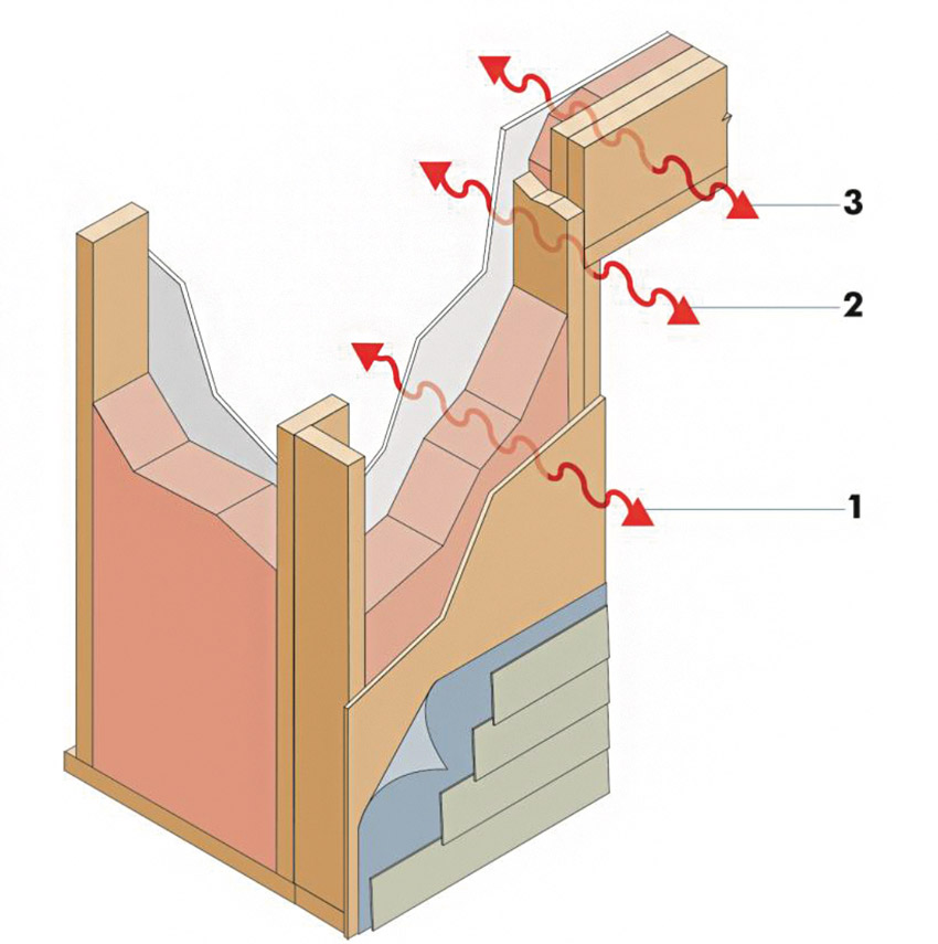
Source: The Role of the Structural Engineer in Net-Zero-Energy Construction
Heat transfer occurs through the cavity insulation, framing members, and headers.6 The three locations offer parallel paths for heat transfer.
Heat transfer occurs through the cavity insulation, framing members, and headers. The three locations offer parallel paths for heat transfer.6
Transfer through the cavity insulation has the most heat resistance due to the absence of framing. With wood included in the design process, this area offers an opportunity to increase overall R-values. Increasing cavity gap by using 2-by-6 studs, employing advanced framing strategies, and staggering stud design are all successful ways to reduce heat transfer through the insulation cavity.
Framing members include studs, top and bottom wall plates, and full-cavity width blocking. Strategies to reduce heat transfer through framing members include incorporating intersecting wall techniques and energy-efficient corners, such as three-stud corners and ladder junctions, that allow for greater insulation volume. Energy-efficient headers and limited framing around openings as well as eliminating double top plates are also effective strategies. Note that eliminating double top plates has its challenges. This step requires vertical framing alignment, including 24-inch-on-center floor and roof framing as well as non-industry standard stud lengths that may be difficult to source. In addition, the use of a single top plate requires metal straps for tension splices, which can contribute to significant thermal bridging.
The third area of heat transfer in walls is through the framing headers that carry structural loads above window and door openings. To improve the thermal performance of headers, more insulation is usually used. Reducing the amount of framing material in headers can be done through use of engineered lumber or single-ply sawn lumber, but care must be taken to ensure the integrity of the load path.
Creating Effective Air Barriers
The control of air leakage is important to conserve space heat and reduce air-conditioning loads. In multistory buildings, air leakage may account for up to half of the space heat loss, depending on the air-leakage rate, building height and wind exposure, occupant behavior, mechanical penetrations, and several other factors, including the enclosure thermal performance.
Air leakage in multistory buildings is typically higher than in smaller, single-family dwellings due to increased wind exposure, the stack effect, and mechanical systems, all of which contribute to higher and more sustained differential pressures across the building enclosure.
Controlling air flow through the use of air-barrier systems is important to minimize the loss of conditioned air through the building enclosures, along with other factors. Air-barrier systems are required for all multiunit residential buildings in all climate zones.
The air barrier is the means of preventing air leakage through the building envelope. A building’s air barrier should be continuous, integrating all the exterior envelope systems—the wall air barrier with the roof air barrier, and so on. The air barrier can be installed on the interior or exterior of the building envelope. An efficient and cost-effective way to achieve an effective air barrier on walls is to incorporate a continuous, solid layer on the exterior of a building. The continuous solid material should be stiff enough to minimize the amount of deflection when pressure is applied to tape or sealants in order to create an effective seal on panel joints and around wall penetrations. Panel joints need to be properly sealed to complete an air-barrier assembly.
Continuous wood structural panel sheathing is commonly used as part of an air-barrier system for exterior walls. The architect typically details how panel joints and openings are to be sealed—usually with tape or sealant specifically recommended for use on plywood or oriented strand board (OSB). Using continuous structural sheathing as part of the air-barrier system also provides a solid support base for exterior cladding systems while increasing the structure’s earthquake and wind resistance.
When using continuous wood structural panels as the air barrier, panels should not be glued directly to framing. This approach is restricted in high Seismic Design Categories per the American Wood Council’s Special Design Provisions for Wind and Seismic (SDPWS) Section 4.3.6.1. Gluing wall sheathing to framing also restricts wood panels from expanding as moisture is absorbed, which can contribute to out-of-plane buckling.
Make sure that any sealant or tape used to complete the air barrier does not impede the ability of the panels to expand when exposed to increased humidity in the wall cavity or wetting due to construction delays. Anything that prevents panel expansion into the recommended ⅛-inch spacing between panels could result in buckling of the wall sheathing. Also, make sure the tape is rated for use as part of an air barrier system.7
A water-resistive barrier, such as housewrap, should always be installed over wood structural panel wall sheathing in order to direct any moisture that penetrates the cladding away from the sheathing and wall cavity.
Unlike vapor barriers, there is little to no downside of redundancy in the air barrier provided the materials used do not negatively impact vapor flow. In fact, some designers incorporate more than one continuous air barrier—one on the building interior and one on the exterior.
Managing Water in the Building Envelope
Similar to controlling air movement, the flow of water in wood-framed buildings must be controlledin the building envelope. Water can ruin insulation, create rot and structural issues, and is the key ingredient contributing to mold growth and associated indoor air quality issues. Water vapor condensation is a major threat to the structure of a house no matter the climate or framing material. In cold climates, pressure differences can drive warm, moist indoor air into exterior walls and attics. The air condenses as it cools. The same can be said for southern climates, just in reverse. As the humid outdoor air enters the walls and encounters cooler wall cavities, it condenses into liquid water.
In most U.S. climates, vapor barriers, or—more accurately—vapor diffusion retarders, should be part of a moisture-control strategy for a home. A vapor barrier or vapor diffusion retarder is a material that reduces the rate at which water vapor can move through a material. The older term “vapor barrier” is still used even though “vapor diffusion retarder” is more accurate. How to design and install vapor retarders depends a great deal on the climate and the chosen construction method. However, a universal truth of building envelope design is that any water vapor that does manage to get into the walls or attics must be allowed to escape.
In mild climates, materials such as painted gypsum wallboard and plaster wall coatings may be enough to impede moisture diffusion. In more extreme climates, higher-perm vapor diffusion retarders are advisable for new construction. They perform best when installed closest to the warm side of a structural assembly—toward the interior of the building in cold climates and toward the exterior in hot/wet climates.
A vapor diffusion retarder installation should be continuous and as close to perfect as possible. This is especially important in very cold climates and in hot and humid climates. Be sure to completely seal any tears, openings, or punctures that may occur during construction. Cover all appropriate surfaces or you risk moist air condensing within the cavity, which could lead to dampened insulation. The thermal resistance of wet insulation is dramatically decreased, and prolonged wet conditions will encourage mold and wood rot.
Combining air barriers and vapor diffusion retarders is becoming more popular, especially in warmer humid climates. An air barrier/vapor diffusion retarder system attempts to accomplish water vapor diffusion and air movement control with one material. This type of material is most appropriate for southern climates where keeping humid outdoor air from entering the building cavities is critical during the cooling season.
In most cases, air barriers/vapor diffusion retarders consist of one or more of the following—polyethylene plastic sheets, foil, foam board insulation as part of a continuous insulation design, and exterior sheathings. Air barriers/vapor diffusion retarders typically are placed around the perimeter of the building just under the exterior finish, or they may actually be the exterior finish. The key to making them work effectively is to permanently and carefully seal all of the seams and penetrations, including around windows, doors, electrical outlets, plumbing stacks, and vent fans.
Conclusion
The inherent properties of wood include strength, durability, sustainability, and flexible design options, which allow architects to design commercial and nonresidential buildings to a higher level of thermal performance. Compared to other building materials, choosing wood framing, both light frame and mass timber, leverages the natural attributes of wood and provides for accessible code compliance and energy savings. Whether choosing light frame design or leveraging the advantages of mass timber products, wood continues to provide economic, structural, and environmentally efficient benefits to designer, builders, and occupants.
End Notes
1Graham, Finch et al. Guide for Designing Energy-Efficient Building Enclosures for Wood-Frame Multi-Unit Residential Buildings in Marine to Cold Climates in North America. FPInnovations and RDH Building Engineering Ltd. 2013. Web. 19 April 2018.
2Upton, Brad et. al. “The Greenhouse gas and energy impacts of using wood instead of alternatives in residential construction in the United States.” Biomass & Bioenergy. Elsevier. 2008. Web. 19 April 2018.
3Wood and Water
4Thermal Properties of Wood
5Code (2018 IECC), Chapter 4 Commercial Energy Efficiency, Section C401. General, Section C402 Building Envelope Requirements
6The Role of the Structural Engineer in Net-Zero-Energy Construction
7Vapor Barriers or Vapor Diffusion Retarders
Resources
CLT Handbook Chapter 10
WoodWorks: Energy Efficiency
American Wood Council
Meeting and Exceeding Energy Objectives in Wood Buildings
Andrew A. Hunt is vice president of Confluence Communications and has been a writer and consultant in the green building and building science industry for over a decade. He has authored more than 100 continuing education and technical publications as part of a nationwide practice. confluencec.com

|
Think Wood is a leading education provider on the advantages of using softwood lumber in commercial, community, and multifamily building applications. We introduce innovators in the field to our community of architects, engineers, designers, and developers. For support or resources, contact us at info@thinkwood.com.
www.thinkwood.com
|