This CE Center article is no longer eligible for receiving credits.
Impact of 9/11 and Initial Response
During the immediate aftermath of the destruction of the Twin Towers at the WTC, transportation, access, businesses, and operations at the World Financial Center were shut down. Other surrounding WTC buildings were damaged and some needed intensive repair and restoration. Others were partially demolished and rebuilt due to structural damage. Across the street, the World Financial Center was mostly intact, but some of the key elements of connectivity with the surrounding neighborhood and the region were lost. Not only were the elevated walkways gone, some of the buildings they connected to were either gone or closed. Further, the transportation systems under the World Trade Center were shut down or re-routed. Hence, the building needed a new means of connectivity to the city, the most logical of which was a purely street-level main entry. Therefore, just four months after the September 11 attacks, Pelli Clarke Pelli Architects (PCPA) was called upon by the building owners, Brookfield Office Properties, to create a new entry on the east side of the complex facing West Street. They were the logical choice since the firm still had architects on staff who worked on the original 1980s building complex. The architects in turn invited back the same structural engineering firm, Thornton Tomasetti, to assist.
It became readily apparent that the owners wanted a quick solution and saw an opportunity to provide a psychologically significant milestone—they wanted the new entry and related work completed by the first anniversary of the attacks. In other words, design, construction, approvals, and hand-over in less than nine months. Despite the inherent challenge, the project team agreed to the exceptional timeframe. What followed was an understandably intense period of full collaboration between the architects, engineers, contractors, and the owner.
A new glass façade and canopy design was worked out to establish a new entry to the east of the Winter Garden area of the WFC complex. For continuity, some materials selected to match the existing building could only be fabricated in Europe and elsewhere. In spite of the deadline, those fabricators and installers rose to the occasion. Craig Copeland, the project design team leader for PCPA, recalls, “It was indicative of the project's importance that companies around the country and world dropped what they were doing to focus their attention on meeting the significant deadline.”
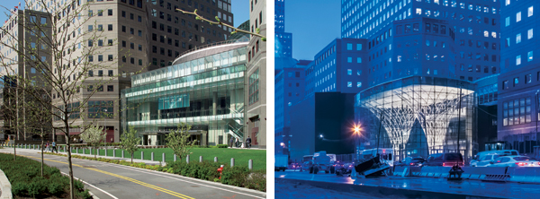
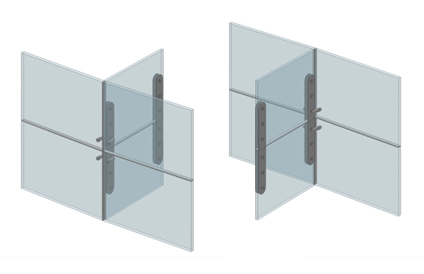
Left photo courtesy of Pelli Clarke Pelli Architects; Right photo © Jeff Goldberg/Esto
The 2002 temporary entry is shown on the left and the new entry pavilion on the right; both came about because of the full collaboration of the design team, contractors, and owner.
The push was on. PCPA set up a field office so designers and contractors could hold daily meetings, sometimes several times a day, around the site to coordinate details, anticipate upcoming work, and keep all things flowing. It wasn't a typical project delivery process, but this wasn't a typical project. Through perseverance and a genuine spirit of cooperation and collaboration, the entire team successfully turned over a completed project on September 10, 2002—a day before the one-year anniversary. The resulting new entry and canopy provided the WFC complex with the needed connectivity to West Street, established a new circulation flow, and helped make the entire complex functional and operational again.
Changing Building Needs
While the WFC was able to act quickly, such was not the case for the rest of the area. The loss of the Twin Towers and the residual impact to the immediate area meant the necessary exodus of numerous businesses from lower Manhattan. Further, plans began almost immediately to redevelop the WTC site—it would eventually include a memorial, a museum, a new underground PATH train station, and new or renovated buildings including the new 1,776-foot-tall One World Trade Center. All of this redevelopment was seen as positive overall, but changed the nature and makeup of the area surrounding the World Financial Center complex. Further, the directly adjacent Battery Park City was expanding in its redevelopment to include mixed-use residential, retail, outdoor space, and neighborhood amenities. It soon became apparent to Brookfield Office Properties that the demographics around their buildings were shifting from a predominantly financial office environment to a much more diverse working and living population.
The owners began to assess how best to respond to these changes. They first initiated some building renovations: Lower-level office areas were changed over to retail and mixed uses including restaurants, shopping, and other amenities. The Winter Garden played prominently in that change, serving as a focal point for some of this transformed activity and as an internal connection point to access many of them. Office spaces remained on the upper floors with an updated mix of tenants and businesses. Then, as both a symbolic and practical action, the owners decided to change the property's name from the World Financial Center to Brookfield Place. More than just a name change, their intent was to reframe the identity of the complex to reflect its increasingly diverse use and population.
Concurrent with all of this activity, a proposal emerged for the Port Authority to provide a set of escalators from the space east of the Winter Garden to a PATH station being designed by Santiago Calatrava at the WTC site. Along with the new escalators, and a fresh building identity, Brookfield wanted to restore the complex's ability to connect directly with its surroundings, namely the PATH and WTC. Hence, a single, multipurpose main entry in front of the Winter Garden that connected to the street, the escalators to the trains, and to the Brookfield Place complex seemed to suit the situation best.
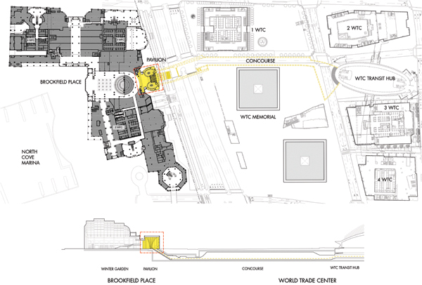
Image courtesy of Pelli Clarke Pelli Architects
Plan of the PATH train that passes under Brookfield Place on the left with new escalators that connect to the trains and the new station on the fight
Collaborating to Fulfill the Change
Having experienced such a successful collaboration with the 2002 entrance and canopy projects, the owners once again called upon the architectural and engineering team of Pelli Clarke Pelli Architects, Flack + Kurtz (now WSP), and Thornton Tomasetti to devise a solution to reconnect with the WTC. Following an open bid process, Brookfield Properties selected Plaza Construction to provide overall construction management.
Site Conditions Influencing Design
The design team began assembling more detailed site information related to the entry area. The canopy was lightweight, affected only areas at or near grade, and was fairly easy to accommodate. But what was needed was a fully enclosed building with access to below-grade areas that would make more demands on the site, which already had many existing below-grade structures, utilities, and other items to consider.
Foremost of these existing items, the highly publicized “bathtub” foundation that surrounded the World Trade Center site below grade to hold back groundwater pressure, ran almost directly under the entry location. Obviously this important structure could not be breached or used to exert new structural loads. The nearby underground transportation provided part of the reason for a new enclosure, but also meant that the enclosure could not interfere or interrupt any of the tracks, tunnels, or related structures associated with it. The Port Authority had jurisdiction over these areas and needed to be consulted in order to understand and assess specific restrictions and opportunities for connection. Further, since these transportation systems were approximately 50 feet below street level, long escalators would be required to access them. That meant they would likely extend out under the street and would need to avoid any existing utilities and other infrastructure located there.
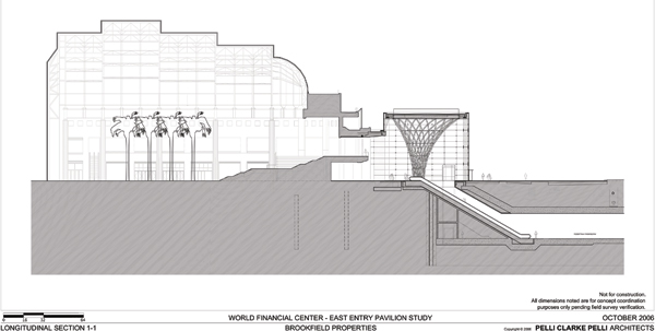
Image courtesy of Pelli Clarke Pelli Architects
Architectural section showing the new entry pavilion that connects the Winter Garden on the left to the escalators and below ground PATH station on the right
After collecting all of the needed and relevant information about the existing site conditions, it became apparent that there were only two spots where any significant structural loads could be located. These points were on the left and right of the entry area but restricted as to their location between the street and the Winter Garden—meaning that they were in the center of the space, not the perimeter. While the assumption was always that the entry pavilion would be appropriately separated or isolated structurally from the Winter Garden, the extent of the site limitations was well beyond common or anticipated. Moving to a different location was not an option since the Winter Garden connection remained critical to the new complex's function. Further, it provided the most visible option for such an entry pavilion with the opportunity to make the best design impact. While structurally limited, it would need to create an appropriate visual statement that indeed looked properly connected to the newly named Brookfield Place, the street, and the transportation systems below.
Around the country, architects are perfecting the art of effective collaboration to produce highly successful projects. Building design and construction are influenced by increasingly complex demands and user requirements, particularly in dense, urban settings. One such example is a highly visible and significant project in the area around the site of New York City's former Twin Towers at the World Trade Center in Lower Manhattan.
The project involved design and construction of an entry pavilion to the Winter Garden and World Financial Center, located across the street from the World Trade Center, which was heavily impacted by the attacks of 9/11. Perhaps no other project in the country illustrates more clearly the challenges and benefits of an architect-led, collaborative, project-delivery process, or integrated project delivery (IPD).
Collaboration Through Integrated Project Delivery
The increasingly intricate and complex forces at work during a building's design and construction can be seen as an evolution. The use of advanced computing capabilities such as computer-aided design and documentation (CADD) or three-dimensional building information modeling (BIM)—used not just by designers but by constructors and fabricators as well—have greatly affected the field of construction. Some evolution has also occurred due to fluctuating economic conditions, which in turn have led owners to require greater efficiency, communication, and overall coordination across project teams. These elements have led everyone in the building industry to question traditional approaches to the processes used to create projects.

Photo © Jeff Goldberg/Esto
The new entry pavilion of Brookfield Place in New York City is an excellent example of structural innovation and professional collaboration to create a successful project responding to changing needs.
Recognizing these changes, the American Institute of Architects (AIA) has developed a member-approved position statement on project delivery, which is simply defined as the process that a project follows from inception to completion. The concept of integrated project delivery has been articulated under the leadership of AIA National and AIA California Council. In many locations, the thinking surrounding IPD has gained ground and is becoming more commonplace—there are even formal AIA Contract templates built around collaborative multi-party agreements. In some locations, IPD still remains an ideal to strive for. We will focus here on the Brookfield Place project as a case study for the ways that unique project requirements and complex, sometimes competing demands can bring about greater collaboration among all involved to achieve very successful results.
Case Study Context: The World Financial Center in New York City Prior to 9/11
Most people remember the terrorist attacks of September 11, 2001, as the destruction of the Twin Towers at the World Trade Center in New York City. The reality is that a large section of lower Manhattan was impacted on this day. Prior to 9/11, the Twin Towers were certainly the most visible on this part of the city's skyline, but they also existed as an integral part of a complex of other related buildings, transportation systems, and public spaces collectively referred to as the World Trade Center (WTC). Geographically, the towers and the WTC bordered the redeveloped and desirable Battery Park City neighborhood. Functionally, they were seen as part of the nearby financial district that includes Wall Street and the New York Stock Exchange.
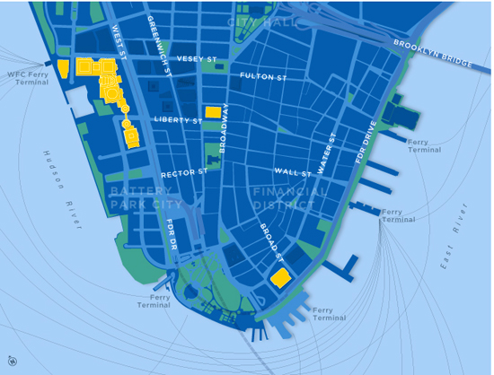
Map courtesy of Brookfield Office Properties
Site plan showing the location of World Financial Center, now Brookfield Place (shown in yellow on the left), across the street from the World Trade Center site and the former Twin Towers
Just to the west of the WTC, the World Financial Center (WFC) fills most of the land between West Street (a.k.a. the West Side Highway) and the Hudson River. This complex of award-winning buildings was designed by Cesar Pelli & Associates (now Pelli Clarke Pelli Architects) in 1988. The complex includes four mid-rise towers with distinctive geometric roofs and solid façades punched with iconic square window openings. The buildings are certainly lower than the Twin Towers, which were once tallest in the world, but with heights between 34 and 52 floors, they are easily seen along the Hudson River and from across the street at the World Trade Center site.

Photo © Jeff Goldberg/Esto
A view of Brookfield Place looking across the WTC site. The curving glass enclosure of the Winter Garden sits behind the new entry pavilion but in front of the Hudson River and is flanked by two of the towers of the complex.
Equally visible and significant to the WFC complex is the inclusion of a large, glass-enclosed Winter Garden that serves as a combination public space and circulation area. In its public-use mode, the Winter Garden is a setting for special events, and, with its prominent palm trees and abundant daylight, is an everyday respite from the surrounding urban environment. As a circulation area, it serves as part of a series of pedestrian walkways between the different WFC towers as well as a connection to the Hudson River where a ferry dock and marina are located. Since the Winter Garden creates a visual break between the adjacent taller buildings and has an eastern façade facing West Street, it has become the de facto “front door” of the entire WFC complex.
Before 9/11, the appeal for tenants and employees in the World Financial Center was not only its location and proximity to other financial and business-focused buildings, but also its connectivity to them and other parts of the surrounding area. Public access routes connected the different portions of the World Financial Center to each other, to the World Trade Center across the street, and other nearby buildings. However they also connected to needed public transportation systems such as the New York City subway, the New Jersey PATH train, city buses and ferries. These transportation systems were all valued and relied upon daily by commuters or visitors. This connectivity was equally valued by the owners of the buildings, Brookfield Office Properties. Just as important, they valued fully enclosed connectivity to avoid inhospitable weather for this primarily pedestrian population. This was realized through the use of elevated, fully enclosed walkways that spanned above West Street to connect the WFC with other buildings and transportation systems. Of course, this meant that those connection points needed to be coordinated with the owners and operators of other buildings and transportation systems, the most prominent of which was the Port Authority of New York and New Jersey. Through this combination of spaces, connectivity, and cooperation, this area functioned quite well for a dense urban location with tens of thousands of people accessing it daily while still offering many desirable amenities.
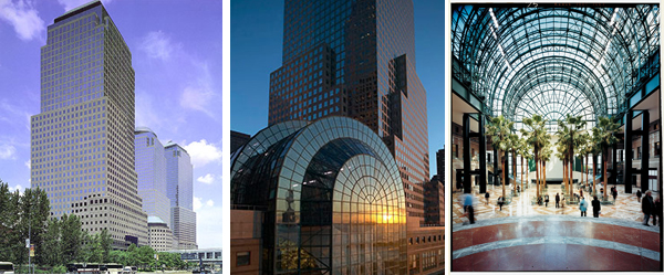
Photos courtesy of Brookfield Properties
The towers of the World Financial Center/Brookfield Place and the centrally located Winter Garden with the interior daylit space planted with palm trees
Impact of 9/11 and Initial Response
During the immediate aftermath of the destruction of the Twin Towers at the WTC, transportation, access, businesses, and operations at the World Financial Center were shut down. Other surrounding WTC buildings were damaged and some needed intensive repair and restoration. Others were partially demolished and rebuilt due to structural damage. Across the street, the World Financial Center was mostly intact, but some of the key elements of connectivity with the surrounding neighborhood and the region were lost. Not only were the elevated walkways gone, some of the buildings they connected to were either gone or closed. Further, the transportation systems under the World Trade Center were shut down or re-routed. Hence, the building needed a new means of connectivity to the city, the most logical of which was a purely street-level main entry. Therefore, just four months after the September 11 attacks, Pelli Clarke Pelli Architects (PCPA) was called upon by the building owners, Brookfield Office Properties, to create a new entry on the east side of the complex facing West Street. They were the logical choice since the firm still had architects on staff who worked on the original 1980s building complex. The architects in turn invited back the same structural engineering firm, Thornton Tomasetti, to assist.
It became readily apparent that the owners wanted a quick solution and saw an opportunity to provide a psychologically significant milestone—they wanted the new entry and related work completed by the first anniversary of the attacks. In other words, design, construction, approvals, and hand-over in less than nine months. Despite the inherent challenge, the project team agreed to the exceptional timeframe. What followed was an understandably intense period of full collaboration between the architects, engineers, contractors, and the owner.
A new glass façade and canopy design was worked out to establish a new entry to the east of the Winter Garden area of the WFC complex. For continuity, some materials selected to match the existing building could only be fabricated in Europe and elsewhere. In spite of the deadline, those fabricators and installers rose to the occasion. Craig Copeland, the project design team leader for PCPA, recalls, “It was indicative of the project's importance that companies around the country and world dropped what they were doing to focus their attention on meeting the significant deadline.”
Left photo courtesy of Pelli Clarke Pelli Architects; Right photo © Jeff Goldberg/Esto
The 2002 temporary entry is shown on the left and the new entry pavilion on the right; both came about because of the full collaboration of the design team, contractors, and owner.
The push was on. PCPA set up a field office so designers and contractors could hold daily meetings, sometimes several times a day, around the site to coordinate details, anticipate upcoming work, and keep all things flowing. It wasn't a typical project delivery process, but this wasn't a typical project. Through perseverance and a genuine spirit of cooperation and collaboration, the entire team successfully turned over a completed project on September 10, 2002—a day before the one-year anniversary. The resulting new entry and canopy provided the WFC complex with the needed connectivity to West Street, established a new circulation flow, and helped make the entire complex functional and operational again.
Changing Building Needs
While the WFC was able to act quickly, such was not the case for the rest of the area. The loss of the Twin Towers and the residual impact to the immediate area meant the necessary exodus of numerous businesses from lower Manhattan. Further, plans began almost immediately to redevelop the WTC site—it would eventually include a memorial, a museum, a new underground PATH train station, and new or renovated buildings including the new 1,776-foot-tall One World Trade Center. All of this redevelopment was seen as positive overall, but changed the nature and makeup of the area surrounding the World Financial Center complex. Further, the directly adjacent Battery Park City was expanding in its redevelopment to include mixed-use residential, retail, outdoor space, and neighborhood amenities. It soon became apparent to Brookfield Office Properties that the demographics around their buildings were shifting from a predominantly financial office environment to a much more diverse working and living population.
The owners began to assess how best to respond to these changes. They first initiated some building renovations: Lower-level office areas were changed over to retail and mixed uses including restaurants, shopping, and other amenities. The Winter Garden played prominently in that change, serving as a focal point for some of this transformed activity and as an internal connection point to access many of them. Office spaces remained on the upper floors with an updated mix of tenants and businesses. Then, as both a symbolic and practical action, the owners decided to change the property's name from the World Financial Center to Brookfield Place. More than just a name change, their intent was to reframe the identity of the complex to reflect its increasingly diverse use and population.
Concurrent with all of this activity, a proposal emerged for the Port Authority to provide a set of escalators from the space east of the Winter Garden to a PATH station being designed by Santiago Calatrava at the WTC site. Along with the new escalators, and a fresh building identity, Brookfield wanted to restore the complex's ability to connect directly with its surroundings, namely the PATH and WTC. Hence, a single, multipurpose main entry in front of the Winter Garden that connected to the street, the escalators to the trains, and to the Brookfield Place complex seemed to suit the situation best.
Image courtesy of Pelli Clarke Pelli Architects
Plan of the PATH train that passes under Brookfield Place on the left with new escalators that connect to the trains and the new station on the fight
Collaborating to Fulfill the Change
Having experienced such a successful collaboration with the 2002 entrance and canopy projects, the owners once again called upon the architectural and engineering team of Pelli Clarke Pelli Architects, Flack + Kurtz (now WSP), and Thornton Tomasetti to devise a solution to reconnect with the WTC. Following an open bid process, Brookfield Properties selected Plaza Construction to provide overall construction management.
Site Conditions Influencing Design
The design team began assembling more detailed site information related to the entry area. The canopy was lightweight, affected only areas at or near grade, and was fairly easy to accommodate. But what was needed was a fully enclosed building with access to below-grade areas that would make more demands on the site, which already had many existing below-grade structures, utilities, and other items to consider.
Foremost of these existing items, the highly publicized “bathtub” foundation that surrounded the World Trade Center site below grade to hold back groundwater pressure, ran almost directly under the entry location. Obviously this important structure could not be breached or used to exert new structural loads. The nearby underground transportation provided part of the reason for a new enclosure, but also meant that the enclosure could not interfere or interrupt any of the tracks, tunnels, or related structures associated with it. The Port Authority had jurisdiction over these areas and needed to be consulted in order to understand and assess specific restrictions and opportunities for connection. Further, since these transportation systems were approximately 50 feet below street level, long escalators would be required to access them. That meant they would likely extend out under the street and would need to avoid any existing utilities and other infrastructure located there.
Image courtesy of Pelli Clarke Pelli Architects
Architectural section showing the new entry pavilion that connects the Winter Garden on the left to the escalators and below ground PATH station on the right
After collecting all of the needed and relevant information about the existing site conditions, it became apparent that there were only two spots where any significant structural loads could be located. These points were on the left and right of the entry area but restricted as to their location between the street and the Winter Garden—meaning that they were in the center of the space, not the perimeter. While the assumption was always that the entry pavilion would be appropriately separated or isolated structurally from the Winter Garden, the extent of the site limitations was well beyond common or anticipated. Moving to a different location was not an option since the Winter Garden connection remained critical to the new complex's function. Further, it provided the most visible option for such an entry pavilion with the opportunity to make the best design impact. While structurally limited, it would need to create an appropriate visual statement that indeed looked properly connected to the newly named Brookfield Place, the street, and the transportation systems below.
Design Scheme
Despite the limitations and complexity of what might have been an otherwise straightforward design problem, the architects and engineers dove into it looking for options for innovation. By collaborating together from the very start, they accepted the challenge to create a design that was open, inviting, and fresh with only two points of support. The concept agreed upon early in the design was to extend the glassy, open feeling of the Winter Garden eastward towards West Street and to offset the otherwise massiveness of the buildings. In an era where security consciousness was elevated to new levels, this was a bold and optimistic decision suggesting a sense of overcoming, rather than being dominated by, the attacks.
Further, the team recognized that in the interest of creating a place with proper scale and proportion to be visibly prominent, the pavilion would coincidentally need to be as tall as the train tracks were deep—around 50 feet above street level.

Photo © Jeff Goldberg/Esto
The open, basket-weave columns became the most prominent design feature of the pavilion due to collaboration and cooperation among all.
The structural options for the entry were assessed as much in terms of functionality as overall design impact. If two massive piers were selected to support a roof system, the appearance and the structure would likely be heavier than desired. Perimeter wall supports were not an option since there was no place to locate a proper perimeter foundation for them. Instead, the designers reasoned that an alternative based on the idea of hanging a curtain wall from a roof structure would be needed.

Images courtesy of Pelli Clarke Pelli Architects
Architectural concept drawings and sections showing the new entry using the basket-weave columns to support the structure that connects the Winter Garden to the escalators and PATH station
The floor slab would need to be designed to be structurally and thermally isolated from all of the things around and below it but still provide the needed space, access, and finishes desired.
After much collaboration and deliberation between the designers, owners, and construction team, a final design concept was agreed upon that blended a sound structural approach with an elegant design. The entry pavilion would be a 54-foot-tall, 8,000-square-foot enclosure that, although first conceived as rectilinear, emerged as a gentle, curving, and inviting perimeter shape. The roof would be supported by two similarly curving columns that provided support in a unique manner. Structurally, it was advantageous to flare out the columns at the top to collect the roof loads and narrow them at the base in a tree-like fashion. The final design proposed that these columns not be solid, but rather a type of spiraling, angled, woven basket form. The material would be hollow, round, structural steel tubes that could be placed in a geometrically stable shape. There was certainly precedent in New York for diagrid-type structural systems that use angular bracing to interlock with horizontal or vertical members, such as the Hearst Tower on Eighth Avenue designed by Sir Norman Foster. But this was literally a new twist on an old concept. The idea was that each woven column would have two sets of opposing, angled, spiraled members that would be held in place by a series of horizontal tension/compression rings in addition to their roof and foundation connections.
The roof structure itself was conceived as a diaphragm using deep structural steel beams that cantilevered off of the two columns along both axes. While they would of course be sized to handle the design live and dead loads of the roof, they also had additional engineering considerations. Since the wall enclosure needed to be suspended from the roof, the steel members needed to accommodate the additional dead load of the proposed curtain wall system. And since that curtain wall system could not be used to carry building shear loads, the roof structure needed to pick those up as well. All of the forces from the roof structure, the hanging curtain wall, and imposed live loads from wind or snow would then be transferred to the basket-like columns and ultimately to their foundations. The foundations would need some special attention and detailing since the connection of the multiple steel tubes to the concrete would not be a typical connection.
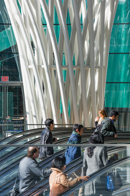
Photo © Jeff Goldberg/Esto
The purpose of the entry pavilion is to move tens of thousands of people a day, a task accomplished in grand style with an open, elegant design.
Of course, the purpose of the entry pavilion was to move people—tens of thousands of people every day. The ultimate layout was very symmetrical with a bank of six escalators located in the center flanked on either side by the two spiraling basket column formations. Elevators were placed toward the street on either side of the escalators and under the overhanging portions of the columns. The perimeter wall included strategically located revolving and swinging doors to access the street on all sides. The connection to the Winter Garden and the rest of Brookfield Place was directly opposite the top of the escalators and fed from the rest of the space. In short, it became a balance of flow, form, and function that linked rather elegantly a set of disparate elements.

Photos courtesy of Pelli Clarke Pelli Architects
The fabrication and installation of the open-weave columns was enhanced and made possible through the successful collaboration of designers, contractor, fabricators, and installers.
Fabrication and Construction Collaboration
With an agreed upon design, the focus shifted to more detailed engagement with those who would be constructing, fabricating, and installing all of the design components to create a unified whole. While simple in concept, the building and its structure were complex in execution. Let's look closer at each of the major components:
• Foundation and concrete floor. Some perimeter foundation was obviously needed, but it was minimally conceived to surround the enclosure, create openings to the escalator area, and contain the floor slab. In reviewing the design of the space with the project's mechanical and electrical engineers, Flack + Kurtz, the question became where to place and run the requisite equipment, ductwork, piping, etc. Rather than expose these components, or add weight to the roof, the engineers suggested containing everything in the floor or just below. A radiant flooring system was undertaken for heating with under-floor ductwork and equipment for cooling. Similarly, a series of electrical lights was incorporated into the floor for general and focused up-lighting within the space. Some additional lights were installed in the ceiling. In the end, a lot of coordination was needed between all parties to locate within a very thin layer the concrete reinforcing, radiant heating, electrical wiring, and openings—all of which needed to weave around doorways and floor openings for ductwork and vertical access.
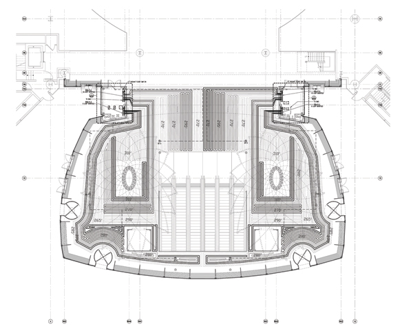
Image courtesy of Pelli Clarke Pelli Architects
The concrete floor slab design required extensive coordination of mechanical and electrical work plus accommodation for all horizontal and vertical access.
• Columns. Due to their innovative nature, the columns obviously took a good bit of collaboration to create successfully. The process began with the architects producing an initial 3D computer model of the basket-weave columns as part of the overall building design. They then shared that model with the structural engineer who imported it into engineering software in order to develop the loading, member sizing, and connection design. This provided an initial feedback loop to the architects to refine the design and allow for the realities of the needed 6-inch interior diameter steel tubes and the compression/tension rings that would be required. Next, the steel fabricator was brought in, and in turn imported the engineer's computer model into their own fabrication program to develop its own production model for review. This provided a final fabrication model that was within an inch of the architect's original 54-foot-tall model and found to be quite acceptable.
The two basket superstructures were developed as spirals where all of the pipes are curving in one direction on the outside and another on the inside—counter-twisting to offset the inherent torque. It was apparent to everyone involved that the columns could be fabricated best under factory conditions where the temperature, weather, and working environment could be controlled. However their sheer size made them too large to be shipped fully assembled to the site. So, the fabricator, engineer, and architect worked together to devise a segmented design. The fabricator, Metropolitan Walters, LLC, was instrumental in devising this scheme to create each column that could be successfully fabricated in discreet sections that could be tested, assembled, shipped, and assembled on site.
The basket columns were conceived of as five vertical tiers separated by compression/tension rings. The architects thought that these rings would be the point of connection between the tiered segments. However, it was the fabricator who pointed out that there would be issues of assembly with that idea—hands and tools would not be able to do the work in the field to make a successful connection. Instead, they pointed out that it would be better to do those connections to the rings in the shop. Hence, they moved the connection points slightly above these compression/tension rings by extending the spiraling hollow tubes past the rings. Then, solid pieces of steel could be inserted into the hollow tubes to align and make the final connections.
Because the limiting factor for a tiered section was the capacity of shipping on a flatbed truck, each column had multiple fabricated sections. The first two tiers were fabricated as one piece in the plant. The third tier required two sections, the fourth required three, and the fifth was fabricated in four sections. The pieces of tiers three through five were assembled onsite by stacking the sections side by side. Since the goal was to avoid any complicated welds at intersection points, they created an x-brace that would be the joint, rather than a straight joint. All of intervention and collaboration with the fabricator was critical to the ultimate reality of determining how to create the finished columns. In the shop, they welded each of the first two tiers together in their entirety for shipping. When they got to the next tiers in sections they set up a system to mechanically fasten and bolt them together to make sure all the pipes aligned. Once they were confirmed in the shop, they removed these temporary bolts and shipped them to the site. In the field, the sections were reassembled and when all was properly in place then the tubes were welded in the field and ground smooth. The final step included painting to give the columns their finished, uniform look.
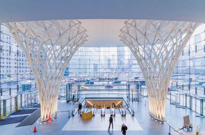
Photo © Jeff Goldberg/Esto
When all was complete, the open, basket-weave columns were well within allowable tolerances and matched the design intent exactly.
Once again, the project design team leader Craig Copeland was impressed at the collaboration used to solve the fabrication and installation issues with the basket-weave columns. “Like any great solution, once the staging strategy was revealed it seemed very simple and obvious but we really struggled as a team to figure that out. The final solution to the sequencing is ultimately to Metropolitan Walter's credit.” When all was complete, the installed columns were well within allowable tolerances and matched the design intent exactly.
• Roof. Acknowledging the multiple functions of the roof structure, the entire team worked together to assure that all demands were appropriately met. The live and dead loading were fairly conventional as was the cross bracing to ascertain rigidity for not only the roof, but the building as it connected to the two basket-weave columns. At the very top of each column a ring plate is used with a more conventional beam diaphragm on top of the ring plates. From there, a series of appropriately sized beams are seated to support the poured-in-place concrete roof deck. All of these components work together to provide the needed lateral stability.
However, hanging the curtain wall raised some concern over deflection from its weight along the perimeter. The engineers and fabricators determined that the best approach would be to pre-tension the roof structure so that when the weight was added around the perimeter, it would draw the structure down to its proper resting level. This was all readily calculable and in the end worked out quite well, thus avoiding undue stress and strain to the roof structure and to the curtain wall system.
• Curtain wall. The fabrication of the curtain wall required intense collaboration as well. All of the weight is supported from above from a series of 4-foot-deep glass fins that hang from a steel connector welded to the roof diaphragm and bolt connected to the fin with a single pin so that it can move. Each fin is held in place laterally by a combination of adjacent panels and a trough at the bottom for lateral stability. There is no gravity load on the ground at all making it a true 54-foot-tall curtain wall. This height required deep, perpendicular glass fins for rigidity and wind resistance to complement the overall design scheme. The architects decided to make them rectilinear. The team also felt that the basket superstructure should be the emphasis, so they did everything possible to make the glass wall clear and open. The fabricated glass panels are 4.5 x 10 feet in size and made with clear, low-iron glass. When a visitor looks at an angle across all of the fins, they can realize that it's glass and perhaps be amazed at how much glass they are looking through. All of these effects only came about because the curtain wall fabricator, Permasteelisa/Gartner, was brought into the collaboration early on, allowing the details of creating a clear system with a minimum of visual disruption to be developed and finalized.
Images courtesy of Pelli Clarke Pelli Architects
The low-iron glass curtain wall was meant to be as transparent as possible using clear glass fins on the interior to brace the curtain wall against lateral loads.
Conclusion
The Pavilion at Brookfield Place is an important case study for using an integrated, collaborative approach to project delivery. Although it wasn't formally structured to meet the full updated definition of IPD, it has turned out be a true success story on the advantages of bringing contractors and subcontractors to the table early in the design process to gain the insight and problem-solving capabilities of all involved. The built project, completed in 2013, reflects innovation in the weaving of not only structural members, but also building systems, old and new building portions, and the diverse roles of the teams and individuals.
The Pavilion at Brookfield Place
Project Credits
Owner and Developer: Brookfield Office Properties Inc., New York, NY
Architect: Pelli Clarke Pelli Architects, New York, NY
Architect of Record: Spector Group, New York, NY
Structural Engineer: Thornton Tomasetti, New York, NY
Mechanical Engineer: Flack + Kurtz, New York, NY
Construction Manager: Plaza Construction, New York, NY
Structural Steel Fabricator and Erector: Metropolitan Walters, LLC, Hamilton, ON
Curtain Wall Fabricator: Permasteelisa North America Corp., New York, NY
Curtain Wall Erector: Tower Installation, Windsor, CT
Miscellaneous Iron Erector: Hallen Welding Service Inc., Long Island City, NY
Ornamental Metal Fabricator and Erector: A-Val Architectural Metal, Mount Vernon, NY
Peter J. Arsenault, FAIA, NCARB, LEED AP,
practices architecture, consults on green and sustainable design, writes on technical topics, and presents nationwide on all of the above. www.linkedin.com/in/pjaarch
 |
The Steel Institute of New York is a not-for-profit association created to advance the interests of the
steel construction industry. The Institute sponsors programs to help architects, engineers, developers, and construction managers in the New York building community develop engineering solutions using structural steel construction. www.siny.org
|