This CE Center article is no longer eligible for receiving credits.
Fluid applied air/moisture barriers
are effective and economical means of controlling moisture
in wall assemblies. Moisture control
assists in preventing mold growth in wall assemblies. Fluid
applied air/moisture barriers also offer performance advantages
over building wraps and traditional asphalt- impregnated felt
or paper moisture barriers. They can be used in all types
of wall construction over wood, gypsum and cement-based sheathings.
They can also be used over prepared concrete and concrete
masonry units. They generally consist of three components
(Figures 1a and 1b on page 204):
- A spray- or trowel-appliedjoint
treatment for filling sheathing joints, spotting
fasteners, and protection of rough openings, corners and
other changes of plane in sheathed wall construction.
- Areinforcing
mesh or tape used in conjunction with the joint treatment
to reinforce sheathing joints, corners, and changes of plane,
and for repair of minor cracks in concrete or concrete masonry
wall construction.
- Awaterproof coating
applied by spray, roller or brush to prepared sheathing,
concrete or concrete masonry wall surfaces.
When properly applied to sound supporting
construction, these components function together as an air
barrier and seamless moisture barrier in the wall assembly.
Some of the advantages of a fluid applied air/moisture barrier
include:
| Effectively
blocks air leakage |
- Increases occupant comfort
- Reduces energy costs by reducing heating
and cooling loads
- Reduces risk of condensation caused
by air leaks through the wall construction
|
| Seamless
moisture barrier |
- no tears, holes, or lap joints that
can compromise performance in service
- reduces risk of installation errors
|
| Protects
sheathing and rough openings from weather
damage during and after construction |
- minimizes risk of weather damage to
sheathing and associated repair or replacement
costs
|
| Simple installation
procedures |
- No special tools or skills required;
reduces labor costs
|
| Durable |
- Does not tear or lose its effectiveness
with exposure to weather during construction
or while in service
|
| Structural/fully
adhered |
- Rigid and stable under air pressure
loads, does not tear or blow off the wall
with wind
|
| Distinct
colors |
- Facilitates job site inspection and
quality control
|
| Water based |
- Safe to use, easy clean-up, VOC-compliant
|
| Provides
opportunity for pressure equalized or pressure
moderated wall design |
- Minimizes risk of rain water penetration
through wall assembly
|
| Doubles as
air barrier and moisture barrier in wall assembly |
- Efficient use of materials
|
|
|
In the last decade, studies have shown
air leakage to be a significant potential source of condensation
and moisture accumulation in building envelope assemblies
(see CMHC,Commissioning and
Monitoring the Building Envelope for Air Leakage, by
David J. Odom, III; andPreventing
Indoor Air Quality Problems in Educational Facilities: Guidelines
for Hot, Humid Climates).
Figure 1a: Fluid
applied air/moisture barrier applied to sheathing
by roller. |
|
|
By constructing an airtight building
envelope, the risk of moisture problems-decay, corrosion,
loss of insulation value, mold growth and indoor air quality
(IAQ) problems-which can occur because of air leakage
and condensation, are minimized. At the same time, airtight
construction is likely to be less capable of drying than "air-porous"
construction, in the event of water leakage or other unforeseen
circumstances that cause water to enter into a wall assembly.
The designer then must strive to prevent rain water penetration
into the wall assembly, to construct an airtight building
envelope assembly of compatible air barrier materials, and
to enhance the drying potential of the wall assembly in his/her
overall design strategy.
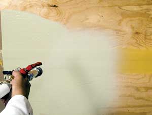
Figure 1b: Fluid
applied air/moisture barrier applied to sheathing
by spray application. |
|
|
When incorporating fluid applied air/moisture
barriers in wall assemblies, the following considerations
are important to effectively control condensation and prevent
moisture penetration:
Design Considerations
- Air permeability
- Continuity with other air barrier materials
- Structural integrity
- Durability
- Water penetration resistance
- Water vapor permeability
- Mechanical ventilation
- Construction details and sequencing
- Code compliance
- Climate
Air Permeability
The layers of material that make up a
wall assembly have different air permeability. Figure 2 provides
a comparison of typical materials used in wall assemblies
and their air permeability values.
Energy codes in the United States have
begun to require air tightness of the building envelope, but
they are not specific about levels of air permeability for
air barrier materials. The generally accepted level based
on National Building Code of Canada requirements is 0.02 L/(s·m2)
at 75 Pa pressure (0.004 cfm/ft2 at 1.57 psf). While many
common building materials like plywood and gypsum wallboard
meet this standard, a sheathed wall assembly will not perform
well as an air barrier unless the joints are treated with
an air barrier material. The sheathed wall assembly with treated
joints then becomes an air barrier sub-system of the total
building envelope air barrier system. The total building envelope
air barrier system consists of all the interconnected air
barrier materials-for example, treated wall sheathing,
roof membrane, foundation waterproofing, windows and doors,
and the air barrier connection materials between them.
Air Barrier Continuity
The overall design concept of air barriers in building construction
is the creation of a continuous airtight membrane around the
building envelope. Therefore, air barrier materials in wall
assemblies, to be effective, must be continuous. Breaks in
air barrier continuity cause air leaks. In cold climates the
breaks can allow significant amounts of warm moisture-laden
air to escape from the interior environment and condense on
a cold surface in the wall assembly. Conversely, in hot, humid
climates, breaks in the air barrier permit moisture-laden
air from the exterior environment to infiltrate the building
envelope and potentially condense on a cold surface in the
wall assembly. Any penetration through the wall assembly or
termination of the wall assembly must therefore be detailed
to maintain the continuity of the air barrier materials to
effectively create an air barrier system. Without continuity
of the air barrier materials in the wall assembly, air barrier
system performance is less effective. The design/construction
professional must take material compatibility and construction
sequencing into account when designing an airtight assembly
to ensure continuity. A number of connecting air barrier materials
exist that are compatible with fluid applied air/moisture
barriers to make transitions from one material to the next,
for example, rubberized asphalt membrane tapes to connect
from wall sheathing to foundation, or low-expanding urethane
foam sprays for use between windows and rough openings.
Air Barrier Structural Integrity
Structural integrity of air barriers is important because
wind loads are transferred to the most airtight components
in a wall assembly-the air barrier materials-and
in turn, are transferred to the structure. Negative and positive
wind loads stress air barrier materials. If the materials
tear or displace with loading, they lose their effectiveness
as air barriers. Some building wraps have low air permeability,
but they do not perform well when commonly installed because
they have many seams that reduce their effectiveness against
air leakage, and they are non-structural. If the seams in
building wraps are not taped, they do not perform well as
air barrier materials. Because building wraps are non−structural,
they are susceptible to displacement and tearing from negative
wind gusts in cavity wall construction. This compromises their
performance in service.1
Fluid applied air/moisture barriers are fully adhered. Adhesion
to sheathing exceeds the strength of the sheathing. Tensile
adhesion tests show that the paper or glass mat facing fails
in gypsum based sheathings, while unfaced sheathings like
plywood show adhesive failure at loads in excess of 344 kPa
(50 psi, could equate to more than a 2560 km/hr [1600 mph]
wind speed). The structural strength of the fluid applied
air/moisture barrier in effect equates to that of the sheathing.
Deformation while in service is limited to the deformation
of the sheathing. This means no tears and no compromise in
performance caused by structural loading, provided the sheathing
and supporting frame are adequate to resist loads.
Air Barrier Durability
While capable of resisting wind loads without compromise
in performance, air barrier materials must also demonstrate
durability in a number of other ways, particularly if the
air barrier is concealed and inaccessible for maintenance.
Durability criteria include:
- Resistance to puncture
- Resistance to pests-rodents, termites, carpenter
ants, and other insects
- Resistance to low but sustained negative pressures from
building stack effect and HVAC fan effect
- Ability to withstand stress from thermal and moisture
movement of building materials, and stress from building
creep
- Resistance to UV degradation (during the construction
period)
- Resistance to mold growth
- Resistance to abrasion
Fluid applied air/moisture barriers generally do not provide
a food source for insects or other pests. By virtue of their
excellent adhesion to sheathing and prepared concrete or masonry
substrates, they are resistant to puncture and they resist
loads imposed by stack effect and fan effect, as well as wind
loads. Their resistance to stresses imposed by thermal and
moisture movement, and building creep, is mainly dependent
on the ability of the joint treatment material to span gaps
in sheathing without cracking. This performance, in turn,
is dependent on the physical properties of the specific joint
treatment material. Similarly, the UV resistance, resistance
to mold growth, and abrasion resistance are dependent on the
physical properties of the joint treatment and waterproof
coating materials.
p class="mainboldBlue">Water Penetration Resistance
The traditional moisture protection used in wall construction
is asphalt-saturated felt or kraft waterproof building paper.
The terms weather-resistive barrier or moisture barrier are
often used to describe these components in wall construction.
They are generally installed over sheathing by lapping them
shingle-style and fastening with nails, screws or staples
to the sheathing. Their general purpose in walls is to protect
against ingress of incidental water into the building and
to protect moisture-sensitive components like gypsum sheathing
in the event of a breach in the outer wall covering, such
as a crack in stucco. Building wraps are often used in place
of asphalt felt in wall construction, often with the same
perceived purpose. The water resistance, air infiltration
resistance, and vapor permeability characteristics of building
wraps vary widely, depending on the brand of wrap selected.
(See references, PHRC Report No. 59). Seamless fluid applied
moisture protection provides a significant improvement over
traditional moisture protection and building wraps.In
fact, they can be 10 times more resistant to water penetration
than building wraps and nearly 200 times more resistant to
air leakage than asphalt felt .
Water Vapor Permeability
A fluid applied air/moisture barrier may or may not be a
vapor-retarding material. The generally accepted definition
of a vapor-retarding material is one that has a water vapor
permeance of 57.4 ng/(Pa·s·m2) [1.0 perms] or
less. In Table 1, the fluid applied air/moisture barrier components
are not vapor retarders. The joint treatment has a vapor permeance
of 994 ng/(Pa·s·m2) [17.3 perms] and the waterproof
coating has a vapor permeance of 327 ng/(Pa·s·m2)
[5.7 perms], about the same as Type 15 building felt.
| Building
Material |
Water
Vapor
Permeance
(Perma) |
Water
Vapor
Permeance
ng(Pa-s-m2) |
| 4
mil Polyethylene |
0.08
|
4.60 |
| 6
mm (1/4 inch) Plywood3 (ext glue) |
0.7
|
40.2 |
| 101mm
(4 inch) Brick3 |
0.8
|
46.0 |
| 203mm
(8 inch) Concrete Block3 |
2.4
|
138 |
| 25mm
(1 inch) Expanded Polystyrene1 |
5
|
287 |
| Type
15 Building Felt2 |
5.6
|
322 |
| Fluid
Applied Air Moisture Barrier Waterproof Coating |
5.7
|
327 |
| 19mm
(3/4 inch) Plaster on Metal Lath3 |
15
|
862 |
| Fluid
Applied Air Moisture Barrier Joint Treatment |
17.3
|
994 |
| 9.5mm
(3/8 inch) Gypsum Wallboard3 |
50 |
2873 |
Table
1: Water vapor permeance of fluid applied
air/moisture barrier materials
and common building materials. Check online
material for Table 1 notes. |
|
|
The purpose of a vapor retarder in wall construction is to
minimize water vapor diffusion through the wall assembly and
thus reduce the risk and the amount of condensation on cold
surfaces in the wall assembly. Whether or not a vapor retarder
should be placed in a wall assembly and where it should be
placed must be carefully evaluated in relation to climate,
the physical characteristics of other components of the wall
assembly, and interior relative humidity conditions. In cold
climates the predominant water vapor diffusion direction through
most of the year is from the inside to the outside, as warm,
humid air from the interior environment moves in the direction
of cold, dry outside air. Conversely, in hot, humid climates,
the predominant water vapor diffusion direction through most
of the year is from the warm, humid outside environment towards
the cooler, dryer, air-conditioned interior environment. Based
on these general conditions, a vapor retarder is customarily
placed on the interior of wall construction in cold climates
and on the exterior in hot, humid climates. A vapor retarder
should not be placed on the interior in hot, humid climates,
since it will potentially cause condensation by restricting
vapor diffusion to the interior. The use of interior vapor
retarders has been shown to be a contributing cause in many
cases of moisture problems and IAQ problems in buildings in
hot, humid climates. One tool that is available to assist
in making decisions about whether a vapor retarder is needed
and where to place it in the wall assembly is a water vapor
transmission analysis that can be performed manually (see
ASHRAE Handbook-Fundamentals, chapters 21 and 22) or
by computer (Trechsel, Moisture Analysis and Condensation
Control in Building Envelopes).
Mechanical Ventilation
A properly functioning air barrier system will limit the
influence of air infiltration and exfiltration on the heating
and cooling loads of the interior environment. This can increase
the efficiency of the HVAC system, which translates into energy
cost savings. However, the mechanical ventilation system must
still perform its basic functions of:
- Ventilation and exhaust
- Proper distribution of makeup air to interior spaces
- Dehumidification of air
- Filtration of outdoor air
Wind effects, stack effects, fan effects and space configuration
and partitions influence how the mechanical ventilation system
must be designed to perform adequately. ASHRAE handbooks provide
guidance on mechanical ventilation, and design and control
of interior relative humidity conditions to control microbial
growth, to minimize condensation potential, and to provide
occupant comfort, in relation to air leakage.

Figure 4: Fluid
applied air/moisture barrier lapped onto flashing
at the base of the wall to "splice"
the two materials and shed water onto the
flashing and to the exterior. |
|
|
Construction Details and Sequencing
"As much as 90 percent of all water intrusion problems
occur within one percent of the total building exterior surface
area. The one percent of the structure's façade
contains the terminations and transition detailing that all
too frequently lead to envelope failures."3
Construction detailing is a critical component for the success
of any wall assembly. The designer must create details that
effectively:
Control rain water penetration
that may occur via:
- Gravity flow-water that flows down and to the interior
if surfaces are sloped towards the interior, for example,
an improperly sloped brick ledge
- Kinetic energy-rainwater, for example, being blown
directly into large openings
- Capillary action-the tendency of water to travel
through narrow openings or cracks in materials toward dryer
surfaces, for example, a crack in a mortar joint
- Pressure differentials-the effects of wind pressure,
stack effect or mechanical ventilation that create pressure
differences across the building envelope, and drive water
through cracks or openings
Control condensation that
may occur via:

Figure 5: Integration
of the fluid applied air/moisture barrier
at the rough opening with interior air seal
and sill flashing beneath the window. |
|
|
The contractor must in turn coordinate and sequence work
so that details are properly constructed. Given that today's
buildings are generally "tighter" than they were
50 years ago, the importance of eliminating water intrusion
into wall assemblies increases substantially, since water
in walls may not readily dry. Some details are fundamental,
such as the proper sloping of sills and ledges to the exterior,
use of drip edges at soffit returns, capillary breaks in construction
joints, or lapping of the air/moisture barrier over flashing
at the base of a wall (Figure 4) to direct water to the exterior.
Other details are more complex, such as maintaining the continuity
of the air barrier at a window penetration (Figure 5) and
integrating the air/moisture barrier with sill flashing. Whatever
the detail, whether straightforward or complex in nature,
the development and execution of details is vital to the long
term success of the wall assembly, regardless of how well
the air/moisture barrier system performs. An important advantage
of a fluid applied air/moisture barrier in the wall assembly
is that it can mitigate or eliminate one of the major forces
that cause water infiltration into walls: pressure difference.
The fluid applied air/moisture barrier, in combination with
venting and compartmenting, can effectively enable the pressure
behind the cladding material to equalize with the pressure
outside, and prevent rain water penetration caused by pressure
differentials (pressure equalized rainscreen).
Code Compliance
United States
Model building codes and state and municipal codes in the
United States do not address air barriers, moisture barriers
and vapor retarders in a uniform way. Energy codes in the
United States, including the IECC (International Energy Conservation
Code), the State of Massachusetts Building Code, and ASHRAE's
1999 energy conservation standard (ANSI/ASHRAE/IESNA Standard
90.1-1999, Energy Standard for Buildings Except Low-Rise Residential
Buildings, an energy conservation standard which is required
to be adopted by state building energy codes under the Federal
Energy Conservation and Production Act) require air tightening
of the building envelope. Although codes in the United States
do not always provide specific limits for air leakage of air
barrier materials, the generally accepted limit is 0.02 L/(s·m2)
at 75 Pa pressure [0.004 cfm/ft2) at 1.57 psf)] based on National
Building Code of Canada requirements.
Most model codes generally require the
use of a water-resistive barrier in wall construction and
prescribe asphalt saturated felt (IBC Chapter 14, paragraph
1404.2). They often require the use of vapor retarders in
wall construction (IBC Chapter 14, paragraph 1403.3) unless
other means are provided to avoid condensation.
Fluid applied air/moisture barriers are
proprietary materials and are not listed in model codes. Provisions
are made for non-traditional building materials like building
wraps and fluid applied air/moisture barriers as an "alternate
material, design or method of construction."2 Approval
by the building official is based on his/her finding that
"….the intent of the provisions of the code [are
met]…and that it [the air/moisture barrier material]
is at least equivalent in quality, strength, effectiveness,
fire resistance, durability and safety to the materials or
methods of construction listed in the code."3 In practice
the building official cannot evaluate each and every new material
or method of construction, so model code evaluation agencies
do this for him/her and publish evaluation reports which describe
the use and limitations of alternate materials. Therefore
it is always important to verify compliance of a fluid applied
air/moisture barrier material with the code via an evaluation
report.
Southern Building Code Congress Public
Safety Testing and Evaluation Services, Inc. publishes an
Evaluation Guide on Floor, Wall, and Roof Systems (Testing
for Moisture Protection Barriers-SBCCI PST & ESI
Evaluation Guide 119), which lists specific performance criteria
for air and moisture barriers, including fluid applied air/moisture
barriers. Conformance with these criteria is the basis for
code recognition of fluid applied air/moisture barriers. ICBO
ES (International Conference of Building Officials, Inc.)
is similarly in the process of developing
a criteria for water-resistive coatings that function as alternates
to UBC (Uniform Building Code) prescribed weather-resistive
barriers.
Canada
The National Building Code of Canada requires an air barrier
system encompassing the entire building envelope, a vapor
barrier if condensation is expected, and control of precipitation
(Chapter 5, Environmental Separation, Sections 5.4-5.6).
Multiple standards are listed in the code that identify performance
requirements for building materials. New materials for which
a standard has not yet been written undergo technical evaluation
by CCMC (Canadian Construction Materials Centre), who publishes
evaluation reports which verify compliance of a material or
assembly with the intent of the code. Some air/moisture barrier
materials have been shown to meet the requirements for air
leakage as a material component of an air barrier system and
are either listed or currently under evaluation by CCMC.
Typical Wall Assemblies with Fluid Applied
Air/Moisture Barriers for Climate Zones in North America
The model wall constructions illustrated
below are examples of wall constructions that incorporate
a fluid applied air/moisture barrier in two climate zones
of North America. In each case the fluid applied air/moisture
barrier functions as an air barrier and moisture barrier material
over the sheathing that:
- Protects the sheathing from moisture damage during construction
- Minimizes air leakage into the wall cavity and to the
interior environment from warm humid outside air in hot
humid climates (and during summer months in cold climates)
- Protects the sheathing against incidental moisture that
may occur outboard of the sheathing but behind the cladding
while in service
- Minimizes air leakage from the interior towards the exterior
in cold climates
The fluid applied air/moisture barrier
has a unique advantage as compared to building wraps beneath
non-contact siding such as brick veneer with a cavity because
it is in effect structural and does not tear and lose its
effectiveness with negative wind gusts during construction
or while in service.
Note, in hot humid climates it is important
to:
- Use a water vapor permeable interior wall covering to
permit drying to the interior and to prevent condensation
immediately behind the interior wall covering.
- Use unfaced batt insulation to permit water vapor diffusion
and drying to the interior
- Pressurize the interior space with conditioned (dehumidified)
air so that warm humid outside air is not drawn to the interior
- Use a low permeance rigid insulation on the exterior to
resist vapor diffusion to the interior, especially if porous
cladding like brick veneer is used
Note that the rigid EPS insulation (as opposed to XEPS insulation)
is chosen because it is vapor permeable. The vertical grooves
in the insulation drain incidental moisture. The insulation
is adhesively attached to the fluid applied air/moisture barrier
to prevent thermal bridging that would occur if it was attached
with metal fasteners, and, to minimize penetration with mechanical
fasteners. The installation of the wood siding over strapping
creates a cavity to promote drying of the wood in the event
it gets wet during construction or while in service.
In cold climates the vapor retarder is
essential (unless mechanical controls are in place to adequately
control interior relative humidity conditions in winter).
The vapor retarder minimizes water vapor diffusion to the
exterior during winter months. However, it is essential to
eliminate leaks, condensation, or any other source of moisture
in the frame wall cavity, given that the vapor retarder on
the interior and the fluid applied air/moisture barrier and
insulation on the exterior create a very "tight"
construction with limited drying potential.
Note, in cold climates it is important
to:
- Insulate on the exterior, particularly when metal studs
are used, to prevent:
- Telegraphing (ghosting) of metal studs on the interior
or exterior wall surfaces
- Heat loss via conduction through the metal studs
- A dew point from occurring in the metal stud cavity
and condensation which can lead to corrosion
- Adjust the type and/or thickness of the rigid insulation
to prevent a dew point in the frame cavity and condensation
on or within the wall sheathing. As the size of the stud
cavity increases and the thickness of batt insulation increases
the dew point moves further to the exterior with the risk
of the sheathing becoming a condensing surface.
- Provide a neutral or slightly negative indoor pressure
to prevent exfiltration of warm humid air into cold walls
Note that each of the above model wall
constructions illustrates a design strategy that incorporates
a fluid applied air/moisture barrier, and other design considerations
for the effective control of moisture in the wall assembly.
As each building is different and has its own unique set of
materials, climate, and interior conditions to consider, these
model wall assemblies should be taken as a guide relative
to any specific project. Appropriate adjustments in materials,
and their position in the assembly should be made. The overall
design strategy must include prevention and control of rain
water penetration, minimizing the risk of condensation caused
by water vapor diffusion or air leakage, and maintaining proper
mechanical controls of the interior environment.
Fluid applied air/moisture barrier materials
are effective components in wall assemblies that control moisture
by minimizing air leakage and protecting water-sensitive components
from moisture. Their material properties such as water vapor
permeability, UV resistance and mold resistance must be taken
into account. They are cost effective alternatives for moisture
control in wall assemblies that have several performance advantages
over building wraps and traditional asphalt saturated felt
or paper moisture protection.
Table 1 Notes:
- Dry Cup Method
- Wet-Cup Method
- Other Method
- Note: this chart provided for information only. Direct
comparisons of water vapor permeance values may not always
be applicable, as different methods of measuring produce
different results. Materials may also have varying water
vapor permeability with changes in relative humidity.
- Sources of Data: ASHRAE Handbook Fundamentals and Sto
Corp.
Figure 3 Notes:
- Source of Data: independent testing by Cerny & Ivey
Engineers
- Fluid applied air/moisture barrier material did not leak,
but met limit of testing fixture.
- Materials tested in accordance with AATCC-127 (American
Association of Textile Chemists and Colorists Test Method
127−Water Resistance: Hydrostatic Pressure Test [modified]).
A column of water 55 cm (21. 6 inches) tall is placed over
the moisture barrier material and sealed to the surface.
The moisture barrier material spans a 3 mm (1/8 inch) wide
joint in supporting sheathing. Building wraps and building
paper are not penetrated with fasteners. Time to water penetration
is then measured. For the materials that met the 5 hour
criteria, the height of the water column was increased to
determine the limits of the material.
References
American Architectural Manufacturers
Association, Installation Masters Training Manual. Schaumburg:
AAMA, 2000.
American Architectural Manufacturers
Association, Window Selection Guide. Palatine: AAMA, 1995.
American Association of Textile Chemists
and Colorists, AATCC-127 Water Resistance Hydrostatic Pressure
Test. AATCC, 1995.
American Society of Heating, Refrigerating
and Air-Conditioning Engineers, Inc., 1993 ASHRAE Handbook-Fundamentals,
(I-P Edition), Atlanta: ASHRAE, 1993.
Anastasi, Leonard, "Air Barrier
Systems for the Life or Your Building," The Construction
Specifier, (March, 2002), 30−35.
Anis, Wagdy "Insulation Strategies
for Exterior Walls," The Construction Specifier, (August,
2002), 40−45.
Canada Mortgage and Housing Corporation,
Commissioning and Monitoring the Building Envelope for Air
Leakage, (Report No. 33127/02), Ottawa: CMHC, 1993.
Canada Mortgage and Housing Corporation,
Rainscreen, Ottawa: CMHC.
Cerny & Ivey Engineers, Inc., Water
Penetration Resistance Testing Sto Gold Guard (Engineering
Report No. 20409), Atlanta: Cerny & Ivey Engineers, Inc.,
2001.
International Code Council, Codes Forum(September/October),
Falls Church: ICC, 2002.
Construction Specifications Canada and
Alberta Building Envelope Council, CSC TEK·AID Digest
Air Barriers, Toronto: CSC & ABEC, 1990.
Foundation of the Wall and Ceiling Industries,
Mold: Cause, Effect and Response, Itasca: FWCI, 2002.
International Code Council, Inc., International
Building Code. Falls Church: ICC, Inc., 2000.
International Conference of Building
Officials, Uniform Building Code, (Vol. 3), Whittier: ICBO,
1997.
Kubal, Michael, T., Waterproofing the
Building Envelope, New York: McGraw-Hill, Inc., 1993.
Lstiburek, Joseph. Builder's Guide.
Minneapolis: Energy and Environmental Building Association,
2001.
National Research Council of Canada,
National Building Code. Ottawa: NRCC, 1995.
Southern Building Code Congress International
Product Safety Testing Evaluation Services, Inc., Evaluation
Guide on Floor, Wall, and Roof Systems (Testing for Moisture
Protection Barriers). Birmingham: SBCCI PST & ESI, 1995.
Odom, David J. III, Preventing Indoor
Air Quality Problems in Educational Facilities: Guidelines
for Hot, Humid Climates, Orlando, 1997.
Odom, David J. III, "Solving Indoor
Air Quality Problems in Hot, Humid Climates," Building
Standards (September-October, 1994), Whittier: International
Conference of Building Officials, 1994.
Pennsylvania Housing Research Center,
The Use of Housewrap in Walls: Installation, Performance and
Implications, (PHRC Research Series Report No. 59), University
Park: PHRC, 1998.
Trechsel, Heinz R., Moisture Analysis
and Condensation Control in Building Envelopes, (ASTM MNL40),
West Conshohocken: ASTM, 2001.
Footnotes
- The Use of Housewrap in Walls: Installation, Performance
and Implications, PHRC Research Series Report No. 59 (University
Park, 1998), p. 41.
- International Code Council, Inc., International Building
Code (Falls Church, 2000), p. 3.
- Ibid.