This CE Center article is no longer eligible for receiving credits.
Providing sustainable, energy-efficient lighting systems, while maintaining performance and aesthetically pleasing forms, is sure to be one of the greatest challenges for architects and design professionals in the 21st century.
 Global attention to climate change and environmental disasters, such as "The Gulf Oil Spill," has intensified the spotlight on environmentally conscious design and the use of renewable energies. According to the U.S. Department of Energy (DOE), residential and commercial buildings consume more than one third of the energy used in the United States each year. Lighting for commercial buildings accounts for 25 percent of this energy usage. LEED, ASHRAE/IESNA 90.1 and California Title 24 have helped drive design professionals to respond with innovative solutions to achieve their design intent. Manufacturers are challenged with providing energy-efficient and environmentally friendly products to meet market demands while evaluating their own carbon footprint in the process.
Photovoltaics (PV) is a solar energy technology that uses semi-conductors to directly convert solar radiation to electricity. Charge controlled stand-alone PV exterior lighting systems will be discussed to provide the knowledge needed to successfully specify and apply this new technology.
Benefits of Using Solar-Powered Lighting
Cost savings. The decreasing cost of PV modules and increasing costs of electricity only strengthen the existing benefits of using solar-powered lighting. Possibly the greatest benefit of solar lightng is the ability of the system to operate without the presence of an electrical infrastructure. As the distance from a project site to a source of electricity increases, the time it will take to pay off a solar-powered lighting system will decrease. In addition to eliminating the need to trench, backfill and route conduit and wire, electrical distribution equipment such as transformers, circuit breakers and controls are no longer needed, and therefore a solar lighting system requires less man hours to install compared to traditional lighting systems. Not having to verify underground utilities, obtain electrical permits or schedule electrical inspections simplifies project coordination. Along with the above mentioned cost savings, an owner or municipality will not pay an electricity bill for the life of the system.
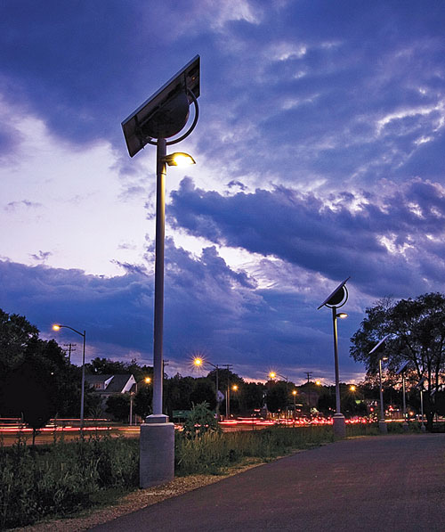 |
Solar lighting extends usability of a popular bike path in Madison, WI.
Photo: SELUX Corp. |
Convenience/flexibility. Installing traditional electric lighting in sensitive project sites with existing hardscape and landscape features may be prohibitive due to the high cost of restoring the site to its original condition (e.g., memorial sites, registered historic landmarks, and areas densely packed with underground utilities). Examples like this point out how off grid solar lighting can add convenience when lighting is required, even if electricity is present on site. Another convenience may be realized during utility power outages. The off-grid lighting will continue to operate allowing the owner of the system to experience first hand the benefits of their investment at work.
Environmental impact. Design professionals and owners who want to minimize their impact on the natural environment have plenty of reasons to go solar. Using a renewable energy source, such as the sun, to power lighting eliminates the need to burn additional fossil fuels for power generation and reduces the production of carbon dioxide released into the atmosphere. Solar lighting systems by design are sustainable long-life products. Most solar panel manufacturers offer warranties on power output of their modules from 15 to 25 years. For this reason solar-powered lighting manufactures attempt to engineer systems with components and finishes that will perform as long as possible. Low wattage optimized lighting distribution ensures that every lumen generated by the lamp is directed to the specific task at hand. This affects the environment by preventing any stray light from polluting the night sky, reducing light trespass onto neighboring properties and controlling high angle brightness to improve visual comfort
and performance.
 |
Innovative design for a large parking facility in AL
Photo: SELUX Corp. |
Â
Meeting design guidelines and energy codes. Today, design professionals are often required to meet strict Lighting Power Densities for exterior lighting as outlined in ASHRAE/IESNA 90.1. This is a clear advantage for solar lighting which uses zero watts per square foot of utility electric. Lighting performance criteria is usually outlined in some form by ordinance, code or guideline. Light output and distribution of solar-powered luminaires today have the ability to meet challenging criteria being enforced by project mandates and municipalities.
Components Used in Off-Grid Solar-Powered Luminaires
All off-grid solar-powered lighting systems use five basic parts including a charge controller, battery, panel, luminaire and balance of system (BOS). Miscellaneous parts such as wiring, pole, enclosure, mounting, etc. are all included in the BOS.
Charge controller. The charge controller is a critical component of an off grid solar lighting system. Some of the key tasks of a charge controller are to regulate battery charge from the PV modules, maintain the batteries at their highest state of charge and prevent overcharging or over discharging. All of these features help to maximize the battery performance and life. Charge controllers with load control also manage energy flow between modules, batteries and the load. In this case, the load is the luminaire which can be programmed to operate on a specific time schedule (e.g., a luminaire may turn on for 8 hours after sunset, turn off for 4 hours and then turn on again until sunrise). The latest innovations in charge controller technology are Maximum Power Point Tracking (MPPT) and Pulse Width Modulation (PWM). Voltage and current produced by a PV module change independently depending on temperature and irradiance conditions. Irradiance refers to the intensity of available solar resource. MPPT controllers use electronics to increase the total watts produced by taking advantage of the maximum voltage and current values generated by the module during actual operating conditions. Colder climates tend to see the largest boost in performance by this technology with efficiency increases up to 30 percent. PWM is a technology that can be used for battery charging or switching LED-based lighting. The technology switches a series device on and off at a high frequency and for variable lengths of time. PWM charging can maintain a higher battery state of charge and increase the life of the battery. A PWM output can cycle LEDs on and off at such high frequencies that no visual change is noticed while energy consumption is reduced.
Batteries. Valve Regulated Lead Acid (VRLA) deep-cycle batteries are the most common battery technology used in PV systems. Gel and Absorbed Glass Matt (AGM) are both VRLA batteries commonly used for their many advantages. These batteries have the ability to handle deep discharge cycles and have low self discharge rates. They are also fast to recharge, require no maintenance and have low to no off gassing. Being of the non-spill and low off-gassing type allows Gel and AGM batteries to be transported by air; a big advantage for distribution. Operating temperature of a battery affects the internal resistance and its ability to hold a charge. A multiplier can be applied to batteries operating at temperatures below 80 °F to determine reduced capacity. The capacity of a battery is measured in Amp-hours (Ah) and is typically specified at a 20-hour rate. This means a battery with a 100Ah capacity will operate at a discharge rate of 5 Amps for 20 hours. (5A x 20h = 100Ah). If the battery is operated at a higher discharge rate, it will produce less than the rated capacity. For example, a 100Ah battery operated at a 10-hour rate (10A) will produce approximately 60Ah of capacity. Warranties offered for some VRLA Gel and AGM batteries can range up to five years, but years can be added to the overall life when operating conditions are favorable.
Panels. PV modules typically utilize one of three main cell technologies, mono-crystalline, poly-crystalline and ribbon silicon. These cell types convert solar radiation to electricity with an efficiency of approximately 11 percent to 18 percent. Efficiency and cost tend to go up together and forces other factors such as available area and application of the module to determine which technology should be used. Mono-crystalline modules offer the highest efficiency at 14 percent to 18 percent but also have the highest manufacturing cost. Poly-crystalline modules are 11.5 percent to 14 percent efficient and they tend to have the best balance of cost, efficiency and size. Ribbon silicon otherwise known as amorphous thin film has the lowest efficiency at 11 percent to 13 percent and requires a larger area to produce the same amount of power versus mono-crystalline and poly-crystalline. Amorphous thin film does however have some unique performance advantages making it desirable for specific applications such as when primarily diffuse sun light is available. Utilizing diffuse sunlight better allows this cell technology to tolerate shading and produce more power from early morning and late day sunlight. New technologies such as bi-facial cells and total internal reflection modules are being developed but have not been studied in practice long enough to break into the mainstream.
Luminaire. In order to make the most of the power generated by the power source an efficient and effective luminaire must be used. A luminaire is a light fixture complete with a lamp, voltage regulator (electronic ballast), luminous opening with or without a lens and a connection to a power source.
 |
Solar lighting as an architectural form
Photo: SELUX Corp. |
Balance of System (BOS). Electrical and structural components, aside from the major components make up the Balance of System. Mounting rack for solar panels, housing of the batteries, pole and all inter-wiring are examples of the BOS for an off grid solar lighting unit. Quality of these parts is important to the overall life of the system. Aesthetics are also dependant on the parts and pieces selected to integrate the major components into a single package. Currently available systems range from very basic raw parts and pieces to architecturally attractive forms.
Explanation of Lighting Metrics |
Term |
Basic Explanation |
Measurement |
Luminous Flux |
Amount of light emitted
in all directions |
lumens (lm) |
Luminous Intensity |
Intensity of light
in a specific direction |
candelas (cd) |
Illuminance |
Total luminous flux incident
on a surface |
 lux or footcandles |
Luminance |
Amount of light reaching the eye after reflecting off a surface. |
candelas/m squared |
Source: IESNA Lighting Handbook, 9th Edition |
Â
Choosing the Right Luminaire
Identify the lighting needs. With the cost of solar lighting systems ranging widely depending on size, it is best to identify how much light is really needed for an application. In addition to the quantity of light, the amount of hours the system must provide a specific light level each night has a big impact on system size and, therefore, cost. Review the use of your project site; will there be pedestrian activity all hours of the night, or only until a certain time? If lighting can be dimmed or turned off after that time the size and cost of the system will decrease. If security is a concern and illuminance must be maintained at a high level from dusk until dawn the system size and cost may increase significantly. Attention to these considerations when specifying solar lighting will ensure that the owner of the system pays for only the performance that the project will require.
 In 1997 the Commission Internationale de l'Eclairage (CIE) defined lighting zones that would typically have different lighting requirements. The IESNA and LEED rating system have both adopted this method of classifying a project site into one of four zones. Environmental Zones E1 − E4 provide descriptions of each zone and recommended maximum illuminance levels for each.
Environmental Zone E1, for example, is described as an area that is intrinsically dark, such as a park or residential area where controlling light pollution is a high priority. Areas classified as E1 will allow lower maximum illuminance levels compared to a project site classified as an environmental zone E2, E3, E4. Environmental Zone E4 allows the highest maximum illuminance levels and is described as areas of high ambient brightness such as an urban environment or areas experiencing high levels of nighttime activity (Source: IESNA − RP-33-99 Lighting for the Exterior Environment).
Recommended illuminance levels, uniformity levels and other important lighting criteria are published by the Illuminating Engineering Society of North America. This is a good basis for selecting illuminance levels if no lighting criteria are specified by the local municipality or project.
Choosing a light source. Choosing the best light source or lamp type for an application has an impact on security, maintenance, public acceptance and aesthetics. At night this is the component of the system that will receive the most attention, positive or negative. Some lamp types used in solar lighting are Compact Fluorescent (CFL), Induction Lamps, High Pressure Sodium (HPS), Metal Halide (MH) and Light Emitting Diodes (LED). LED sources will be discussed in more detail when we compare LED luminaires to luminaires using traditional lamping.
Key lamp characteristics for solar lighting are Lamp Efficacy, Correlated Color Temperature (CCT), Color Rendering Index (CRI), Rated Life and Lumen Maintenance. Lamp efficacy in basic terms is how many lumens are produced by a lamp divided by the wattage used to operate that lamp. Correlated Color Temperature is stated as degrees Kelvin and generally describes the hue of the light. Incandescent lamps have a CCT value of 2700K (warm reds-yellows-pinks) and natural daylight is more in the range of 6500K (cool blues-whites). CRI uses a scale 1 to 100 and rates the ability of a light source to render color of an object faithfully compared to a full spectrum natural light source. Rated Life is determined by testing a group of lamps under specified conditions until 50 percent of the lamps burn out. This is considered the average rated life of the lamp. Lumen Maintenance varies by source type; all light sources have depreciation in light output over time. By dividing the mean lumens of a lamp (output at mean life of lamp) by the initial lumens you can determine the lamp lumen depreciation for that source. Now that we know which lamp characteristics are most important to compare we can begin to analyze the different sources to see where they may be best applied. The information below is based on specific lamps and generally represents the performance of their group.
At the top of the lamp comparison chart we see information for a Metal Halide T6 lamp. T6 is a small, point source type of Metal Halide lamp. The small burner or "point source" of the T6 lamp is easier to control than a larger diffuse source which allows for a more precise distribution. Ranked highest for its superb CRI value the Metal Halide T6 lamp provides accurate color representation which can be an advantage when security is a concern or when crisp accurate color is your priority. Efficacy of this lamp is also something to note. It is producing more lumens per watt than any other lamp group, making it a great match for use with a solar lighting system when every watt counts. Metal Halide T6 lamps do not respond well to dimming. This lamp type also has the shortest life at about 3 years if operated for an average of 12 hours per day, per year.
The next lamp group in our chart is the Compact Fluorescent Lamp (CFL). Once scrutinized during early commercialization, Compact Fluorescent lamps have improved dramatically and are now well accepted by the public and design professionals alike. A good balance of lumen maintenance, color, efficacy and life make the CFL a good choice for a variety of applications. Compact Fluorescent lamps do go through a warm up period to reach full brightness and color stability. This will be more noticeable in cold climates.
Light Source Technology Comparison |
Lamp Group |
Watts |
Initial Lumens |
Lumen Maintenance |
CCT |
CRI |
Efficacy |
Life |
Metal Halide (T6) |
39 |
3300 |
80% |
4200K |
90 |
85 |
12,000 |
CFL |
32 |
2400 |
85% |
4200K |
82 |
75 |
16,000 |
Induction |
55 |
3500 |
80% |
4000K |
80 |
64 |
100,000 |
HPS |
35 |
2250 |
90% |
2100K |
21 |
64 |
24,000 |
LED * |
N/A |
N/A |
85% |
5000K |
82 |
64 |
50,000 |
Source: SELUX Corporation
* Installed performance of typical LED light engine |
Â
Induction lamps are less commonly used but certainly have their place for specific applications. The large diffuse source and associated generator can provide an impressive 100,000 hours of operation. Best applications for induction lamps are areas difficult to access or areas that demand the longest possible operating life. Color, efficacy and lumen maintenance are all adequate for most exterior lighting environments. The size of the lamp and generator make these lamps difficult to integrate into small forms and precision optical systems.
High Pressure Sodium (HPS) lamps are commonly used in street lighting for their excellent lumen maintenance and long life. This lamp group is easy to identify at night due to the pinkish color of light and low color rendering abilities. These attributes can make it difficult to identify approaching people or even your car in a parking lot. For these reasons HPS lamps should not be used when security is the overriding factor of a project.
Light Emitting Diodes (LED) as a technology is not new, but the use of LEDs in commercial and residential lighting is. Similar to the introduction and commercialization of compact fluorescent lamps, there is a learning curve taking place for consumers, specifiers and manufacturers. Testing procedures and standards for LED lighting are still being created and adjusted as research continues and performance improves. Being an electronics-based technology much of the lighting world has had to retrain staff and gather new skill sets to become experts in the field. Such excitement about the technology has influenced many to make the leap to LED lighting without doing their homework. There is a wide variety of quality in LED lamps and luminaires available today. Due to varying quality, exaggerated claims and the fear that public acceptance may be harmed has spurred the U.S. Department of Energy (DOE) and the Next Generation Lighting Industry Alliance (NGLIA) to create the Lighting Facts Program. Lighting Facts is a voluntary pledge program to assure that LED lighting products are represented accurately in the market. The program requires submission of independent testing results from certified labs; upon approval the certified specifications are compiled into a label that can be used for marketing purposes. Having the label will not only provide vital performance information but will also allow the consumer to be confident that they are getting the performance claimed. Comparing solar lighting systems involves understanding performance and distribution of the luminaire, quality of components, as well as achievable runtimes and light levels. As with many technical products it is wise to consult with manufacturers to get answers to these questions in order to make the most appropriate selection for a project and ensure successful implementation of the technology.
 |
Installers complete an installation at Fairmont Park, PA.
Photo: SELUX Corp. |
Â
Comparing LED and traditional luminaires. An LED is an electronic semiconductor device and differs greatly from traditional light sources. Therefore new methods of testing and comparing LED sources and luminaires are necessary. Performance of a single LED or an array of LEDs packaged as a "light engine" is greatly affected by heat. For this reason, performance of an LED light engine will change a great deal when incorporated into a luminaire or form. The ability of the luminaire to remove heat from the LEDs through conduction/convection is critical. High temperatures inside the fixture can significantly reduce the light output and life of the LEDs. Absolute photometry is a testing procedure recently established by the IESNA to provide a more appropriate way to measure LED lighting distribution and output. The absolute photometry method measures overall lumens delivered and power consumed by the LED luminaire under given standard testing conditions. This method does not consider the specified lumens or watts of each individual LED since these values change with environment. Instead the luminaire is evaluated as a complete package. Testing of traditional luminaires has been done following the relative photometry method. With relative photometry the lamp in a given position can be accurately measured outside of the fixture. Since the lamp performance will not vary much when installed, the fixture and lamp can now be tested together to determine how many lumens the optical system emitted from the housing relative to the total lamp lumens. This is referred to as the luminaire efficiency. When you compare LED and traditional luminaires, be sure you are comparing apples to apples or in this case, delivered lumens to delivered lumens. Specifications of the individual LEDs are more relevant to an engineer designing the luminaire than a specifier or customer reviewing the final product.
Vision and color. Many studies have been done on how the human eye performs to different light levels and colors. Photopic vision uses cones of the eye and is generally referred to as "day" vision or vision under high illuminance levels with good color perception. Photopic vision is the basis for the development of light level criteria published by the IESNA. Even illuminance meters measure light based on a photopic response. Scotopic vision utilizes rods of the eye and is generally referred to as "night" vision. Scotopic vision like that of someone under a moonlit sky will have poor visual acuity and color perception. To evaluate human vision in conditions such as exterior night time lighting where light levels are higher than that of scotopic but less than photopic levels a third category is used. Mesopic or "dim light" vision uses both rods and cones. Studies have found that the spectral distribution of a light source can affect the perceived brightness of a space. Correlated color temperatures of 5000K to 6500K or higher (more bluish-white light) will be perceived as brighter because of the additional engagement of rods in the eye. In effect, identical streetscapes could be lit to the same illuminance levels with one site having a more scotopically rich color spectrum; in this scenario the scotopically rich site will always appear brighter. This concept is especially relevant to LED sources which are more efficient in higher CCT ranges.
Luminaire performance.Regardless of the light source technology used in a luminaire, all luminaires can be evaluated by the horizontal pattern of light (lateral distribution) and by the amount of light in vertical angles. A plan view of the lateral light distribution or pattern of light on a task plane can be organized into five main groups. Established by the IESNA and represented by roman numerals Type I through Type V, these distribution classifications give designers a quick idea of what the pattern of light from a luminaire will look like. For example a Type I distribution may provide the best distribution for a narrow bike path where a Type V distribution would be best suited for luminaires mounted in the middle of a large open parking area.
In addition to lateral distribution, in 2007 the IESNA revised the previous cut off classification groups that defined the amount of light in vertical angles. Luminaires once classified as full cut-off, cut-off, semi cut-off and non cut-off now use the Luminaire Classification System (LCS) published in the IESNA TM-15-07 document.
The Luminaire Classification System (LCS) defines distribution of light from a luminaire within three primary solid angles: back-light, up-light and front-light. These three primary angles are further divided into 10 secondary solid angles. The secondary angles are described as back-low (BL), back-mid (BM), back-high (BH), back-very high (BVH), up-low (UL), up-high (UH), front-low (FL), front-mid (FM), front-high (FH) and front very-high (FVH). The new LCS system allows for a much more detailed evaluation compared to the old system. This is beneficial to designers evaluating the environmental impact of a luminaire and will provide key data about light spill, light pollution and glare.
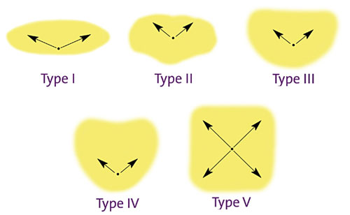 |
Example of lateral distribution types for exterior luminaires
Source: IESNA Light Distribution Patterns RP-33-99 |
Â
The LCS added a back-light, up-light and glare rating system, otherwise known as BUG. The BUG rating system provides a rating of 0-5 which describes how much of the luminaire lumens are present in each solid angle. For example, B1-U3-G1 describes a luminaire with very minimal back-light, moderate up-light and very low glare. This BUG rating system provides designers with a quick indicator of a luminaires vertical distribution performance. A quality solar luminaire should have good control of light to make the most of the lumens produced without creating glare.
Another relevant item to compare when evaluating luminaires is the amount of lumens delivered. Delivered lumens refer to the total amount of lumens exiting a luminaire. Total input wattage, which considers the total watts consumed by the ballast or power supply, can be used when comparing two luminaires with a known delivered lumen value to identify how many delivered lumens are being produced for the amount of watts consumed. An example of this would be a luminaire delivering 3400 lumens and consuming 44 total watts would relate to 77.3 lumens per watt. Lumens per watt can be referred to as the efficacy of the luminaire; more lumens per watt is good. However, it is important not to use this as the only metric in which to compare luminaire performance because where and how the light is distributed is equally important.
 |
LCS Example showing three primary angles for back-light, up-light and forward-light (yellow, blue & green) and ten secondary angles used to evaluate luminaire distribution in more detail
Source: IESNA Luminaire Classification System TM-15-07 |
Â
System Sizing
To provide some additional insight into how systems are sized we will cover the effects of location and the basics of how panels and batteries are sized. PV systems can be sized by hand or with the use of a developed spreadsheet or computer software. All methods take into consideration the specific location of the site.
Location. Every location on Earth experiences an average of 12 hours of darkness per day for a year, but the actual number of hours of darkness on any particular day of the year varies from place to place. Locations around Earth's equator receive about 12 hours of darkness each day. In contrast, the North Pole receives 24 hours of darkness for a few months in winter. PV panels and batteries must be sized for a specific geographic location since the amount of time the system may need to operate fluctuates. System sizing based on a specific geographic location is necessary since the amount of available solar resource also fluctuates from place to place.
Peak sun hours is an equivalent measure of total solar irradiation in a day, 1 peak sun hour = 1,000w/m2 (e.g., a day with average irradiance of 600 W/m2 over 8 hours may only reach peak sun around noon for an hour or less. The total irradiation of 4800 Wh/m2 is equivalent to 4.8 peak sun hours). Solar radiation data sets include the amount of solar energy that strikes a surface at a particular location and time on earth. These data sets are based on 30 years of collected data. Organizations such as the National Renewable Energy Laboratories (NREL) as well as others make these data sets available. Data sets are based on peak sun hours average/max/min for a given month or year. They also consider tracking systems and array tilt angles.
The chart that follows is an example of a data set for a specific latitude and longitude in upstate New York. Locations with more peak sun hours can be described as receiving more solar radiation. Availability of solar radiation at a given site will impact system size. Peak sun hour maps show generally how many peak sun hours average for a year are available in different locations of North America or the world. The amount of available solar radiation can differ greatly even within a small geographic area. For example, the state of Texas ranges from 3.3PSH in the east to 5.0PSH in the west of the state.
Determining the optimal tilt angle of the panels for an off grid system differs from a grid tie system. Grid tied systems are most concerned with the maximum average irradiation for the year. Off grid systems are most concerned with optimizing tilt angle to achieve the highest minimum irradiation value during the critical design month. For an off grid system, the critical design month refers to the month with the lowest available radiation levels and subsequently the longest nights. Panel tilt angles for off grid systems that will operate all year long will not benefit by an adjustable tilt angle. Typical off grid systems are sized for the critical design month. For example, December would be the critical design month for someplace like New York State, which has a latitude of about 45 degrees north. In order to optimize power production it is necessary to keep the angle of sunlight perpendicular to the panel. In winter with the sun path being much lower in the sky, using a tilt angle +15 degrees of your latitude will produce the maximum amount of power possible. Having a 60 degree tilt angle in the summer is not optimal, but summer provides more peak sun hours so an optimal tilt angle is not necessary. Once batteries are charged no use can be made of the extra power. Panel orientation is not as critical but typically face due south in the northern hemisphere and due north in the southern hemisphere. When locating your solar luminaires, on site obstructions of panels from sunlight should always be considered. Shading (even partial) of PV modules/arrays can cause disproportional reductions in power output. For this reason it is important to be aware of shading from buildings, trees and other obstructions.
How the Solar Resource is Quantified |
Solar resource |
Basic explanation |
Measurement |
Solar Irradiance |
The intensity of solar power |
Watts per square meter (W/m2) |
Solar Irradiation |
The total amount of solar energy accumulated on an area over time |
Units of watt hours per square meter (Wh/m2) |
Source: Photovoltaic Systems 2007 |
Â
At a minimum, three pieces of information are required to size a solar lighting system. First and foremost is the location of the site, as described previously. In addition to location, the total input watts of the luminaire including driver or ballast must be known. Finally, the hours per day the luminaire will operate "run time" is defined. Based on these three pieces of information, a system sizing can be done. Although the site location of an installation is a fixed item, luminaire wattage and hours of run time are variables. By adjusting these variables, different size options of panels and batteries may be possible. Whether the emphasis is reduced cost or maximum run time, the system can be adjusted to accommodate specific needs. Another important factor to review when sizing batteries is the quantity of autonomy days required. Days of autonomy refers to the amount of reserve days the battery bank will operate the luminaire without sun. Days of autonomy typically range from three to five days but really depend on location. Certain regions experience more overcast days than others. Seattle, WA, for example, typically experiences a fair amount of overcast conditions and would require more days of autonomy than a location such as Phoenix, AZ, which is known for its sunny weather.
Click on the image to veiw larger details
 |
Source: Solar Radiation Data Set, National Renewable Energy Laboratories |
 |
Available solar resource in Peak Sun Hours for the United States during winter
Source: Solar Insolation Map, U.S. Department of Energy |
Applications for Off-Grid Solar Lighting
Off-grid solar lighting has emerged as a reliable means of providing effective, creative and sustainable lighting solutions for a variety
of applications.
National, state or municipal parks are applications where solar lighting systems have many advantages over traditional lighting systems. Parks typically have trails, facilities, parking areas and roads that require low-level lighting without an extensive electrical infrastructure in place to support this need. In these cases, solar lighting is an appropriate solution and also contributes to the preservation of the environments being lighted. Beach and marina applications often benefit from the less invasive installation process of solar lighting which provides a cost effective option with minimal impact to the site. Test labs for government agencies, backcountry weather observatories and military training facilities that require exterior lighting are usually located in remote areas where extending utility power is not an option. Many third world countries have unreliable power or no power at all. After natural disasters the ability to provide immediate exterior lighting can be extremely beneficial allowing continued recovery efforts and added security. The ease, reliability and independence of solar power make lighting these types of facilities and locations possible.
Providing environmentally friendly lighting that utilizes renewable energy is undoubtedly a beneficial scenario for both planet and people. As technology evolves and hybrid systems utilizing wind power, solar power, axis tracking and LEDs become available, the future for renewable energy lighting systems is brighter than ever.
Â
 |
SELUX offers a comprehensive range of high quality architectural interior and exterior light fixtures, including solar powered and dark-sky certified fixtures. Innovative luminaires designed to help lighting professionals and architects create exceptional interior and exterior spaces in which to live and work.
http://www.selux.com/usa |
|