This CE Center article is no longer eligible for receiving credits.
Optimum Insulation
The other important driver for CI becoming more mainstream as a building practice was economics and the concept of “optimum insulation.”
Although it requires an initial increased investment during construction, insulation creates reduced energy costs for the life of the building. The question then becomes, “how much insulation is enough?” “What is the optimum amount of insulation?”
“Optimum insulation” is the amount of insulation that has the lowest life cycle cost (LCC). LCC is expressed as:
LCC = FC+M+R+E – RV
LCC = Life Cycle Cost ($)
FC = First Cost ($)
M = Maintenance and repair cost ($)
R = Replacement Cost ($)
E = Energy Cost ($)
RV = Resale value or salvage ($)
The concept of determining the lowest life cycle cost (LCC) is illustrated in Figure 2.

Figure 2: Life Cycle Cost Analysis
In addition to adhering to the public policy principles of the 2030 Challenge and the MOU with DOE, the ASHRAE 90.1 standard committee also justifies insulation levels using sound economic principles.
Figure 2 illustrates the concept showing first cost for insulation/construction increasing as R-value increases. The principle is obvious, as one installs more insulation, the first cost of insulation increases. Equally obvious it captures energy cost and consumption decreasing as R-value increases.
The LCC is the lowest sum of “first cost” and “energy cost” at a given level of R-value. In this hypothetical example, R-20 is the lowest LCC, and, is therefore the “optimum insulation” level. Figure 2 only demonstrates the concept of “optimum insulation.”
Actual optimum levels must be calculated for specific climates, specific building construction types, specific building usage patterns and specific economic assumptions regarding construction and energy costs. The concept of Life Cycle Cost Analysis and Optimum Insulation are utilized by ASHRAE in the development of Standard 90.1 however it is a minimum standard that sometimes lags behind the upward trend of energy and construction costs, particularly when a building built today will have a useful life several decades into the future. Therefore, the path to raising awareness and increasing energy standards to include the use of CI was aligned with economic and public policy through the early 2000’s.
Performance Benefits Resulting From the Use of CI
The location of continuous insulation is determined by the type of construction, climate zone, building function and ease of construction. CI may be integrated as part of many common wall designs including steel framed and masonry cavity walls, rainscreens and rain barriers, pre-cast and tilt-up concrete panels. It can also be incorporated behind many types of cladding including architectural metal, masonry, stucco and EIFS. Generally, it is easiest to construct continuous insulation on the outboard side of the wall framing to minimize complex detailing around floor lines, exterior penetrations and openings.
When located on the outboard side of the wall, CI achieves two things: 1) it keeps the wall framing warmer, meaning it is closer to the building’s interior temperature, and, 2) the added CI R-value shifts the dew point, to the point that it often is located outside of the framing cavity insulation. Minimizing condensation inside walls reduces the likelihood of moisture accumulation which decreases the possibility of structural corrosion and decay and the opportunity for mold and mildew to develop.
Unfortunately, structural components (concrete masonry units, steel studs, wood studs and concrete) are better conductors than insulators. This results in thermal bridging or thermal short circuits where structural (and other) components penetrate the through the wall to the exterior.
Prior to the wide spread adoption of CI conventional construction practices, insulation was commonly installed between studs, in the stud cavity, in an exterior wall. Thermal imaging shown in Figure 3 shows increased heat flow where uninsulated steel stud framing meets the exterior sheathing and other uninsulated details along the roof line, while Figure 4 shows a building known to have CI over its steel framing and showing greatly reduced thermal bridging in the wall system compared to Figure 3.


Figure 3: Thermal Imaging of a Building with Cavity Insulation, but No CI


Figure 4: Thermal Imaging of a Building with Cavity Insulation, And CI
Thermal bridging reduces the effective R-value of the wall assembly by a percentage of area where stud framing is not separated from the exterior by CI. When CI is provided over the stud framing the effective R-value of the wall is improved.
By minimizing thermal bridging CI can make the enclosure wall more energy efficient and less likely to experience detrimental condensation related problems.
CI also helps manage the potential for moisture accumulation via the diffusion of water vapor through the wall at the molecular level. However, if a high quality air barrier is not present in the wall design, it is very likely that more moisture related problems may occur due to the leakage of moisture laden air than will occur from molecular diffusion. For effective enclosure wall system performance, both CI and water resistive air barriers must be carefully chosen and installed based on the demands of the climate zone, the use of the building, and the type of wall system construction.
Changes in Building Codes Because of the Use of CI
Perhaps the most prominent change in building codes resulting from the increased use of CI is a reawakening of NFPA 285.
NFPA 285 is a fire test standard that measures the likelihood that a wall system containing combustible components may be ignited by a fire plume emitting from a window opening, and then propagate the fire away from the point of origin either on the surface of the wall or through its core and cavities. Although it was never intended to be a test exclusively for EIFS, NFPA was largely viewed as a test for EIFS, and was not often utilized to evaluate other types of cladding or construction.
The wide spread adoption of the IBC and the rise of CI in energy standards happened to coincide in the early 2000’s. During this time, it was more common for walls that are required by the IBC to be made of noncombustible components. Walls were also required by the energy standard to be wrapped in CI, which is often, not always, a combustible foam plastic. In other words, new buildings were often required to be non-combustible construction, yet also required to be wrapped in combustible CI materials.
NFPA 285 is often required when combustible air/water barriers are used or when foam plastic insulation is used in the exterior walls of construction types I, II, III or IV. These construction types, by code definition, have exterior walls constructed of non-combustible materials.
The test standard NFPA 285 is referenced in many sections of the IBC including 1403.5 for water resistive barriers, and Section 2603.5.5 for foam plastic insulation. The now defunct ICBO Uniform Building Code first included the concept in the 1988 edition, requiring testing in accordance with the UBC Standard 17-6, a predecessor of NFPA 285. The other two national model building codes of that era also required full scale testing for exterior walls. The 1982 SBCCI Standard, and the 1984 BOCA National (Basic) Building Codes stated in their foam plastics chapters:
“Results of diversified or full scale fire tests reflecting an end use condition shall be submitted to the building official demonstrating that the (wall) assembly in its final form does not show any tendency to propagate flame over the surface or through the core when exposed on the exterior face to a fire source.” The intent was that a predecessor of NFPA 285 be utilized, the “Full Scale Multi-Story Test,” as it was called at the time.
It wasn’t until the rise of CI in the late 2000’s that NFPA 285 became a widely enforced test requirement. That is why many architects in the 2008-2010 time frame were caught unaware that their new designs including CI needed to be NFPA 285 compliant.
Continuous Insulation
During the past 20 years, the building sector has seen a significant shift around the use of continuous insulation (CI). Evolving from what was once a rare practice or perceived as an advanced green-building, high-efficiency option to today where CI is now a standard method and materials practice across most climatic regions.
So what is continuous insulation? What has been the driver behind its rise? What performance benefits has its use provided? What changes in codes and standards have resulted? What material solutions are currently used? These questions are addressed in this course.

All images courtesy of Owens Corning
University of Mississippi Student Housing Phase II in Oxford, Miss.
The Definition of CI
Think of CI as a “building blanket,” wrapping the building in a layer of insulation to improve envelope/enclosure performance. It is defined in ASHRAE Standard 90.1-2013 as:
“Insulation that is uncompressed and continuous across all structural members without thermal bridges other than fasteners and service openings. It is installed on the interior, exterior, or is integral to any opaque surface of the building envelope.”
In building enclosures, the structural wall layer, often steel stud, CMU, concrete or wood stud, has elements that by structural or mechanical necessity extend through the traditional insulation layer of the wall system. Components including steel columns/beams, steel or wood studs, solid concrete or hollow core concrete masonry units (CMU) all have high conductivity elements that extend from inside to outside.
These high conductivity components penetrate through cavities and/or cores where the traditional insulation layers in the wall are located, creating thermal short circuits that may reduce the thermal effectiveness by as much as 50 percent.
If buildings are thought of as “buckets,” then these thermal short circuits are essentially “holes in the energy bucket” and can place additional demand on HVAC systems, wasting energy and costing money. These thermal short circuits can also contribute to long-term moisture accumulation, condensation, wall system deterioration and reduce thermal comfort.
Using a layer of CI to “wrap” the building enclosure in a “blanket,” covers the “holes,” the short circuits, maximizing wall system performance, minimizing energy cost and reducing the likelihood of deterioration. Also, CI, extruded polystyrene (XPS) in particular, is sometimes used as the air barrier layer as well as the CI layer. XPS with tape sealed joints and penetrations has been demonstrated to perform as a code compliant air barrier layer in accordance with ASTM E2357 testing.
The Evolution of Prescriptive R-Values for CI
Energy standards are a main driver behind the evolution of CI in building walls from “non-existent” to more mainstream “common practice.” See Tables 1 and 2 that summarize the prescriptive R-value recommendations for CI for steel framed and mass walls (such as concrete masonry, CMU) from ASHRAE Standard 90.1 and the International Energy Code (IECC). In the steel framed table, Table 1, the first value is the prescriptive recommended R-value for cavity insulation in the stud cavity. The second value is the prescriptive R-value recommendation for CI.

Table 1: Prescriptive R (minimum) Requirements for Steel Framed Walls, Above Grade
ASHRAE Standard 90.1 Energy Standard for Buildings Except Low-Rise Residential Buildings. American Society of Heating, Refrigerating, and Air-Conditioning Engineers, Inc., Atlanta, GA.
* Prescriptive R requirements are approximate for illustration purposes only. ASHRAE Standard 90.1-1999 had 26 climate zones. In 2004 and thereafter the number of zones were reduced to 8. Since there is not a direct conversion from 1999 to 2004, the 1999 columns are an approximation based roughly on the boundaries as defined by CDD50 and HDD65 for each region.
The mass wall table, Table 2, has only one value which is the prescriptive R-value recommendation for CI.
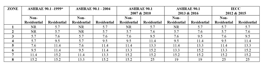
Table 2: Prescriptive R (minimum) Requirements for Mass Walls, Above Grade
ASHRAE Standard 90.1 Energy Standard for Buildings Except Low-Rise Residential Buildings. American Society of Heating, Refrigerating, and Air-Conditioning Engineers, Inc., Atlanta, GA.
* Prescriptive R requirements are approximate for illustration purposes only. ASHRAE 90.1-1999 had 26 climate zones. In 2004 and thereafter the number of zones were reduced to 8. Since there is not a direct conversion from 1999 to 2004, the 1999 columns are an approximation based roughly on the boundaries as defined by CDD50 and HDD65 for each region.

Figure 1: United States Climate Zone Map (Figure B1-1, ASHRAE Standard 90.1-2013)
What is the Driver for the Rise of CI?
The first version of what was to become ASHRAE 90.1 was published in 1975. Since then it has been updated many times due to rapid changes in building technology and energy prices. Tables 1 and 2 chart the increase in prescriptive R-value recommendations across several editions of energy design standards.
ASHRAE 90.1 first introduced a prescriptive recommendation for CI in 1999. The immediately preceding edition in 1989 had no specific reference regarding the use of CI. Beginning in 1999, the prescriptive recommendation for CI has moved further south, eventually reaching all the way to Climate Zone 1, while CI R-value recommendations for the other zones have steadily risen.
Drivers for CI Prescriptive R-Values; The 2030 Challenge
The evolution of CI in building walls from “non-existent” to “common practice” is the outcome of both common sense economics, and, attempts to reduce the impact of energy consumed by buildings on global climate change.
At the time that ASHRAE Standard 90.1-1999 was published there was little discussion about the relationship of buildings to the climate issue. In the early 2000’s, in a prominent national discussion lead by the influential environmental architect Edward Mazria, it was identified that buildings were responsible for about 50 percent of all the energy consumption and CO2 emitted in the United States.
In response Mazria conceived and introduced the “2030 Challenge,” an initiative that proposed that the architecture and construction communities adopt a series of greenhouse gas reduction targets for new and renovated buildings.
The targets set by the 2030 Challenge were:
- All new buildings, developments and major renovations shall be designed to meet a fossil fuel, greenhouse gas (GHG) emitting, energy consumption performance standard of 50 percent of the regional (or country) average for that building type.
- At a minimum, an amount of existing building area equal to that of new construction be renovated annually to meet a fossil fuel GHG emitting, energy consumption performance standard of 50 percent of the regional (or country) average for that building type.
- The fossil fuel reduction standard for all new buildings shall be increased to:
- 60 percent in 2010
- 70 percent in 2015
- 80 percent in 2020
- 90 percent in 2025
- And, be carbon neutral by 2030 (meaning zero fossil fuel, and GHG emitting energy to operate).
Shortly after the concept was introduced it was adopted by the American Institute of Architects, and others, including state and local governments. The U.S. Conference of Mayors soon followed. In April 2007 the ASHRAE Board of Directors adopted the challenge and soon signed a memorandum of understanding (MOU) with the U.S. Department of Energy (DOE) to establish the following energy reduction targets for subsequent editions of ASHRAE Standard 90.1:
- 90.1-2010, targeted 30 percent reduction in energy cost relative to the 2004 standard.
- 90.1-2013, targeted 50 percent reduction in energy cost relative to the 2004 standard.
Of course there were many building components and mechanical systems that ultimately contributed to the overall energy reduction goals, but, CI played a role as illustrated by the increasing R-values for CI in Tables 1 and 2 during this time period (See Tables 1 and 2 on the next page).
Optimum Insulation
The other important driver for CI becoming more mainstream as a building practice was economics and the concept of “optimum insulation.”
Although it requires an initial increased investment during construction, insulation creates reduced energy costs for the life of the building. The question then becomes, “how much insulation is enough?” “What is the optimum amount of insulation?”
“Optimum insulation” is the amount of insulation that has the lowest life cycle cost (LCC). LCC is expressed as:
LCC = FC+M+R+E – RV
LCC = Life Cycle Cost ($)
FC = First Cost ($)
M = Maintenance and repair cost ($)
R = Replacement Cost ($)
E = Energy Cost ($)
RV = Resale value or salvage ($)
The concept of determining the lowest life cycle cost (LCC) is illustrated in Figure 2.
Figure 2: Life Cycle Cost Analysis
In addition to adhering to the public policy principles of the 2030 Challenge and the MOU with DOE, the ASHRAE 90.1 standard committee also justifies insulation levels using sound economic principles.
Figure 2 illustrates the concept showing first cost for insulation/construction increasing as R-value increases. The principle is obvious, as one installs more insulation, the first cost of insulation increases. Equally obvious it captures energy cost and consumption decreasing as R-value increases.
The LCC is the lowest sum of “first cost” and “energy cost” at a given level of R-value. In this hypothetical example, R-20 is the lowest LCC, and, is therefore the “optimum insulation” level. Figure 2 only demonstrates the concept of “optimum insulation.”
Actual optimum levels must be calculated for specific climates, specific building construction types, specific building usage patterns and specific economic assumptions regarding construction and energy costs. The concept of Life Cycle Cost Analysis and Optimum Insulation are utilized by ASHRAE in the development of Standard 90.1 however it is a minimum standard that sometimes lags behind the upward trend of energy and construction costs, particularly when a building built today will have a useful life several decades into the future. Therefore, the path to raising awareness and increasing energy standards to include the use of CI was aligned with economic and public policy through the early 2000’s.
Performance Benefits Resulting From the Use of CI
The location of continuous insulation is determined by the type of construction, climate zone, building function and ease of construction. CI may be integrated as part of many common wall designs including steel framed and masonry cavity walls, rainscreens and rain barriers, pre-cast and tilt-up concrete panels. It can also be incorporated behind many types of cladding including architectural metal, masonry, stucco and EIFS. Generally, it is easiest to construct continuous insulation on the outboard side of the wall framing to minimize complex detailing around floor lines, exterior penetrations and openings.
When located on the outboard side of the wall, CI achieves two things: 1) it keeps the wall framing warmer, meaning it is closer to the building’s interior temperature, and, 2) the added CI R-value shifts the dew point, to the point that it often is located outside of the framing cavity insulation. Minimizing condensation inside walls reduces the likelihood of moisture accumulation which decreases the possibility of structural corrosion and decay and the opportunity for mold and mildew to develop.
Unfortunately, structural components (concrete masonry units, steel studs, wood studs and concrete) are better conductors than insulators. This results in thermal bridging or thermal short circuits where structural (and other) components penetrate the through the wall to the exterior.
Prior to the wide spread adoption of CI conventional construction practices, insulation was commonly installed between studs, in the stud cavity, in an exterior wall. Thermal imaging shown in Figure 3 shows increased heat flow where uninsulated steel stud framing meets the exterior sheathing and other uninsulated details along the roof line, while Figure 4 shows a building known to have CI over its steel framing and showing greatly reduced thermal bridging in the wall system compared to Figure 3.
Figure 3: Thermal Imaging of a Building with Cavity Insulation, but No CI
Figure 4: Thermal Imaging of a Building with Cavity Insulation, And CI
Thermal bridging reduces the effective R-value of the wall assembly by a percentage of area where stud framing is not separated from the exterior by CI. When CI is provided over the stud framing the effective R-value of the wall is improved.
By minimizing thermal bridging CI can make the enclosure wall more energy efficient and less likely to experience detrimental condensation related problems.
CI also helps manage the potential for moisture accumulation via the diffusion of water vapor through the wall at the molecular level. However, if a high quality air barrier is not present in the wall design, it is very likely that more moisture related problems may occur due to the leakage of moisture laden air than will occur from molecular diffusion. For effective enclosure wall system performance, both CI and water resistive air barriers must be carefully chosen and installed based on the demands of the climate zone, the use of the building, and the type of wall system construction.
Changes in Building Codes Because of the Use of CI
Perhaps the most prominent change in building codes resulting from the increased use of CI is a reawakening of NFPA 285.
NFPA 285 is a fire test standard that measures the likelihood that a wall system containing combustible components may be ignited by a fire plume emitting from a window opening, and then propagate the fire away from the point of origin either on the surface of the wall or through its core and cavities. Although it was never intended to be a test exclusively for EIFS, NFPA was largely viewed as a test for EIFS, and was not often utilized to evaluate other types of cladding or construction.
The wide spread adoption of the IBC and the rise of CI in energy standards happened to coincide in the early 2000’s. During this time, it was more common for walls that are required by the IBC to be made of noncombustible components. Walls were also required by the energy standard to be wrapped in CI, which is often, not always, a combustible foam plastic. In other words, new buildings were often required to be non-combustible construction, yet also required to be wrapped in combustible CI materials.
NFPA 285 is often required when combustible air/water barriers are used or when foam plastic insulation is used in the exterior walls of construction types I, II, III or IV. These construction types, by code definition, have exterior walls constructed of non-combustible materials.
The test standard NFPA 285 is referenced in many sections of the IBC including 1403.5 for water resistive barriers, and Section 2603.5.5 for foam plastic insulation. The now defunct ICBO Uniform Building Code first included the concept in the 1988 edition, requiring testing in accordance with the UBC Standard 17-6, a predecessor of NFPA 285. The other two national model building codes of that era also required full scale testing for exterior walls. The 1982 SBCCI Standard, and the 1984 BOCA National (Basic) Building Codes stated in their foam plastics chapters:
“Results of diversified or full scale fire tests reflecting an end use condition shall be submitted to the building official demonstrating that the (wall) assembly in its final form does not show any tendency to propagate flame over the surface or through the core when exposed on the exterior face to a fire source.” The intent was that a predecessor of NFPA 285 be utilized, the “Full Scale Multi-Story Test,” as it was called at the time.
It wasn’t until the rise of CI in the late 2000’s that NFPA 285 became a widely enforced test requirement. That is why many architects in the 2008-2010 time frame were caught unaware that their new designs including CI needed to be NFPA 285 compliant.
The NFPA 285 Test
The 30 minute test is conducted on a full scale 2-story wall assembly, built as it would be in the field, on the front side of a three sided test structure (See Figures 5 and 6). The test wall has a window in the center of the lower floor (See Figure 7). The test scenario is that a flashover fire, unrelated to the combustibles in the wall, has occurred in the lower story room emitting a fire plume through the window and out of the room of origin. Early in the 30 minute exposure the fire plume wraps around the window head, extending up the exterior surface of the wall (See Figure 8). To pass, the wall assembly must limit fire spread vertically and horizontally away from the window. The extent of fire spread is determined visually, measured in feet, and by temperature that is measured by thermocouples placed throughout the wall assembly (See Figure 9).
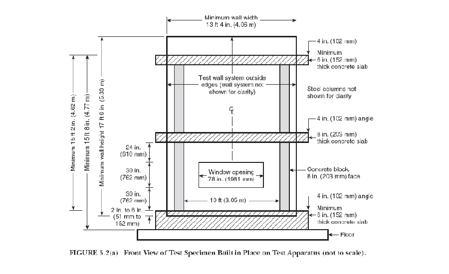
Figure 5: NFPA 285 Test Apparatus, Front Elevation

Figure 6: NFPA 285 Test Apparatus, Side Section
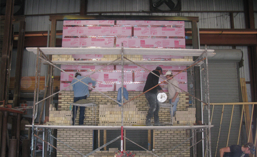
Figure 7: NFPA 285 Test Wall Under Construction

Figure 8: Fire Plume Exiting 1st Story Window

Figure 9: Wall Showing Limited Fire Spread After Brick Veneer Has Been Stripped
Selecting Continuous Insulation
When selecting the appropriate type of continuous insulation for exterior walls, there are some key characteristics that must be considered. The primary considerations are what type of cladding is specified and how much water is expected to penetrate the cladding? The type of cladding determines the degree of fire protection and UV protection that it will be capable of providing to the cavity and/or insulation and water/air resistive barrier in the cavity. The amount of water expected to penetrate the cladding will help determine the type of insulation that will perform effectively given the expected conditions inside the wall.
Types of Cladding
There are many types of cladding used on walls requiring NFPA 285 compliance. Common cladding materials include masonry veneers (brick, CMU, and stone both natural and manufactured), precast concrete and insulated precast concrete, terra-cotta, composites, laminates, architectural metal panels (both single skin and aluminum composite material (ACM), or metal composite materials (MCM). Masonry and concrete are themselves highly fire resistant and provide quite substantial protection for the potentially combustible layers of CI and/or the air/water resistive barrier inside the wall system. Other materials such as ACM’s provide very little fire resistance, and may themselves contribute to fire spread and require NFPA 285 testing even when used alone with no other combustibles in the wall system.
Rainscreen vs. Rain Barrier
Another important difference in cladding systems is the presence of open or closed joints. Rainscreen cladding, such as open joint panel systems or closed joint masonry veneer, are intended to allow water in and then direct it out through designed drainage paths. Rain barrier systems such as stucco or closed joint metal panel systems are designed with no joints or closed joints and are intended to repel water on the surface of the cladding.
This distinction in cladding systems is key to selecting the proper CI. Open joints allow ultra-violet (UV) light into the system, therefore the CI chosen must be UV-resistant or it must be covered to screen it from the daily UV exposure coming through the joints. Also, open joints allow fire penetration during the NFPA 285 test, therefore the CI selected must be more resistant to direct flame impingement.
Types of Continuous Insulation
CI is selected based on the cladding characteristics to determine the level of exposure to UV, water and fire. In addition CI must be chosen based on the required R-value needed, the space available in the wall to achieve it, and the permeance rating needed in the CI layer. With multiple performance characteristics, the choice of CI often comes down to an assessment of “must have” and “nice to have.” The following is an overview of three different CI solutions:
Extruded Polystyrene (XPS)
XPS is a rigid board, foam plastic insulation. It is “closed cell” meaning that cells are regular in size and independent (not interconnected) (See Figure 10). The polystyrene molecule is “hydrophobic” meaning that it has no affinity to bond with water. These two characteristics are unique to XPS making it the best choice for water resistance among all possible CI materials.

Figure 10: Extruded Polystyrene Cell Structure
XPS derives its R-value from the low-conductivity gas held captive in its cells for the life of the product. It has a long-term R-value of 5-per-inch of thickness when measured at a 75 degrees Fahrenheit mean temperature. As mean temperature decreases into a more wintery range of 40 degrees F, the R-value increases to 5.5-per-inch.
Water is highly conductive, therefore water absorbed in insulation will reduce its thermal effectiveness. Because XPS is highly water resistant, it maintains its R-value in the presence of any water in the cavity of the wall making it an excellent CI choice for closed joint, rainscreen, cavity wall drainage style systems.
XPS is a foam plastic which is combustible. It is also UV-sensitive resulting in the surface slowly becoming brittle with slow erosion after long-term exposure to sunlight through open cladding joints. Therefore XPS is not a good choice for use behind open joint cladding systems where the open joint will allow sunlight to penetrate on a daily basis, and allow fire and heat to penetrate in the event of an NFPA 285 type of event. XPS is commonly used behind all types of closed joint masonry veneer and precast concrete cladding systems. It is not used behind open joint systems like laminates and terra-cotta, and metal panel cladding systems.
Mineral Wool (MW)
MW used as CI is a semi-rigid board of bonded rock fibers. Its R-value of 4.2-per-inch of thickness when measured at a 75 degrees F mean temperature. The MW fiber does not absorb or bond with water. However, water may temporarily enter the voids in the fiber matrix and displace air, and then drain out as it experiences wetting and drying cycles when placed in a wet cavity wall condition.
MW retains its semi-rigidity and strength through wetting and drying cycles making it suitable for use in wet cavity wall situations when there is adequate space to achieve the necessary R-value. MW is non-combustible and highly fire resistant making it particularly well suited for use in any open joint systems that may be exposed to fire, and in non-masonry systems that provide little fire resistance such as behind ACM/MCM panels.
Due to the high degree of permeability and superior drainage capability, mortar damming is not a concern and the code prescribed 1-inch airspace is suitable. MW is also UV stable so it can tolerate long-term sunlight exposure through open joints. MW can be used behind virtually any type of cladding systems, and is particularly well suited for use where fire and UV exposure may come through open joints and where maximum R-value per-inch of thickness is not critical.
Polyisocyanurate (Iso)
Iso is a rigid board, foam plastic insulation. It is considered “closed cell.” However, cells are irregular in size and often interconnected (See Figure 11) allowing for the possibility of water intrusion.

Figure 11: Polyisocyanurate Cell Structure
The polyisocyanurate molecule is “hydrophillic” meaning that it has a molecular polarity opposite of water molecules. These two characteristics cause the water absorption level of Iso to be higher than XPS, its direct competitor in the foam plastic category.
All Iso is manufactured with a facer as a necessary part of the manufacturing process. Often it is the integrity of the facers that are relied upon to minimize exposure to water in wet cavity wall applications.
Iso derives its R-value from the low-conductivity gas held captive in its cells for the life of the product. Iso has a long-term R-value of 6 to 6.5-per-inch of thickness, depending on the manufacturer, when measured at a 75 degrees F mean temperature. As mean temperature decreases into a more wintery range of 40 degrees F, the R-value of some Iso products decreases to as low as 2 to 4-per-inch, again depending on the specific product and manufacturer.
The decrease in R-value-per-inch is a function of the captive low-conductivity gas in the cells of Iso, and its higher condensation temperature than the gas used to produce XPS. Iso loses its ability to insulate as the gas condenses to liquid inside the cells. As the mean temperature increases, the gas in the cells return to their gaseous state and R-value is recovered until the next dip into cold temperatures.
Some Iso products have an “engineered core” that yields higher fire resistance than that of generic Iso. The fire enhanced Iso products, although they are a foam plastic and are combustible, can be used behind cladding system that provide little to no fire resistance. That makes the “fire enhanced” Iso products suitable for use in open joint systems like terra cotta or precast concrete, and behind ACM/MCM composite metal panel systems. Check with the manufacturer for specific product details to ensure that the product specified has been verified to be NFPA 285 compliant behind the chosen cladding.
CI Construction Details
There are many options available when installing CI, including screws, air/water sealing washers, clips, z-girts and impaling pins. To the extent possible, careful attention should be given to minimizing thermal bridging through the CI layer to avoid negating the performance benefits of continuous insulation. Manufacturers are working on design guides to provide the highest performing, cost-effective and constructible fastening systems. Contact the manufacturers of CI products for the most current recommendations.
Integrating CI into the exterior wall involves changes in standard detailing. Not only will common wall sections be revised by simply including CI where it once was not included, but designers must also address changes in wall thickness and transitions. Other components in the wall such as the air/water barrier layer, and vapor control layer must also be adjusted to accommodate presence of CI and its influence on wall performance. Common details that may require new attention include:
- Transitions from foundation insulation to wall insulation
- Masonry ledge thickness
- Window and door opening thickness
- Sill pan, head, and jamb detailing (to seal against potential fire intrusion in an NFPA 285 event)
- Floor line and detailing
- Steel ledge, shelf angle and detailing
- Transitions from wall to roof
The choice of the cladding, insulation and the details around openings, are critical in accomplishing an assembly that is NFPA 285 compliant. With CI and NFPA 285 now a “standard method and material” practice, scores of assemblies have been tested or have been accepted through engineering judgments. Check with system manufacturers for design guide for the various product options discussed herein.
Conclusion
Continuous insulation is no longer viewed as appropriate for only the most efficient buildings or a best practice. It is now customary and main stream. As described in this course, multiple advances in research and analysis have proven the benefits of CI to the point that it has been integrated as a standard practice in codes and standards and projects throughout the country. Designers must identify the type of cladding for a building design, and then evaluate the demands that it will place on the selection of a type of continuous insulation product.
Considerations include water resistance, air leakage resistance, appropriate fasteners and assembly fire testing. Designers must review standard details to ensure they are aligned with continuous insulation design principles that are quickly becoming standard practice. As a result of this new best practice, energy consumption, moisture accumulation, and the growth of mold and mildew are all anticipated to be reduced in future buildings throughout America.
Herbert Slone is a registered architect and senior manager of Commercial Building Systems for Owens Corning. He has over 41 years of experience in construction.

|
Owens Corning develops, manufactures and markets insulation, roofing, and fiberglass composites. Global in scope and human in scale, the company’s market-leading businesses use their deep expertise in materials, manufacturing and building science to develop products and systems that save energy and improve comfort in commercial and residential buildings. Through its glass reinforcements business, the company makes thousands of products lighter, stronger and more durable. Ultimately, Owens Corning people and products make the world a better place. Based in Toledo, Ohio, Owens Corning posted 2015 sales of $5.4 billion and employs about 16,000 people in 25 countries. It has been a Fortune 500® company for 61 consecutive years.
Explore and interact with key industry products through our exclusive Interactive Product Spotlight on Owens Corning Enclosure Solutions.
http://www.owenscorning.com.
|


