This CE Center article is no longer eligible for receiving credits.
It should also be noted that the ASTM E119 exemption scenario was evaluated years before the development of the ASTM E2307 test method. The Loss Prevention Council in the United Kingdom conducted testing with fire exposure similar to ASTM E119, with fire impingement on the inboard side of the curtain wall. It was recognized early on that if left unprotected, the void created between the floor slab and exterior wall would allow fire and smoke to propagate to the floor above. It was thought that simply filling that void with mineral wool would be an easy fix. However, if you do so without protecting a portion of the spandrel area, the glass curtain wall will fail and the mineral wool will fall out of the void.
The cross-section drawing in Figure 1 illustrates the test set up by the Loss Prevention Council in which mineral wool was installed between the glass and face of the floor slab. Within the first 10 minutes of the fire, the glass broke out and the safing fell out of the void, allowing fire to propagate to the next floor.
As this test illustrates, if the ASTM E119 exception is followed in this case, once the glass breaks, the safing is gone. At best, the ASTM E119 exception will afford only 10 to 15 minutes of protection.
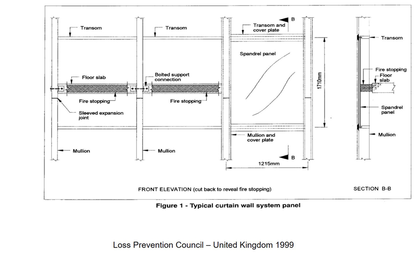
Figure 1: A test conducted in 1999 by the Loss Prevention Council in the United Kingdom installed mineral wool between the glass and face of the floor slab.
It should also be noted that today there are zero-spandrel and all-vision glass curtain wall designs available that have been tested to ASTM E2307. These solutions can be found in the Intertek Fire-Resistance Directory. Specifying assemblies tested to ASTM E2307 rather than utilizing the ASTM E119 exception will elevate the level of fire safety for the building occupants and should be the minimum requirement when designing and installing short or zero-spandrel curtain wall facades. The ASTM E119 exception should never be used in lieu of an ASTM E2307 tested and listed system.
Misconception #3: Steel back pans provide the safest, most robust PFC systems.
Back pans are galvanized steel sheets that are mechanically attached and sealed to the curtain wall framing around the perimeter behind opaque areas of a curtain wall. In these systems, the steel back pan serves as the vapor barrier. The use of steel back pans in PFC systems is becoming quite common because of the popularity of unitized systems; however, these systems must be properly protected. Even though steel does not melt, when exposed to elevated temperatures, the steel pan will buckle and warp due to its high expansion coefficient. When this occurs, the safing insulation cannot maintain its compression or follow the warping or deflection of the back pan. Small seams may form at safing line, allowing flame and hot gases to propagate the next floor.
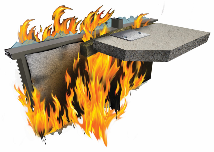
This depiction shows how improperly installed steel back pan assemblies perform when exposed to the fire conditions of ASTM E2307. Note the deflection of the interior back pan that allows flame and hot gases to propagate through the safe-off joint.
There are specific UL/Intertek listed systems that address the protection of these types of assemblies; however, it should be noted that these configurations are the most difficult to pass when testing to ASTM E2307.
There are a variety of systems that utilize interior steel back pans. One feature these solutions have in common is a high frequency of attachment for both the back pan and the mineral wool curtain wall insulation. Some older systems required covering the interior face of back pan with mineral wool, while next-generation systems incorporated a safing shelf to protect the safing line from fire propagation through the peaks and valleys that are created when the back pan warps. Most systems require backer reinforcement at the slab edge.
Newer systems have eliminated the need for covering the interior back pan. These systems eliminate the need for a backer bar by utilizing the location of the horizontal windowsill transom plus the return lip of the back pan for reinforcement. However, it should be noted that mineral wool—specifically Intertek or UL approved mineral wool—must be used in these back pans to show that they meet ASTM E2307 and the building codes. Not just any mineral wool insulation will do. Look for the UL or Intertek classification marking. Because these systems are more prone to failure, you must also follow all of the design criteria of the listed system.
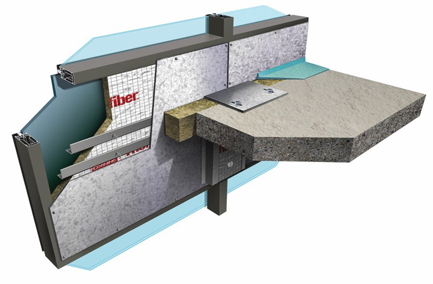
This system offers a 2-hour F rating for interior back pan protection. Note the reinforcement at the safe-off line. These design details are needed to keep the back pan from warping when exposed to fire.
Misconception #4: Vertical mullion protection is not necessary.
In 98 percent of all UL/Intertek tested and listed aluminum-framed curtain wall systems, vertical mullions within the spandrel area must be protected with UL/Intertek approved mineral wool mullion cover insulation. Aluminum will melt as early as 9 minutes into a fire. And yet, these aluminum framing members are critical for keeping the system together for the required hourly rating of the system. Typically, mineral wool spandrel insulation is mechanically attached to the mullions. If the aluminum framing is left exposed, it will melt and cause the mineral wool spandrel insulation to fall out or dislodge, which in turn can cause the mineral wool safing at the interior joint to become compromised and result in an early failure in the system.
Shown here is mullion exposure to fire during testing. Note that the exposed side of the vertical mullion is almost completely melted out.
Note the complete loss of horizontal transom and vertical mullions after exposure during an ASTM E2307 fire test.
There are a few systems available where mullion covers are not required; however, these systems include unique design features that ensure all materials stay intact during a fire.
You cannot assume that just because a very few systems do not require mullion covers that they are not necessary. In fact, mullion covers should be utilized in 98 percent of all curtain wall assemblies as an added safety layer. In addition to protecting the mullions from high temperatures during a fire, mullion covers are often also required for moisture and thermal protection.
Misconception #5: Fire performance of exterior facade composite panels does not need to be considered in PFC design.
We are starting to see exterior facade panels other than glass on high-rise structures. Increasingly, curtain wall designs include untested exterior facade panels, such as metal composite panels (MCMs), aluminum composite panels (ACMs), and high pressure laminates (HPLs), among others. These combustible panels can add to the fuel load of a curtain wall under fire conditions. When the fire performance as per ASTM E2307 is unknown, exterior facade panels should be evaluated using NFPA 285: Standard Fire Test Method for Evaluation of Fire Propagation Characteristics of Exterior Non-Load-Bearing Wall Assemblies Containing Combustible Components. The purpose of the NFPA 285 test is to determine that combustibles, when exposed to fire on the exterior face of the wall, do not allow for fire to spread a specified distance over the surface or through the core of the otherwise noncombustible wall assembly.
It should be noted that although NFPA 285 uses the same ISMA two-story simulation of a fire exposure as does ASTM E2307, the test duration and pass/fail criteria are completely different. In other words, just because a system has passed NFPA 285 does not mean it meets the requirements of E2307, and vice versa.
In addition, the exterior panels should be attached independently from the PFC system. Combustible and untested panels should never provide structural support for the perimeter fire-barrier system.
Conclusion
PFC is vital for ensuring the life safety of building occupants. These systems work by compartmentalizing a fire to the room of origin long enough for occupants to exit the building; however, they must be correctly designed and installed to be effective. Successful PFC systems include six critical design criteria and are tested to ASTM E2307. However, there are some common misconceptions about these systems, especially as all-vision glass and unitized systems with steel back pans become more popular. By understanding these misconceptions, specifiers can avoid choosing inferior solutions and ensure that they are specifying the safest, most effective systems for their buildings.
Juliet Grable is an independent writer and editor focused on building science, resilient design, and environmental sustainability. She contributes to continuing education courses and publications through Confluence Communications. www.confluencec.com
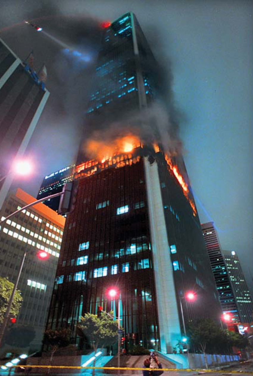
In 2005, a fire broke out on the 21st floor of The Windsor, an iconic high-rise building located in Madrid, Spain. The fire spread quickly from floor to floor. After burning for 20 hours, the floor spans of the upper stories collapsed.
There are few visions as terrifying as a skyscraper with multiple floors ablaze. High-rise buildings present a special problem when it comes to protecting occupants from the risk of fire. Large numbers of occupants must travel long vertical distances to exit the building using limited points of egress. Despite these challenges, building codes and design practices have greatly improved the safety of these buildings over the years.

All images courtesy of Owens Corning
Steinway Tower, a 1,400-foot, 82-floor residential high-rise in New York City, has the distinction of being the world’s skinniest skyscraper. Completed in 2018, the project incorporated enhanced fire protection in curtain wall and perimeter fire-containment (PFC)systems.
There are three major strategies when it comes to protecting the life safety of building occupants: detection, suppression, and compartmentation. Detection consists of alarm systems such as smoke and heat detectors. Suppression includes active systems that rely on switched mechanisms to function—for example, a sprinkler system that is triggered by rising temperatures. Compartmentation, also known as passive fire protection, is a strategy that divides a building into compartments through the use of fire-rated walls and floors and keeps a fire contained at the source of origin.
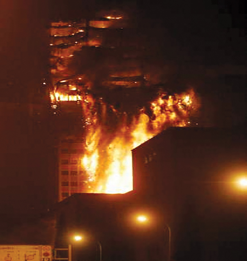
This photo of the Windsor Tower located in Madrid, Spain shows the results of “leapfrog” fire propagation. Note how the fire has spread vertically along the outside of the high-rise.
A passive system prevents or slows the spread of fire from the room of origin to other building spaces, limiting building damage and providing more time for the building occupants to safely evacuate or reach an area of refuge. Compartmentation also allows first responders to effectively fight the fire. Passive systems do not require on/off mechanisms; once properly installed, they provide protection continuously.
Detection systems and active strategies may be tampered with or purposely disarmed. Both of these strategies are also subject to electrical and mechanical failures, and therefore may not always function properly. For the best protection, buildings will utilize all three strategies; this way, if one fails, there is a backup system in place to increase escape time and occupant safety.
The size and number of buildings being constructed today are bigger in every dimension, and they contain more occupants than ever before. Consequently, high-rise fire protection has never been more critical. Curtain wall systems are becoming increasingly common in these buildings. These nonstructural exterior building coverings typically consist of exterior cladding made from lightweight, durable materials, such as aluminum panels, thin stone panels, or glass infill in a combination of spandrels and vision glass.
Although curtain wall systems enable distinctive and dynamic designs while protecting buildings against the elements, they have a unique feature that makes them vulnerable to spreading fire from floor to floor.
Upon installation, curtain wall systems create a void between the fire-rated floor slab and the edge of the nonrated curtain wall. In the event of a fire, this unprotected space at the edge of the slab acts as a chimney for fire and hot gases, helping a fire to rapidly spread from floor to floor. Though it may seem like a small space—theses joints are often just a few inches wide—when multiplied by the number of lineal feet on all four sides of the building and by the number of stories in the building, this space becomes a significant pathway for smoke and hot gases.
This is exactly what happened in the case of The Windsor. This high-rise was built at a time when building codes did not require the perimeter void to be protected. Consequently, fire was able to rapidly propagate from floor to floor.
Perimeter fire-containment (PFC) systems mitigate this risk by providing firestopping at the void between the slab edge and the curtain wall. PFC systems must be designed and properly installed to mitigate the risk of fire. Such systems are tested by independent third-party labs and listed in their directories.
PFC systems can mean the difference between life and death, and a building that does not have an appropriately designed and properly installed system is a serious fire risk. They are especially important in tall structures, where the points of egress are limited and escape time becomes critical. Fire attack strategies are also limited in tall buildings. Fire services ladder trucks can only reach so high; anything above the seventh floor is out of the realm of a feasible ground attack.
Applicable Codes and ASTM Tests for PFC Systems
To understand common misconceptions about PFC systems, it is essential to first understand the code requirements and testing standards that are relevant to these systems.
Fire investigative reports have consistently shown that unprotected or improperly protected penetrations and joints have caused millions of dollars in property damage and contributed to the loss of life and injuries due to the uncontrolled migration of fire, smoke, and toxic gases. Consequently, the International Code Council (ICC), International Building Code (IBC), and most state and local codes clearly state the requirements for passive fire protection. The IBC includes fire testing and performance requirements for firestopping for penetrations and joints. These provisions can be found in Chapter 7: Fire and Smoke Protection.
Relevant Building Codes
Section 715.4: Exterior Curtain Wall/Floor Intersection of IBC 2018 states that, where fire-resistance-rated floor or floor/ceiling assemblies are required, voids created at the intersection of the exterior curtain wall assemblies and such floor assemblies shall be sealed with an approved system to prevent the interior spread of fire. Such systems shall be securely installed and tested in accordance with ASTM E2307 to provide an F rating for a time period not less than the fire-resistance rating of the floor assembly.
Although local codes may vary, fire-resistance-rated floor/ceiling assemblies are generally required in construction types I-A, I-B, II-A, III-A, and V-A. It is important to note that even when the floor/ceiling assembly is not required to be fire-resistance rated, Section 715.4.1 still requires that the joint be sealed with an approved material or system—typically mineral wool safing insulation—to prevent or slow the interior spread of fire and hot gases between stories.
This section of code does contain an exception for situations where vision glass extends all the way to the finished floor level. In these cases, code allows the void created at the intersection of the exterior curtain wall and floor assembly to be sealed with an approved material to prevent the interior spread of fire. This material “must be securely installed and capable of preventing the passage of flame and hot gases sufficient to ignite cotton waste,” as tested by ASTM E119. The material must resist the fire for a time period that is equal to or greater than the fire-resistance rating of the floor assembly. We will discuss the “ASTM E119 exception” more thoroughly later in this course; however, it is important to note that taking advantage of this exception is not recommended.
First, although ASTM E119 is an important test for evaluating building elements, it only tests fire exposure on one side of the assembly. Second, at the time the exception was incorporated into this section of code, there existed no designs tested to ASTM E2307 that allowed for the extension of vision glass down to the floor line. This is no longer true.
To summarize, Section 715.4 sets forth the two principles that form the basis of effective PFC systems and the criteria by which any non-tested and listed system shall be judged: that the void between the curtain wall and floor slab is properly sealed with a system tested to ASTM E2307, and that the firestopping system achieves a fire rating at least as high as the rated floor. Now we will take a look at the test standards used to evaluate PFC systems.
ASTM Test Standards
Section 715.4 of the 2015 IBC requires that only approved PFC systems be used. Such systems are specifically designed and constructed to protect the perimeter of an aluminum-framed curtain wall in accordance with ASTM E2307 and the IBC. However, the IBC recognizes that every building differs in its design details, and so engineering judgments may be required to help the project team adjust the design to ensure that the containment system will function as needed for the specific site.
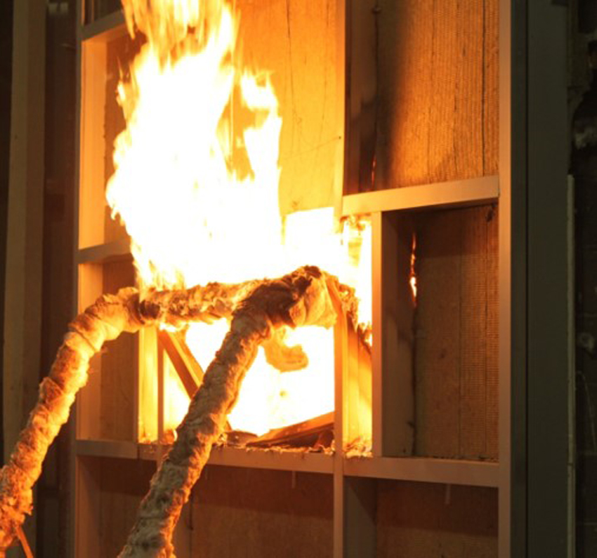
ASTM E2307: Standard Test Method for Determining Fire Resistance of Perimeter Fire Barriers Using Intermediate-Scale, Multistory Test Apparatus (ISMA) is the standard designed to test and measure how well a perimeter fire-barrier system can maintain a seal and prevent interior fire from spreading, as the exterior wall assembly deflects and deforms when exposed to fire. The goal is to determine how long the perimeter fire barrier will prevent the flame from penetrating through the opening between the wall assembly and the floor assembly.
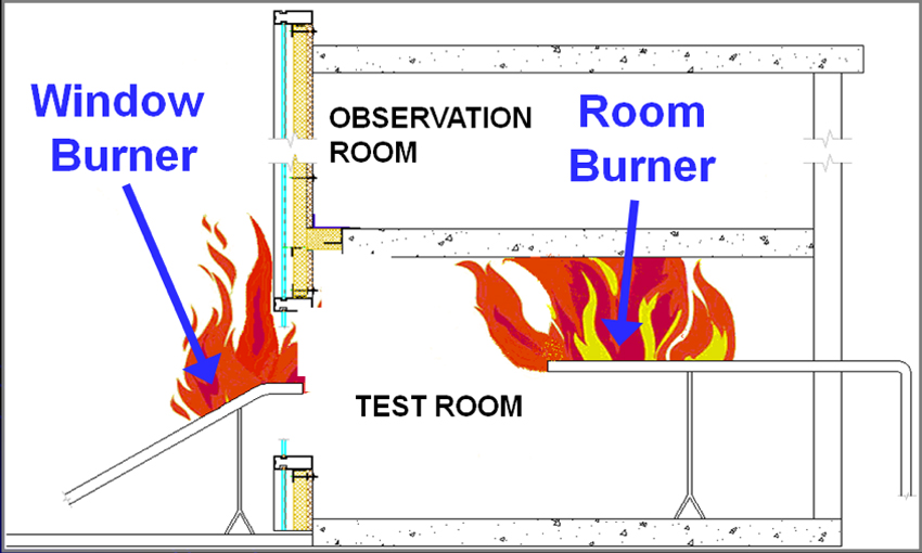
The ISMA structure is a two-story furnace that subjects a perimeter fire-barrier system to fire exposure from two sides at once. It is designed to simulate a building fire that originates on one floor and causes the windows to break, allowing the flames to escape the room of origin and impinge directly on the exterior of the curtain wall. The test focuses on the joint, which is protected by the PFC system. ASTM E2307 exposes the joint to fire from the room of origin and exposes the exterior wall to fire from both the interior and exterior as the fire plume exits the room through a window opening.
The fire originates on the first floor, or “burner room.” A second floor is located directly above the burner room and functions as the observation room. An interior burner is used to start a fire in the first floor room. Soon the room fills with flames and hot gasses. Approximately 5 minutes later, the exterior burner is ignited to simulate fire exposure on the outside of the building. When the vision glass on the first floor breaks, flames and hot gasses spread up the face of the exterior wall and through the joint between the floor slab and perimeter curtain wall. The objective is to prevent flames and hot gasses from entering into the room above. If the fire breaks through the upper-story windows during the test, the system will have failed to compartmentalize the fire.
Tested systems receive two ratings: The F rating is the resistance to fire spread, in hours. It is a measure of the number of hours the assembly resists the propagation of fire to the unexposed side through the interior joint.
The T rating is not a pass/fail criteria per E2307 but is simply reported in the listing. This rating is a measure of the time period, in hours, that the firestop system limits the maximum temperature rise to 325 degrees Fahrenheit (163 degrees Celsius) above its initial temperature on the non-fire side.
The UL testing laboratory provides an alternative rating called the Integrity rating. It includes the F rating, but it also evaluates the passage of flame through openings in the curtain wall above the PFC system.
Recall that “leapfrog” describes the condition where a fire breaks the glass in the room of origin, allowing flames and hot gasses to escape outside the building and up the face of the curtain wall. There, the fire breaks through and reenters the building by means of the vision glass in the floor above. Although not a requirement of the building codes, this is still a critical area that should be considered for maximum protection and compartmentation of a fire.
Shown is an illustration of the ISMA Test Apparatus. The test begins with ignition of first-floor interior burners. The objective is to keep fire from spreading through the interior joint between floor and exterior curtain wall on the second floor.
ASTM E2874: Standard Test Method for Determining the Fire-Test Response Characteristics of a Building Spandrel-Panel Assembly Due to External Spread of Fire. Although the path of fire via the exterior curtain wall is not currently addressed by the IBC codes, a new ASTM test standard was developed in 2019 to address this fire risk. Sometimes called the “Leapfrog Standard,” ASTM E2874 can be used as total fire-containment method when evaluating buildings that are a higher risk, such as health-care facilities, hospitals, and retirement dwellings, where egress out of a burning structure could be delayed.
As the name implies, ASTM E2874 evaluates the fire performance of an exterior wall assembly, principally the building perimeter spandrel system, for its ability to prevent the spread of fire to the interior of a room one adjacent storey above via fire spread from the exterior of a building. The test sample includes the exterior wall spandrel panel assembly, fasteners, structural supports, and any glazed openings. The test itself simulates a post flashover fire exposure within a compartment that is venting to the exterior of the building and spreading to the floor above via the building’s exterior. The testing apparatus is modelled after the one prescribed in ASTM E2307. As with ASTM E2307, assemblies receive an F rating and T rating.
Basic Criteria for the Design and Installation of PFC systems
Most curtain wall assemblies are designed around a tested and listed third-party PFC system. Though these systems vary when it comes to exterior spandrel panels, heights, and locations relative to the floor, most share six basic design components, which are critical to ensuring the system functions and contains fire to the room of origin, allowing occupants time to escape a burning structure.
Firestop system designs are tested and listed by independent testing agencies, such as UL and Intertek. It is important to note that, although third-party fire-resistance directories include hundreds of tested PFC systems, many architectural designs do not match these systems exactly. The design professional will almost always need to seek an engineering analysis or judgment to address any deviations in the designed system from a tested system.
An engineering judgment, or EJ, is an evaluation of the anticipated performance of a proposed firestop assembly that has not itself been fire tested. The evaluation is conducted by comparing the proposed system to listed and tested systems that is similar in nature. In any case, systems requiring EJs must still address the six critical criteria outlined below.
- Use Underwriters or Intertek Laboratories approved mineral wool insulation tested to ASTM E2307. Mineral wool insulation, at the required densities and thickness, is the only tested and proven material that will provide protection to both the curtain wall spandrel and the interior joint. Of the many insulation options available, mineral wool is best suited to the challenges of PFC, primarily because mineral wool has extremely high melting temperatures (upward of 2,000 degrees Fahrenheit). Mineral wool is the only insulation material that has been tested and proven to protect spandrel wall components. However, not just any mineral wool insulation will do, and it must be tested and approved in UL or Intertek designs as per ASTM E2307.
- Follow the required mechanical attachment method per the tested and listed ASTM E2307 compliant system for attaching the approved mineral wool insulation. During a fire, building components are subjected to turbulence, movement, and gravitational pull. Without mechanical fasteners, the insulation can become dislodged, allowing fire to propagate to the next floor. A range of fasteners may be used to attach mineral wool insulation to the curtain wall. However, the fasteners must be installed per the UL/Intertek listing’s installation requirements to make sure that the system functions as it was designed in the event of a fire.
- Provide backer reinforcement at the safe-off line per the UL/Intertek listed assembly. All systems require some type of reinforcement of the mineral wool insulation at the safe-off line. This prevents the spandrel insulation from bowing due to the compression force at the safing joint. Most listed systems reference either a 20-gauge steel T-bar, L-angle, or hat channel, but other systems may use different components to reinforce the curtain wall insulation.
The reinforcement also ensures a tight seal at the interior joint. If the joint is not sealed properly, the spandrel insulation will flex, creating gaps or seams where flames and gases may penetrate and potentially ignite combustibles on the floor above.
A common misconception is that metal panels such as aluminum or steel back pans will provide the necessary reinforcement. However, testing has proven these panels to be a failure point at the safing line if not properly reinforced, no matter what the material. We will discuss steel back pans in more depth later in this course.
Note that some listings do not require backer or reinforcement members; in these cases, the design has specialized components, such as the location of the window sill transom in combination with mechanical fasteners or additional mineral wool insulation to provide the support that is required to maintain compression at the safe-off void.
- Compression-fit UL/Intertek approved mineral wool safing insulation must be installed within the void between the floor assembly and the exterior curtain wall insulation per the tested and listed system. The mineral wool insulation must be of the correct density and compression to create a tight and proper seal at the interior joint, so that gases cannot pass through the joint. Safing can be installed with the fibers running either vertically or horizontally. However, designs are very specific about approved materials as well as fiber orientation, depth, density, and compression of the installed safing.
- Exposed vertical aluminum framing must be protected with UL/Intertek approved mineral wool insulation mullion covers. Because this detail is seen as contributing little to the performance of the assembly, mullion covers are often removed from the system, especially if they obstruct aesthetic elements, such as interior finishes or window shade pockets. However, these covers play a critical role. They protect both the aluminum framing and the mechanical fasteners that keep the spandrel insulation in place. The framing also helps keep the exterior wall in position so that the safing joint materials continue to block fire and smoke. Aluminum will melt at 1,220 degrees Fahrenheit, or as early as 9 minutes into a fire. If mullion covers are eliminated, the exterior wall may fail sooner, causing loss of compression of the joint safing material. The end result is a system that provides a much shorter window of protection than required.
- Smoke must be prevented from passing through the safe-off area per the approved tested and listed UL/Intertek assembly. Smoke inhalation is responsible for the majority of fire-related deaths. To prevent smoke from entering the safe-off area, smoke sealant must be applied on top of the safing insulation on the nonexposed side of the fire-containment system. This essentially creates a smoke barrier that compartmentalizes the smoke and keeps it from passing to another compartment. Specific UL or Intertek designs include approved smoke sealants. The smoke seal is commonly spray-applied to the top, or non-fire exposure side of the safing, forming a smoke barrier which contributes to the assembly’s L rating or leakage rating.
Five Common Misconceptions about PFC systems
Now that you understand the critical design criteria for design and installation of PFC systems, let’s look at common misconceptions about PFC. These misconceptions relate to common design and installation errors as well as recent trends in zero-spandrel or all-vision glass assemblies and the increasing popularity of unitized curtain walls with back pans. Both of these create a unique and challenging firestopping condition that must be addressed.
Misconception #1: Mineral wool is mineral wool; any type and manufacturer of mineral wool can be used in PFC systems.
A common misconception is that all types of mineral wool provide the same level of fire-resistive characteristics. As long as you have the correct density and thickness of mineral wool, the PFC system will perform and provide the required level of fire protection. However, this is not true.
There is more to the manufacturing of mineral wool than simply melting rocks. In fact, mineral wool manufacturers have patented technology around the equipment that transforms molten lava material (slag and natural occurring rock) into fiber, as well as proprietary formulations in rock/slag and binder chemistries that produce specific performance attributes. For example, some mineral wool products are designed purely for thermal and moisture performance, while other formulations enhance the material’s acoustical attributes and are ideal for applications where sound attenuation is key. Still other chemistries are developed for industrial applications such as insulating ovens and kilns.
Although all mineral wool products are made of raw materials that make them noncombustible, one cannot assume that a product designed for sound control will provide the level of fire protection needed for a structural column subjected to rigorous fire conditions.
Similarly, an industrial 4-inch-thick, 4-pcf-density mineral wool insulation will not provide the same level of fire protection as curtain wall or safing insulation in a UL/Intertek tested and classified PFC system. The components of a PFC system must be able to withstand direct flame impingement and temperatures greater than 1,800 degrees Fahrenheit while maintaining their structural integrity. This underscores the importance of specifying PFC systems that utilize mineral wool that has been tested, verified, and marked by the independent third-party laboratories specific to ASTM E 2307.
Misconception #2: The ASTM E119 exception, allowed in the IBC, can be used in lieu of a tested and listed system tested to ASTM E2307.
Some curtain wall manufacturers offer designs that feature either short spandrels or no spandrels at all (only vision glass). Until recently, these designs presented a special problem for firestopping. Section 715.4 of the IBC states that the void created between the rated floor assembly and nonrated exterior wall must be sealed with an approved system, tested to ASTM E2307, which remains securely in place for the time period equal to the fire-resistance rating of the floor assembly. As was mentioned earlier, an exception in this same code section addresses assemblies where vision glass extends to the finished floor level. This section allows the interior void to be sealed with an approved material tested to ASTM E119, which shows it is capable of staying in place and preventing fire to spread through the safe-off area.
At the time this exception was adopted into the code, there were no listed systems with either all vision glass or vision glass extending down to the floor level that had been tested to ASTM E2307. Today, there are.
Specifiers should always utilize a system that has been tested to ASTM E2307 since this test more closely represents the conditions of a real fire. Recall that ASTM E2307 exposes the assembly to fire on both sides at the same time for the 2- or 3-hour period of the fire test. In contrast, ASTM E119 exposes fire to only one side of the system and does not represent an expected fire scenario in a high-rise building.
Shown is the intermediate scale multistory test apparatus used in the ASTM E2307 fire-resistance test.
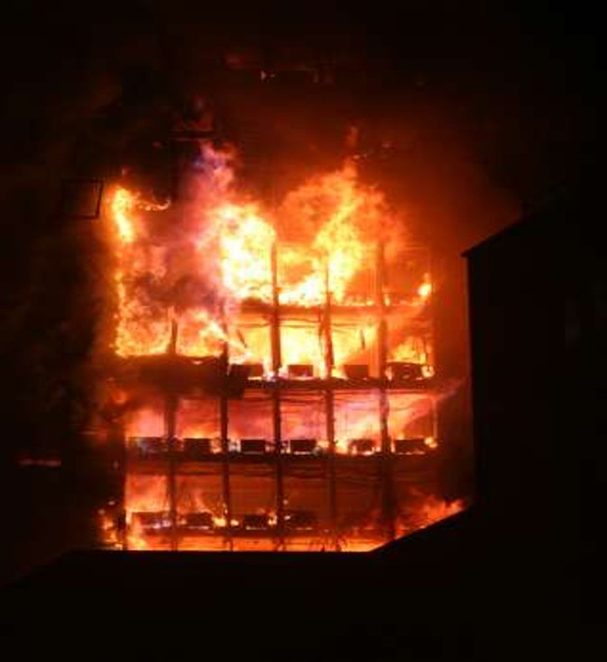
Notice the flame height attacking the exterior on The Windsor high-rise in Madrid, Spain, that was destroyed by fire in 2005.
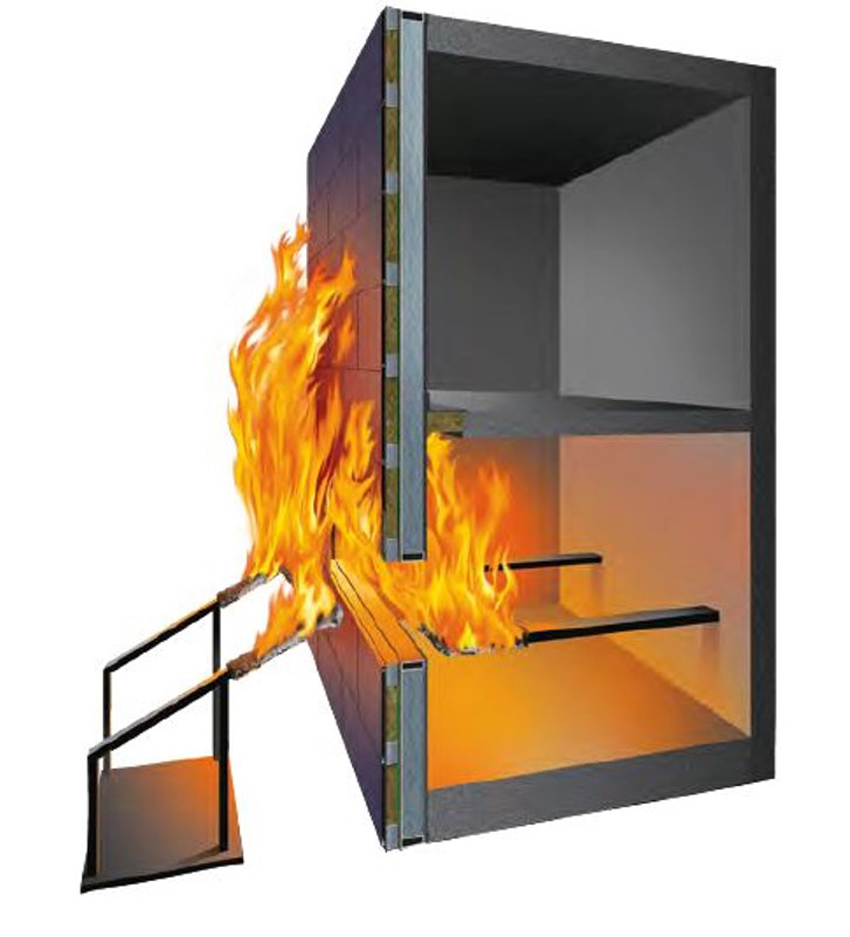
It should also be noted that the ASTM E119 exemption scenario was evaluated years before the development of the ASTM E2307 test method. The Loss Prevention Council in the United Kingdom conducted testing with fire exposure similar to ASTM E119, with fire impingement on the inboard side of the curtain wall. It was recognized early on that if left unprotected, the void created between the floor slab and exterior wall would allow fire and smoke to propagate to the floor above. It was thought that simply filling that void with mineral wool would be an easy fix. However, if you do so without protecting a portion of the spandrel area, the glass curtain wall will fail and the mineral wool will fall out of the void.
The cross-section drawing in Figure 1 illustrates the test set up by the Loss Prevention Council in which mineral wool was installed between the glass and face of the floor slab. Within the first 10 minutes of the fire, the glass broke out and the safing fell out of the void, allowing fire to propagate to the next floor.
As this test illustrates, if the ASTM E119 exception is followed in this case, once the glass breaks, the safing is gone. At best, the ASTM E119 exception will afford only 10 to 15 minutes of protection.
Figure 1: A test conducted in 1999 by the Loss Prevention Council in the United Kingdom installed mineral wool between the glass and face of the floor slab.
It should also be noted that today there are zero-spandrel and all-vision glass curtain wall designs available that have been tested to ASTM E2307. These solutions can be found in the Intertek Fire-Resistance Directory. Specifying assemblies tested to ASTM E2307 rather than utilizing the ASTM E119 exception will elevate the level of fire safety for the building occupants and should be the minimum requirement when designing and installing short or zero-spandrel curtain wall facades. The ASTM E119 exception should never be used in lieu of an ASTM E2307 tested and listed system.
Misconception #3: Steel back pans provide the safest, most robust PFC systems.
Back pans are galvanized steel sheets that are mechanically attached and sealed to the curtain wall framing around the perimeter behind opaque areas of a curtain wall. In these systems, the steel back pan serves as the vapor barrier. The use of steel back pans in PFC systems is becoming quite common because of the popularity of unitized systems; however, these systems must be properly protected. Even though steel does not melt, when exposed to elevated temperatures, the steel pan will buckle and warp due to its high expansion coefficient. When this occurs, the safing insulation cannot maintain its compression or follow the warping or deflection of the back pan. Small seams may form at safing line, allowing flame and hot gases to propagate the next floor.
This depiction shows how improperly installed steel back pan assemblies perform when exposed to the fire conditions of ASTM E2307. Note the deflection of the interior back pan that allows flame and hot gases to propagate through the safe-off joint.
There are specific UL/Intertek listed systems that address the protection of these types of assemblies; however, it should be noted that these configurations are the most difficult to pass when testing to ASTM E2307.
There are a variety of systems that utilize interior steel back pans. One feature these solutions have in common is a high frequency of attachment for both the back pan and the mineral wool curtain wall insulation. Some older systems required covering the interior face of back pan with mineral wool, while next-generation systems incorporated a safing shelf to protect the safing line from fire propagation through the peaks and valleys that are created when the back pan warps. Most systems require backer reinforcement at the slab edge.
Newer systems have eliminated the need for covering the interior back pan. These systems eliminate the need for a backer bar by utilizing the location of the horizontal windowsill transom plus the return lip of the back pan for reinforcement. However, it should be noted that mineral wool—specifically Intertek or UL approved mineral wool—must be used in these back pans to show that they meet ASTM E2307 and the building codes. Not just any mineral wool insulation will do. Look for the UL or Intertek classification marking. Because these systems are more prone to failure, you must also follow all of the design criteria of the listed system.
This system offers a 2-hour F rating for interior back pan protection. Note the reinforcement at the safe-off line. These design details are needed to keep the back pan from warping when exposed to fire.
Misconception #4: Vertical mullion protection is not necessary.
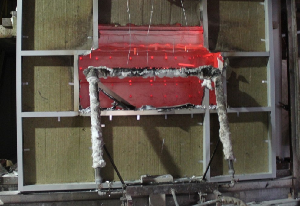
In 98 percent of all UL/Intertek tested and listed aluminum-framed curtain wall systems, vertical mullions within the spandrel area must be protected with UL/Intertek approved mineral wool mullion cover insulation. Aluminum will melt as early as 9 minutes into a fire. And yet, these aluminum framing members are critical for keeping the system together for the required hourly rating of the system. Typically, mineral wool spandrel insulation is mechanically attached to the mullions. If the aluminum framing is left exposed, it will melt and cause the mineral wool spandrel insulation to fall out or dislodge, which in turn can cause the mineral wool safing at the interior joint to become compromised and result in an early failure in the system.
Shown here is mullion exposure to fire during testing. Note that the exposed side of the vertical mullion is almost completely melted out.
Note the complete loss of horizontal transom and vertical mullions after exposure during an ASTM E2307 fire test.
There are a few systems available where mullion covers are not required; however, these systems include unique design features that ensure all materials stay intact during a fire.
You cannot assume that just because a very few systems do not require mullion covers that they are not necessary. In fact, mullion covers should be utilized in 98 percent of all curtain wall assemblies as an added safety layer. In addition to protecting the mullions from high temperatures during a fire, mullion covers are often also required for moisture and thermal protection.
Misconception #5: Fire performance of exterior facade composite panels does not need to be considered in PFC design.
We are starting to see exterior facade panels other than glass on high-rise structures. Increasingly, curtain wall designs include untested exterior facade panels, such as metal composite panels (MCMs), aluminum composite panels (ACMs), and high pressure laminates (HPLs), among others. These combustible panels can add to the fuel load of a curtain wall under fire conditions. When the fire performance as per ASTM E2307 is unknown, exterior facade panels should be evaluated using NFPA 285: Standard Fire Test Method for Evaluation of Fire Propagation Characteristics of Exterior Non-Load-Bearing Wall Assemblies Containing Combustible Components. The purpose of the NFPA 285 test is to determine that combustibles, when exposed to fire on the exterior face of the wall, do not allow for fire to spread a specified distance over the surface or through the core of the otherwise noncombustible wall assembly.
It should be noted that although NFPA 285 uses the same ISMA two-story simulation of a fire exposure as does ASTM E2307, the test duration and pass/fail criteria are completely different. In other words, just because a system has passed NFPA 285 does not mean it meets the requirements of E2307, and vice versa.
In addition, the exterior panels should be attached independently from the PFC system. Combustible and untested panels should never provide structural support for the perimeter fire-barrier system.
Conclusion
PFC is vital for ensuring the life safety of building occupants. These systems work by compartmentalizing a fire to the room of origin long enough for occupants to exit the building; however, they must be correctly designed and installed to be effective. Successful PFC systems include six critical design criteria and are tested to ASTM E2307. However, there are some common misconceptions about these systems, especially as all-vision glass and unitized systems with steel back pans become more popular. By understanding these misconceptions, specifiers can avoid choosing inferior solutions and ensure that they are specifying the safest, most effective systems for their buildings.
Juliet Grable is an independent writer and editor focused on building science, resilient design, and environmental sustainability. She contributes to continuing education courses and publications through Confluence Communications. www.confluencec.com