This CE Center article is no longer eligible for receiving credits.
The high-performance facade equation is a challenge to solve. Design and project teams must weigh a myriad of factors to develop facade systems that meet next-level energy efficiency requirements, optimize whole-building performance, provide a healthy and comfortable environment for occupants, achieve increasingly important sustainability and carbon-reduction goals, meet budget, and more.

Photo courtesy of Takuji Shimmura
The BNP Curve in Paris features a more than 100,000-square-foot facade that allows the interior to be flooded with natural daylight. The insulating glass includes transparent and highly selective solar control glass from Saint-Gobain and warm-edge 16-millimeter Super Spacer Triseal Premium Black Plus from Edgetech/Quanex Building Products. The architect was Chartier Dalix Architects.
The good news for the building industry is that glass and glazing technologies exist to meet even the most stringent performance goals. “We can get to the point where the facade glazing systems can be better than the insulating opaque wall for any location, any orientation, any glass area,” according to Stephen Selkowitz, principal, Stephen Selkowitz Consultants, affiliate, Lawrence Berkeley National Laboratory, speaking during a presentation at the January NGA Glass Conference: Long Beach. However, meeting the wide-ranging goals for performance comes with mighty challenges. “This is not easy,” and it can be expensive, says Selkowitz.
The National Glass Association and Glass Magazine’s 2022 All About Glass & Metals: Guide for Architects takes a closer look at three essential elements to the high-performance facade equation. Part 1: Performance, explores the often-overlooked topic of thermal bridging in the facade; Part 2: Products, looks at innovations in insulating glass technologies; Part 3: People, considers balancing daylighting and glare to optimize occupant comfort and wellness; and Part 4: Payback, answers three key performance cost-benefit questions.
This article is part of the National Glass Association’s and Glass Magazine’s in-depth All About Glass & Metals series for architects and specifiers. The complete series also addresses considerations for protective glazing, interior glass, glass and glazing specifications, complex facades, and more.
PART 1: PERFORMANCE
THE IMPORTANCE OF THERMAL BRIDGING
“Thermal bridging is a big deal. It is the silent degrader,” said Helen Sanders, leader in strategic business development for Technoform, during the meeting of the energy group of the NGA Fabricating Committee during the NGA Glass Conference: Long Beach held in January.
Thermal bridging occurs when building exterior cladding or structural components with higher thermal conductivity penetrate or bypass insulation, thus creating a path of least resistance for heat transfer. For example, a steel beam or balcony penetrating the wall insulation will create a path for heat transfer. This pathway could lead to heat loss and decreased energy efficiency as well as potential cold points that can lead to condensation within the building envelope on exposed, interior surfaces.
“We’re not talking about thermal bridging in the frame. That is accounted for with U-factor,” described Tom Culp, owner of Birch Point Consulting, during the conference. “This [is] about how [heat transfer] bypasses insulation in a building. … It’s about alignment between the wall and the windows.”
In wall assemblies, metal penetrations can significantly reduce the effective R-value of the wall insulation. For fenestration assemblies, the potential for thermal bridges may occur where the window framing meets the surrounding wall if the surrounding insulation layer is bypassed.
Source: Adapted and excerpted from the “Thermal Bridging Considerations at Interface Conditions Design Guide,” published in January by the National Glass Association.
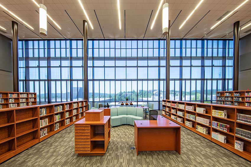
Photo courtesy of Kawneer
The interior of the new Fayetteville High School in Fayetteville, Ark., is illuminated by 28,000 square feet of curtain wall and 14,000 square feet of storefront glass, creating an open, airy design that helps foster a healthy environment for students and teachers.
Thermal Bridging in the Codes
Model energy codes typically address the performance of individual components in the building envelope. This includes the U-factor and solar heat gain coefficient of fenestration products as well as the R-value of opaque wall construction and roofing assemblies.
Model energy codes typically have not addressed the intersections of these components or penetration of the insulation; however, as they increase in overall stringency, some codes are beginning to address thermal bridging. For example, the Seattle Energy Code increases the amount of continuous insulation required in opaque wall construction based on percent area of metal penetrations compared to a wall with minimal metal penetrations (or thermal bridging). Energy codes in Vancouver and New York City require that thermal bridging details be identified on drawings and be accounted for in all performance modeling.
Most notably, ASHRAE 90.1 has been working on comprehensive new requirements to mitigate thermal bridges in many areas including roof edges, parapets, intermediate wall edges, balconies, masonry shelf angles, and the wall-to-fenestration intersection. These requirements will apply to colder regions (ASHRAE’s climate zones 4-8) and are anticipated to be included in the 2022 edition of ASHRAE 90.1, which will also be referenced in the 2024 International Energy Conservation Code (IECC).
How to Account for Thermal Bridges
The energy codes account for thermal bridges in two ways: simple prescriptive strategies and more complex modeling.
The simple approach can be deduced to a basic concept of a “thermal line” or “thermal plane.” Just as designers and engineers look for a continuous line connecting the constructions to form the primary air and water barriers, they should also now look to construct a continuous thermal line connecting the insulating materials across the transition details from fenestration to surrounding construction to create a “thermal barrier” between components. This results in different simple prescriptive strategies, shown in the diagrams pictured.
Strategies to Consider
For fenestration assemblies, whether a punched opening window or a curtain wall, the concept of a “thermal line” leads to the ideal scenario: alignment of the insulating glass units, thermal breaks within the frame, and insulation in surrounding construction without any significant bypasses. This ideal is not always possible when considering the many functional design requirements regarding structural support, water management, etc. However, better alignment will generally result in less thermal heat loss and an improved (lower) psi-factor.
The simplified prescriptive requirements proposed for ASHRAE 90.1 also try to encourage this practice of alignment and/or a continuous thermal line as much as possible. ASHRAE 90.1’s primary requirement is to align the glazing layer within 2 inches of the wall continuous insulation (e.g. mineral wool or insulating foam board), or within 2 inches of the exterior side of the cavity insulation where there is no continuous insulation. Ideally, thermal breaks within the frame are also aligned with the glazing, and the benefit from doing so will be reflected in the lower U-factor rating for the product.
Aligning the glazing system and the wall insulation is not always possible because of functional considerations such as structural design or simply for design aesthetics. Therefore, ASHRAE 90.1 also includes other options for recessed windows or offset construction. In that case, the goal is to continue the thermal line from the continuous insulation to the window framing, covering any exposed area with insulating material with R-value greater than 3 or thermal conductivity less than 3.0 Btu·in/h·ft2·°F (this would also include the option to mount the fenestration within a wood buck). It is not required that the insulation be under the frame, as careful consideration must be given to the attachment and support of the window, as well as proper water drainage.
In all cases, the intent is to maintain a continuous thermal line, as much as possible, to minimize interruption of the thermal line, thus creating “thermally bridged” details. However, there are many other issues that must also be considered at the same time.
More from the Design Guide
Download the complete design guide at glass.org/store for definitions of the two thermal bridging characterizations, linear and point; a breakdown of complex thermal bridging modeling; diagrams and photography depicting thermal bridging concepts; and strategies for edges and perimeters. The guide also explores the responsibility of designers to indicate thermal lines in construction drawings, and the responsibility of fenestration industry companies to provide an overall energy rating for a glazing system.
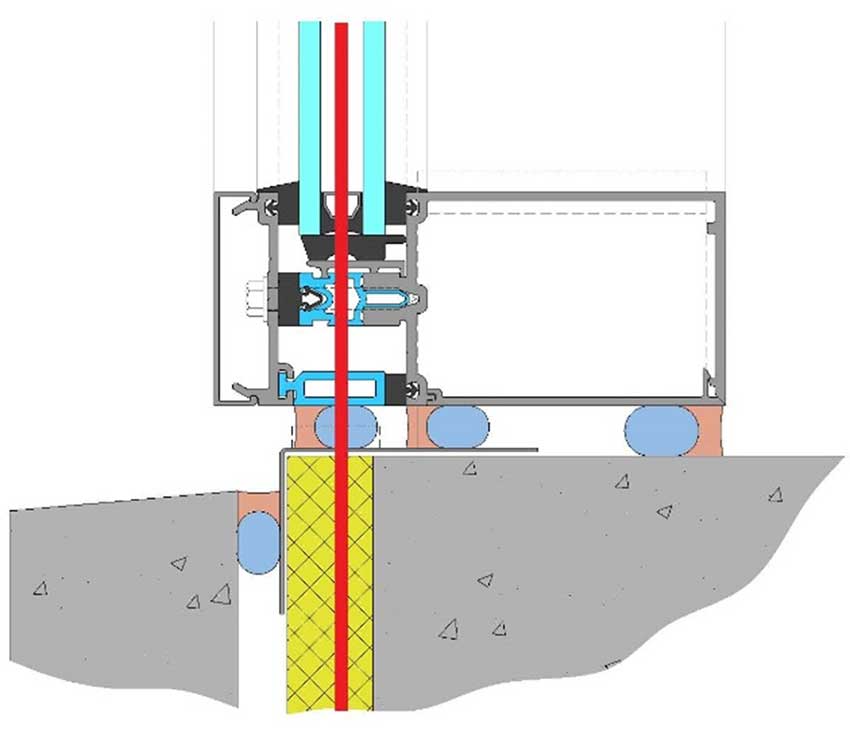
Image courtesy of National Glass Association
Efficient: Well-aligned glazing without conductive bypasses (thermal line illustrated in red).
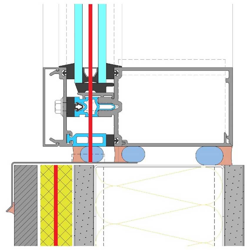
Image courtesy of National Glass Association
Regular: Misaligned glazing and minor conductive bypasses (thermal line illustrated in red).
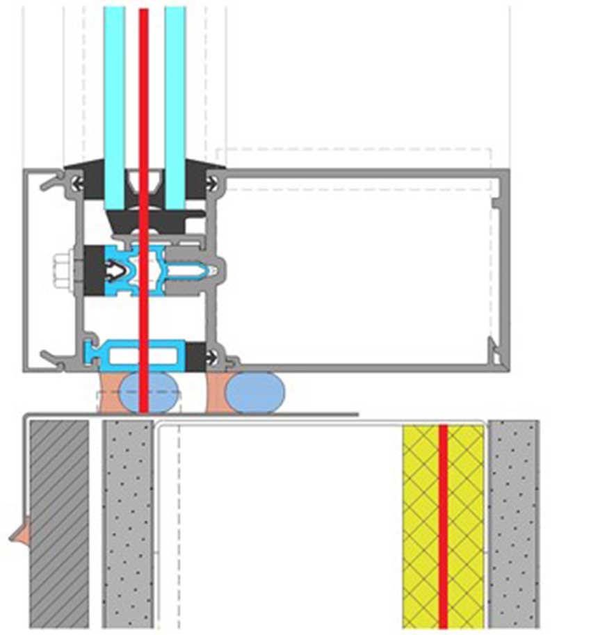
Image courtesy of National Glass Association
Poor: Cavity-insulated and conductive bypasses (thermal line illustrated in red)
The energy codes account for thermal bridges in two ways: simple prescriptive strategies and more complex modeling.
The high-performance facade equation is a challenge to solve. Design and project teams must weigh a myriad of factors to develop facade systems that meet next-level energy efficiency requirements, optimize whole-building performance, provide a healthy and comfortable environment for occupants, achieve increasingly important sustainability and carbon-reduction goals, meet budget, and more.
Photo courtesy of Takuji Shimmura
The BNP Curve in Paris features a more than 100,000-square-foot facade that allows the interior to be flooded with natural daylight. The insulating glass includes transparent and highly selective solar control glass from Saint-Gobain and warm-edge 16-millimeter Super Spacer Triseal Premium Black Plus from Edgetech/Quanex Building Products. The architect was Chartier Dalix Architects.
The good news for the building industry is that glass and glazing technologies exist to meet even the most stringent performance goals. “We can get to the point where the facade glazing systems can be better than the insulating opaque wall for any location, any orientation, any glass area,” according to Stephen Selkowitz, principal, Stephen Selkowitz Consultants, affiliate, Lawrence Berkeley National Laboratory, speaking during a presentation at the January NGA Glass Conference: Long Beach. However, meeting the wide-ranging goals for performance comes with mighty challenges. “This is not easy,” and it can be expensive, says Selkowitz.
The National Glass Association and Glass Magazine’s 2022 All About Glass & Metals: Guide for Architects takes a closer look at three essential elements to the high-performance facade equation. Part 1: Performance, explores the often-overlooked topic of thermal bridging in the facade; Part 2: Products, looks at innovations in insulating glass technologies; Part 3: People, considers balancing daylighting and glare to optimize occupant comfort and wellness; and Part 4: Payback, answers three key performance cost-benefit questions.
This article is part of the National Glass Association’s and Glass Magazine’s in-depth All About Glass & Metals series for architects and specifiers. The complete series also addresses considerations for protective glazing, interior glass, glass and glazing specifications, complex facades, and more.
PART 1: PERFORMANCE
THE IMPORTANCE OF THERMAL BRIDGING
“Thermal bridging is a big deal. It is the silent degrader,” said Helen Sanders, leader in strategic business development for Technoform, during the meeting of the energy group of the NGA Fabricating Committee during the NGA Glass Conference: Long Beach held in January.
Thermal bridging occurs when building exterior cladding or structural components with higher thermal conductivity penetrate or bypass insulation, thus creating a path of least resistance for heat transfer. For example, a steel beam or balcony penetrating the wall insulation will create a path for heat transfer. This pathway could lead to heat loss and decreased energy efficiency as well as potential cold points that can lead to condensation within the building envelope on exposed, interior surfaces.
“We’re not talking about thermal bridging in the frame. That is accounted for with U-factor,” described Tom Culp, owner of Birch Point Consulting, during the conference. “This [is] about how [heat transfer] bypasses insulation in a building. … It’s about alignment between the wall and the windows.”
In wall assemblies, metal penetrations can significantly reduce the effective R-value of the wall insulation. For fenestration assemblies, the potential for thermal bridges may occur where the window framing meets the surrounding wall if the surrounding insulation layer is bypassed.
Source: Adapted and excerpted from the “Thermal Bridging Considerations at Interface Conditions Design Guide,” published in January by the National Glass Association.
Photo courtesy of Kawneer
The interior of the new Fayetteville High School in Fayetteville, Ark., is illuminated by 28,000 square feet of curtain wall and 14,000 square feet of storefront glass, creating an open, airy design that helps foster a healthy environment for students and teachers.
Thermal Bridging in the Codes
Model energy codes typically address the performance of individual components in the building envelope. This includes the U-factor and solar heat gain coefficient of fenestration products as well as the R-value of opaque wall construction and roofing assemblies.
Model energy codes typically have not addressed the intersections of these components or penetration of the insulation; however, as they increase in overall stringency, some codes are beginning to address thermal bridging. For example, the Seattle Energy Code increases the amount of continuous insulation required in opaque wall construction based on percent area of metal penetrations compared to a wall with minimal metal penetrations (or thermal bridging). Energy codes in Vancouver and New York City require that thermal bridging details be identified on drawings and be accounted for in all performance modeling.
Most notably, ASHRAE 90.1 has been working on comprehensive new requirements to mitigate thermal bridges in many areas including roof edges, parapets, intermediate wall edges, balconies, masonry shelf angles, and the wall-to-fenestration intersection. These requirements will apply to colder regions (ASHRAE’s climate zones 4-8) and are anticipated to be included in the 2022 edition of ASHRAE 90.1, which will also be referenced in the 2024 International Energy Conservation Code (IECC).
How to Account for Thermal Bridges
The energy codes account for thermal bridges in two ways: simple prescriptive strategies and more complex modeling.
The simple approach can be deduced to a basic concept of a “thermal line” or “thermal plane.” Just as designers and engineers look for a continuous line connecting the constructions to form the primary air and water barriers, they should also now look to construct a continuous thermal line connecting the insulating materials across the transition details from fenestration to surrounding construction to create a “thermal barrier” between components. This results in different simple prescriptive strategies, shown in the diagrams pictured.
Strategies to Consider
For fenestration assemblies, whether a punched opening window or a curtain wall, the concept of a “thermal line” leads to the ideal scenario: alignment of the insulating glass units, thermal breaks within the frame, and insulation in surrounding construction without any significant bypasses. This ideal is not always possible when considering the many functional design requirements regarding structural support, water management, etc. However, better alignment will generally result in less thermal heat loss and an improved (lower) psi-factor.
The simplified prescriptive requirements proposed for ASHRAE 90.1 also try to encourage this practice of alignment and/or a continuous thermal line as much as possible. ASHRAE 90.1’s primary requirement is to align the glazing layer within 2 inches of the wall continuous insulation (e.g. mineral wool or insulating foam board), or within 2 inches of the exterior side of the cavity insulation where there is no continuous insulation. Ideally, thermal breaks within the frame are also aligned with the glazing, and the benefit from doing so will be reflected in the lower U-factor rating for the product.
Aligning the glazing system and the wall insulation is not always possible because of functional considerations such as structural design or simply for design aesthetics. Therefore, ASHRAE 90.1 also includes other options for recessed windows or offset construction. In that case, the goal is to continue the thermal line from the continuous insulation to the window framing, covering any exposed area with insulating material with R-value greater than 3 or thermal conductivity less than 3.0 Btu·in/h·ft2·°F (this would also include the option to mount the fenestration within a wood buck). It is not required that the insulation be under the frame, as careful consideration must be given to the attachment and support of the window, as well as proper water drainage.
In all cases, the intent is to maintain a continuous thermal line, as much as possible, to minimize interruption of the thermal line, thus creating “thermally bridged” details. However, there are many other issues that must also be considered at the same time.
More from the Design Guide
Download the complete design guide at glass.org/store for definitions of the two thermal bridging characterizations, linear and point; a breakdown of complex thermal bridging modeling; diagrams and photography depicting thermal bridging concepts; and strategies for edges and perimeters. The guide also explores the responsibility of designers to indicate thermal lines in construction drawings, and the responsibility of fenestration industry companies to provide an overall energy rating for a glazing system.
Image courtesy of National Glass Association
Efficient: Well-aligned glazing without conductive bypasses (thermal line illustrated in red).
Image courtesy of National Glass Association
Regular: Misaligned glazing and minor conductive bypasses (thermal line illustrated in red).
Image courtesy of National Glass Association
Poor: Cavity-insulated and conductive bypasses (thermal line illustrated in red)
The energy codes account for thermal bridges in two ways: simple prescriptive strategies and more complex modeling.
PART 2: PRODUCTS
NEW IGU TECHNOLOGIES FOR CARBON REDUCTION AND NET-ZERO ENERGY
The last year has witnessed increasingly ambitious plans from organizations on the global, national, and state levels to meet carbon-neutral, net-zero goals in the next several decades. These plans look at “how we get to 2030, 2040, 2050 with some variant of carbon neutral, or net zero, or half reductions in carbon,” according to Stephen Selkowitz, principal, Stephen Selkowitz Consultants, affiliate, Lawrence Berkeley National Laboratory, speaking during the NGA Glass Conference: Long Beach.
To reduce carbon emissions and meet these benchmarks, the building sector must be addressed. “Buildings are about 50 percent of the problem [with emissions] when you look at embodied energy and carbon in construction,” Selkowitz says. “If we’re going to solve the big-picture global and national energy and carbon problems, buildings are going to have to be part of the solutions…And windows are a big part of this.”
Source: Based on a presentation at the NGA Glass Conference: Long Beach by Stephen Selkowitz, principal, Stephen Selkowitz Consultants, affiliate, Lawrence Berkeley National Laboratory.
Opportunities of Retrofit
Window performance improvements are often focused on new construction. However, Selkowitz says the existing building stock provides the largest opportunity for performance improvements on a wider scale.
“If we’re going to get to 2050 [emissions goals], we have to address existing buildings. We can’t build our way out of this with new construction. Something like 50 percent or more of buildings that will exist in 2050 are already here now, and most of them are single- or double-glazed. So, we need to be thinking about how we retrofit,” Selkowitz says.
Consider, if all existing commercial windows in the United States were replaced with highest-performance integrated facade systems, the market would go from a cost of $20 billion a year to a savings of $15 billion a year, says Selkowitz. “This is if you can magically change every building in the country, which isn’t going to happen,” he says. But it begins to demonstrate the potential savings that are possible when the industry focuses on existing buildings.
Highly Insulating Glazing Solutions
The glass industry offers numerous solutions to improve the performance of insulating glass in buildings. “Can we make the IGUs better thermally? We can play with coatings, with glazings, with the system, and to some degree with the whole building,” Selkowitz says.
Existing
Double glazing with gas fill represents about 89 percent of the market today. Triple and quad IGUs are in the market, but are often used only in the coldest climate zones. In the United States “in residential, triples have about 3 percent market share. I’m guessing it’s less in the commercial space,” Selkowitz says.
Emerging
Emerging IGU technologies include vacuum insulating glazing, VIG and thin triples, which consist of double glazing with a thin-glass interior lite. The technologies can be paired with additional improvements, as well. Low-emissivity coatings can be applied to VIG and to thin triples, with thin triples featuring up to two low-e coatings, and gas fill can be added to the thin triples.
“VIG has been around in a limited form for 20 years. There are some very good products out now, but there’s not a lot of market impact,” Selkowitz says. “There is a lot of new buzz in terms of hybrid [VIG], new R&D, new generation. That will hopefully make [the products] cheaper.”
Thin triples look to achieve the next-level performance of traditional triple IGUs, but deliver a product that is not as heavy, not as wide, and will fit in the existing pocket of a normal sash. “With the thin triple, you get about an R-8 center of glass,” says Selkowitz. “You’ve got a slightly larger glass package, you can put two pieces of thin triple and get R-14…This is great news. You can get an R-14 center of glass with a VIG, or with a quad glazing.”
Future
Looking ahead, Selkowitz identifies promising future IGU solutions, including two low-e vacuum hybrid units, which is an IGU that features VIG on one side of the unit. Insulating Aerogel is also promising.
“The [Department of Energy] has been putting a lot of research dollars into Aerogel in the last couple of years,” Selkowitz says. There are products out now that are highly insulating, but they are “granular diffusing,” which means they have a hazy white translucent appearance. “If you want clear Aerogel, you’ll have to wait a bit longer,” he says.
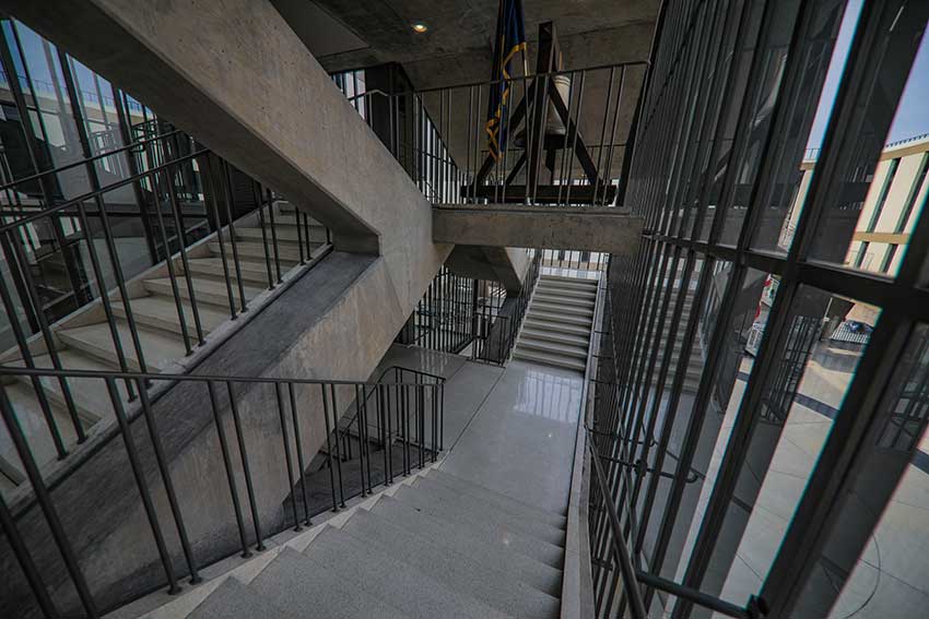
Photo courtesy of National Glass Association
Vacuum-insulating glazing was critical to the restoration of the 1955 Eero Saarinen-designed “Bird Cage” at the Milwaukee County War Memorial. The Bird Cage is a double cantilever staircase enclosed with a glass and steel curtain wall. The project features Pilkington Spacia VIG from NSG Group, which offers thermal performance improvements and a thin profile that allowed the glass to be incorporated into the original, restored curtain wall system. The restoration project architect was HGA Architects and Engineers, the preservation consultants, Preserve LLC, and the glazing consultant and contractor, Restoric LLC.
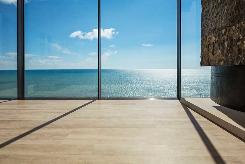
Image courtesy of AGNORA
PART 3: PEOPLE
DAYLIGHTING + VIEWS
In November 2021, plans for an 11-story, 1.68 million-square-foot dormitory building at the University of California Santa Barbara were revealed and quickly drew backlash from numerous leaders in the design community. The project, Munger Hall, designed by billionaire investor Charlie Munger, has been called “dangerous,” “a monstrosity,” “a social and psychological experiment with an unknown impact.”
The primary target of criticism is the designer’s bold choice to greatly limit access to natural daylighting and views for the building’s occupants. While the dorm is intended to house 4,500 students, 94 percent of them would not have access to windows in their compact single-occupancy bedrooms.
How could such a proposal find traction when study after study shows that humans require access to both natural daylighting and views to thrive? To ensure that people can live, work, learn and play in healthy, high-performing environments, all spaces they inhabit—from homes to schools, and offices to shopping malls—must provide ample access to natural daylight and views.
Part 3 of this article, the People section, provides an overview of effective daylighting solutions, and offers expert insights on the importance of daylighting for occupant health and wellness.
Source: Adapted and excerpted from the NGA Daylighting Glass Technical Paper, available at glass.org/store, and from the Glass Magazine article, “Daylighting + Views,” from the January/February 2022 edition.
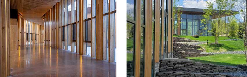
Photo courtesy of Jana Bannan Photography
The JST Production and Engineering Center in Harrisburg, Pa., touts a sustainable design using laminated timber, deep roof overhangs, flow-through ventilation and a floor-to-ceiling glass exterior, composed of 40 percent glass. The facade features a new hybrid aluminum and wood veneer framing system. YKK AP created a 3-inch veneer wall system that would match the existing size of the timber beams; a new die was manufactured to do so. A horizontal aluminum tube was then set above and below the casement window, so that YKK AP’s YES SSG TU Vented Window could be set into the curtain wall pocket for easy installation. The design team included Ryuichi Ashizawa Architects and architect of record Arcari+Iovino Architect.
Maximize Daylight, Minimize Discomfort and Glare
Daylight has qualities that cannot be replicated by electrical light. The changing intensity, direction and color of natural light connect building occupants to the weather, season and time of day. Views through windows can stimulate the well-being and productivity of building occupants. With careful design and daylighting controls, daylighting can also substantially reduce lighting energy use.
The potential for daylighting and views is largely a function of orientation, window placement and window area, as well as the windows’ visible transmittance. However, daylight admission must be balanced with glare control and thermal comfort.
If solar radiation causes discomfort and glare, this may not only mean an unwelcome side effect to daylighting. It can actually eliminate its benefits. As pointed out by officials from Lawrence Berkeley National Laboratory, “the classic problem that plagues side-lit perimeter spaces is that occupants sitting nearest the window will lower the shades to avoid thermal discomfort from direct sun or visual discomfort from glare.” Often, shades are left lowered for long periods of time, which can eliminate much of the useful daylight and view.
The task is to reduce contrasts and allow daylight to reach deeper into the space. As a general rule of thumb, direct sun should be blocked from falling on occupants and task surfaces, especially if computers are involved. This is partly a matter of interior design and shading devices, but glazing design can already achieve much on its own. For instance, glazing can be separated into glazing for daylighting and glazing for views while daylight is redirected by means of light shelves. Top lighting fenestration such as roof monitors can be another means of controlled daylight access. Advanced glazing for daylight control is available with electrochromic coatings or between-glass blinds. Finally, orienting glazing along an east-west axis typically reduces the potential for glare and allows for more even light conditions throughout the day.
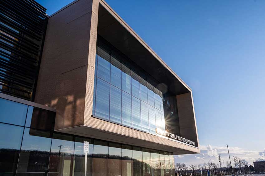
Photo courtesy of AGNORA
The Marotta Family Innovation Complex at Niagara College in Ontario, Canada, features oversized IGUs in the main office, which face a southern direction to maintain constant sun exposure. The glass units feature Pilkington OptiWhite on the inboard lite and a low-iron option. The makeup properly controls heat gain and visible transmission values to create the most comfortable working environment.
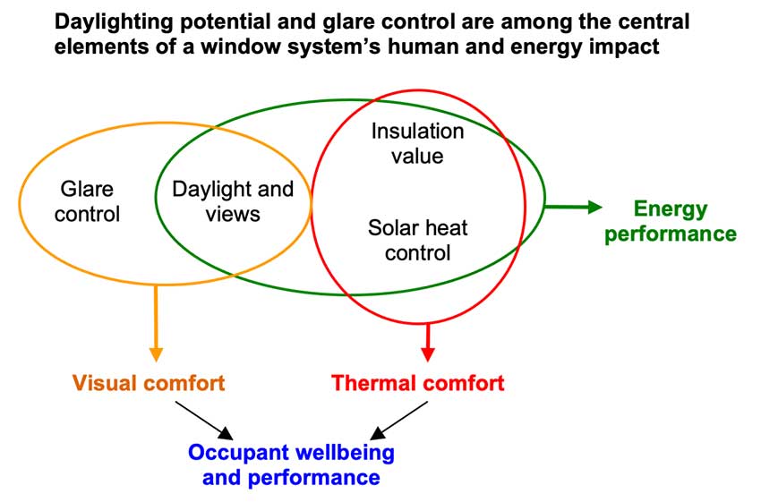
Image courtesy of National Glass Association
Daylighting design remains an art as much as a science. One reason is that discomfort glare is difficult to quantify and predict since it is highly dependent on the occupant’s direction of view and task. Few studies have been conducted to derive models that could help with such predictions. Add to this the unpredictability of occupant behavior (e.g. in terms of operating interior shading devices) and it becomes apparent that in many cases experience is still the surest guide.
In addition, some of the most effective daylighting strategies include a combination of shading, surface coloring and interior design features that is rather complicated to model in its entirety. Scientific tools can be a great help, but what really allows designers to push the envelope is innovation informed by experience.
Finally, good daylighting design also relies on the art of teamwork among the different disciplines. For example, electrical and lighting engineers should be involved early in the process of daylighting design so that architects can take their knowledge and experience into account.
The complexities of daylighting should not intimidate designers into ignoring its promises. Whether simple design tools or advanced strategies are used, any improvement in facade design for the purpose of daylighting can save energy as long as thermal performance is taken into account. Aside from energy savings, it is a central goal for architects and building owners to provide occupants with stimulating and comfortable work or learning spaces. With this goal in mind, priority attention to advanced glazing and facade design is well worth the effort.
More Daylighting Resources
Download the complete Daylighting Glass Informational Bulletin in the NGA's glass.org. The full document provides additional information on modeling options to simulate daylighting, links to resources on daylighting from the National Institute of Building Science, Laurence Berkeley National Laboratory and more. The NGA also developed the document, “Benefits of Decorative Glass in Daylighting Applications,” also available for download
Hear from the Experts
This section features leading voices in the industry, educating about the role of natural light and views on human health and performance, and discussing the essential role of glass in daylighting design. Read insights from Lisa Heschong, a leading daylighting researcher, and from the glass industry’s Adam Mitchell of AGNORA and Helen Sanders of Technoform
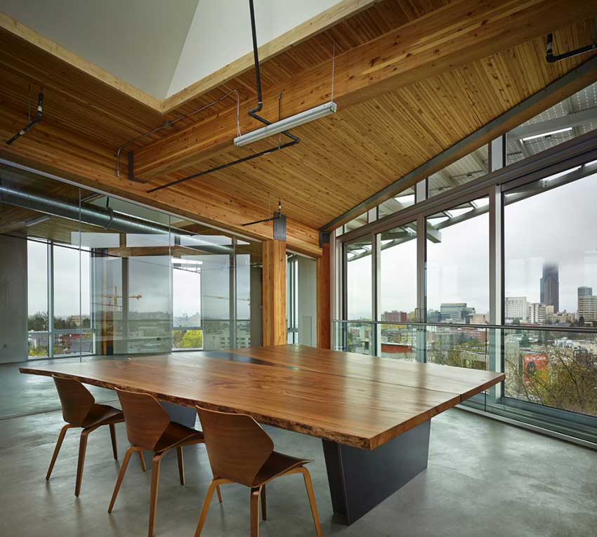
Photo courtesy of Benjamin Benschneider; Technoform
Daylighting design was a top priority for the 2013 net zero-designed Bullitt Center in Seattle. The design team relied on a daylighting simulation tool to help determine everything from window configurations to ceiling heights, according to Bullitt Center officials. The project features Technoform’s TGI-Spacer for Schüco curtain wall and operable window systems with Solarban 60 glass.
PART 4: PAYBACK
THREE BUILDING PERFORMANCE COST-BENEFIT QUESTIONS
The primary roadblock in adopting a high-performing glass product is cost. “Most of the time, [the products] are value-engineered out of a project,” says Urmilla Sowell, technical and advocacy director for the National Glass Association. However, the price tag for high-performance systems should be considered alongside the holistic costs of building construction and operations. Sources point to three primary areas to consider when weighing costs.
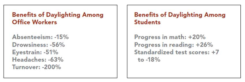
Image courtesy of National Glass Association
Sources: (absenteeism) independent studies from Lockheed Martin in California and ING Bank in the Netherlands; (turnover) study from Story County (Iowa) Human Services; (eyestrain, headaches and drowsiness) Department of Design and Environmental Analysis, Cornell University, “Worker Reactions to Electrochromic and Low-E Glass Office Windows;” (in schools) Heschong Mahone Group, “Daylighting in Schools: An Investigation into the Relationship Between Daylighting and Human Performance.”
How can glass and glazing cut down HVAC and lighting costs?
HVAC systems account for about 40 percent of total energy use in commercial buildings, according to the Department of Energy. Meanwhile, lighting systems capture about 16 percent of electricity costs. Building owners can offset costs in both areas through the use of high-performance glass and glazing products, and by maximizing natural daylighting.
“If we’re smart and do it right, we can reduce the size of HVAC. This is one of the most expensive parts of building. Reduce the size of the heating and cooling systems and take money saved and put it back into the facade,” says Stephen Selkowitz, retired senior advisor for building science and former group leader of the Windows and Envelope Materials Group in the Building Technology and Urban Systems Division at Lawrence Berkeley National Laboratory.
What is the Payback of Occupant Comfort?
Glass and glazing—with benefits of daylighting, views, access to nature and more—are essential to occupant wellness. Numerous studies have demonstrated a relationship between glass and improved test scores among students, accelerated healing among hospital patients, and increased productivity and fewer absences among workers.
“An estimated 85 to 90 percent of our time is spent indoors. But we know our bodies need to be outside—we need to have that type of environmental connection to be happy,” says Sowell.
“There is a renewed appreciation of glass and glazing in terms of people and how they work and live,” adds Selkowitz.
When the human costs of a building are factored into building design and operations, the value of glass and glazing products greatly increases. “The most costly pieces [of building operations] are people,” says Selkowitz. “The cost of people is 10 times construction costs and 100 times operating costs.”
How will performance disclosures and penalties affect owners?
A growing number of cities and states are adopting energy performance requirements beyond those in the national codes. “There is a new urgency in the codes—strong, quick action in response to climate change,” says Tom Culp, owner of Birch Point Consulting and energy code consultant for the NGA.
Legislation, such as Local Law 97 in New York City and Washington State HB 1257, are beginning to require post-occupancy building commissioning—performance measurements—with penalties for buildings that don’t meet requirements. “It’s essentially a carbon tax if you’re not building up to minimum levels,” Culp says. “This changes the economics.”
“The codes with proposed penalties [coming] down the road should encourage building owners to say, ‘hey, this really is a more economical approach in the long run.’ Otherwise, it’s a pay me now or pay me later situation,” says Charlie Boyer, principal, Boyer & Associates, and consultant, VIG Technologies. “You might be installing something now, but five to 10 years later you’ll have to pay for new installations or upgrades. The time is coming to advance these technologies.”
Numerous other jurisdictions are moving toward performance benchmarking/disclosures for buildings. Culp points to legislation in dozens of cities in all parts of the country, from Seattle, to Boston, to Austin, Texas, to St. Louis, Missouri. Such disclosure requirements could affect real estate prices, incentivizing owners to prioritize performance, even without associated penalties.
Katy Devlin, is the associate publisher and editor in chief of Glass Magazine, published by the National Glass Association