This CE Center article is no longer eligible for receiving credits.
Energy Conserving Fenestration Systems
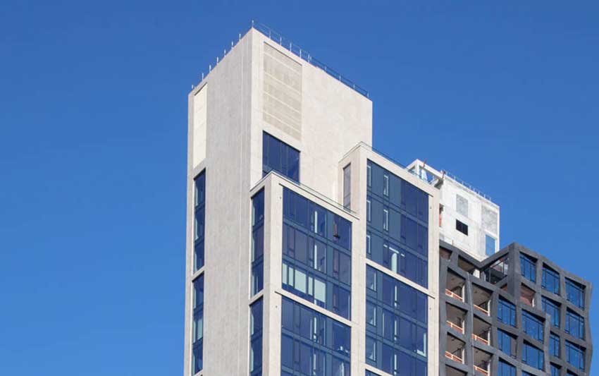
Fenestration usually figures prominently in most building facades and the key to a successful installation is a manufactured frame to hold the fenestration in place, secured to the rest of the building. The material of choice is usually an aluminum frame or support system. Such aluminum frames are lightweight but inherently strong, can avoid rust or corrosion, are rather economical to work with, and are available in a variety of colors and finishes. Nonetheless, aluminum is also an excellent conductor of heat which makes its use on building facades a concern when addressing energy conserving design and compliance with energy codes – the aluminum acts as a thermal bridge between inside and outside. This is true in both cold and warm climates as well as extreme weather conditions.
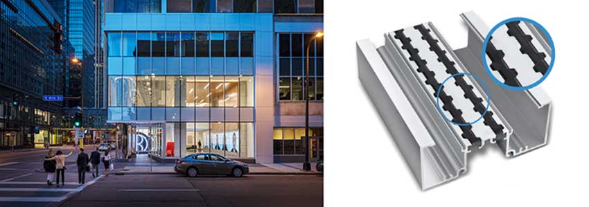
Photo courtesy of Azon; Paul Cosby Architectural Photography
The aluminum framing used in fenestration systems include tested and proven thermal breaks or barriers to improve thermal performance while maintaining structural integrity and overall performance.
Manufacturers of aluminum framing systems for fenestration continue to develop products that maintain their structural integrity while offering improved thermal performance. The key component is the addition of a thermal break or barrier in the aluminum frames, usually in line with the location of glass or other glazing in the frame. The intent is that the interior and exterior portions of the frame are separated with a structurally rigid but less thermally conductive material. The details of how that break is created and the choice of materials used are what tend to differentiate various products from each other.
Commonly there are three choices of material used as thermal breaks or barrier material in commercial fenestration systems, namely, vinyl plastic, polyamide nylon or polyurethane polymer. Each have different thermal and structural properties so finding the best choice is a combination of understanding those properties and the way they work with the details of a particular aluminum frame profile.
Improved Thermal Breaks
Polyurethane has received a good bit of attention as a thermal barrier material in aluminum frames since it can provide superior thermal performance to other choices. For example, in at least one frame comparison, a polyamide thermal barrier was used to achieve a U-factor of 0.39 but required a 24 mm gap to do so. By contrast, a polyurethane barrier was used to also achieve a U-factor of 0.39 but only required a 15.8 mm gap. A smaller gap can mean better structural performance of the frame and possibly thinner overall profiles of products. Hence, achieving better thermal performance in thinner breaks has advantages when seeking to create better fenestration products that allow better sightlines, more structural integrity, and durability.
The most effective way to create a thermal break is referred to as a “pour and de-bridge” process. An extruded aluminum profile is designed with a strategically placed U-shaped channel in the middle of the frame piece. Once ready, the thermal barrier material is installed using specialized equipment designed for this purpose. If polyurethane is used, it is literally poured in liquid form into the pre-designed channel. Within minutes the polyurethane solidifies into a very strong structural polymer. Then the metal thermal bridge is cut and removed from the bottom of the channel to produce a true, non-metal-to-metal structural thermal barrier. This pour and de-bridge method is suitable for withstanding demanding climates and conditions with high performance requirements in terms of impact resistance, shear strength and heat distortion.
Architectural Glass
Glass is recognized by many architects as one of the most popular and versatile building facade materials in use while also providing a dramatic aesthetic. Additionally, glass can provide daylit interiors that boast a range of benefits, such as improved occupant mood and productivity, a sense of connectivity to the outdoors, decreased use of artificial light and energy, stunning views, and excellent color transmission. But the design beauty of glass is pointless if the people inside the building are uncomfortable or if energy inefficiency makes the building too expensive to operate.
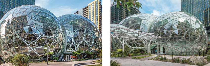
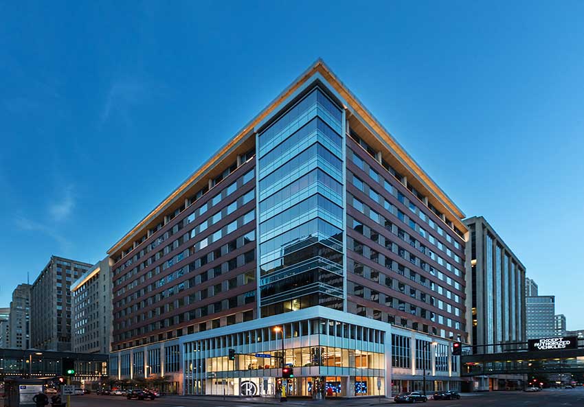
Photo courtesy of Vitro Architectural Glass
Advanced low-e coatings on low-iron glass produces desirable, energy-efficient spaces, such as the spheres at Amazon Headquarters designed by NBBJ in Seattle, Washington.
In response to the energy needs, low-emissivity (low-e) glass coatings have been used that minimize the amount of ultraviolet and infrared light that can pass through glass without compromising the amount of visible light that is transmitted. A microscopically thin transparent coating allows low-e glass to reflect exterior heat in warm temperatures and hold in heat during cold temperatures. For situations where the highest amount of visible light or clarity of views are sought, low-iron glass is often used in an insulating glass unit (IGU) to receive the low-e coating. Traditional glass carries a green tint which is amplified as the thickness of the glass increases. Low-iron glass makes that tint much less pronounced.
Energy-efficient, low emissivity (low-e) glass products have been used on hundreds of sustainable projects worldwide, yet even with all these accomplishments, glass manufacturers continue to innovate and offer new product options.
Vacuum Insulating Glass (VIG)
One of the latest architectural glass innovations is Vacuum Insulating Glass which consists of two lites of glass separated by a metal seal and a vacuum space between the lites. With center of glass R-values of R14 and higher, this advanced glazing can deliver thermal performance much closer to an opaque insulated wall than a traditional window. VIG units enhance the performance of any glass configuration by effectively blocking thermal transmission, delivering thermal insulation performance that is two to four times better than conventional insulating glass and up to 14 times better than monolithic glass. The slim construction and light weight of VIG units allows them to be incorporated into virtually any traditional glazing system, window frame or curtainwall application. The heat transfer coefficient of VIG remains constant regardless of whether it’s mounted horizontally or with an angle, making it suitable for installation at any position around the building.
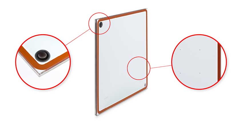
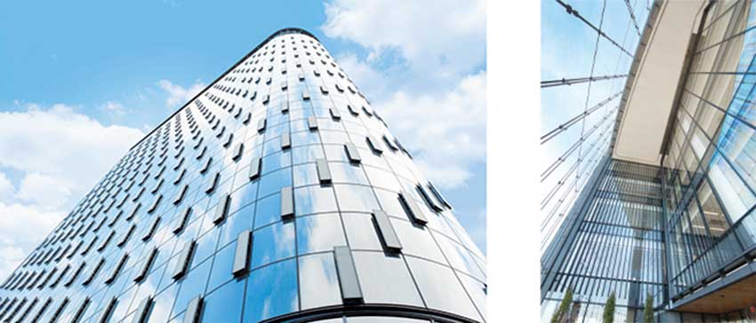
Photo courtesy of Vitro Architectural Glass
A couple of important components of vacuum insulating glass that are noticeably different from conventional insulating glass units are the vacuum port and the micro support pillars shown above.
One of the major benefits of VIG is that it allows for generous, aesthetically pleasing window-to-wall ratios without having to sacrifice insulation performance or occupant comfort. The extraordinary R-values of VIG deliver energy savings and reduced carbon emissions by way of lower BTU usage in buildings where these larger glass expanses are used.
In addition to energy conservation, the high vacuum chamber can effectively eliminate condensation on interior and exterior glass surfaces. The outstanding insulating capacity of VIG ensures interior glass surfaces remain free of condensation even when the outdoor temperature falls to -58° F. VIG also offers higher resistance against thermal expansion or contraction caused by temperature or other differences even if the elevation of the location where it’s used is largely different from where it’s manufactured. Further, the high vacuum chamber of VIG effectively blocks sound transmission with a weighted sound isolation from 39dB to 43dB, generating a remarkable soundproof effect against mid and low frequency noises such as traffic.
Architectural Louvers
Architects typically rely on louvers for HVAC systems, not only to provide needed airflow while protecting systems and ductwork from water damage, but also to create exciting and distinct exteriors. Louvers also create resistance to rainwater or hurricane-type winds, reducing the need for costly repairs to air handling equipment and building interiors from potential weather damage.
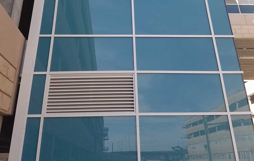
Photo courtesy of Airolite
Louvers can be incorporated into glazed curtain wall systems as long as the performance requirements, governing codes, and glazing system details are coordinated.
There are a number of common issues or questions that can come up regarding their use, which are touched on as follows.
Free Area
The free area of a louver is defined as the total louver face area, minus the airflow restrictions (blades and frame) through which air can freely pass within the openings. Free area is a major determinant of a louver’s performance capabilities. Louver frame depth, component profiles, louver blade spacing, and louver blade angle all play a role in determining the louver free area. Architects often become concerned about whether or not there is enough free area in a particular project and if free area of louvers can be increased (presumably to keep total louver area to a specific size). The best way to discern answers to these questions is to consult with manufacturers literature or representatives since it is their products that will be the ones designed, sized, and tested to produce particular results.
The public view of buildings is their facade, so it is natural to focus on the appearance or the visible skin. However, facades need to perform for weatherability, energy conservation, and durability over time. Balancing the appearance and the performance of facades requires a total design process that is often most successful when it includes a combination of design and construction professionals working with product manufacturers. Together, the design, constructability, fabrication options, and connection details can be better understood and more efficiently coordinated. At the same time, important issues such as sustainability, cost, and maintenance can be properly addressed. This course touches on all these issues and looks at some of the latest products that are being used to combine great looks with excellent performance.
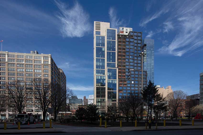
Photo courtesy of Neolith
Creating successful building facades requires attention not only to the appearance, but to the system of products and materials used to assure the best performance.
Sintered Stone Surface Cladding
The outermost skin of a facade system is typically some type of surface cladding. While many different conventional products are available, a lightweight, innovative choice can be found in all natural, time-proven, sintered stone panels. Sintering refers to the atomic diffusion of particles which occurs most quickly at higher temperatures. Applying this to sintered stone produces a thin, lightweight, and very strong material with properties like, but better than, porcelain ceramic tile. The primary manufacturing difference is that sintered stone products are made from selected natural minerals and only the atmospheric humidity that they contain.
Sintered stone panels can provide many design options since it is offered with appearances resembling natural marble, steel, wood, and other materials in a wide range of colors. From a performance standpoint, it is a very dense, lightweight, and sustainably produced material. It is nonporous, resistant to scratches, resistant to high temperatures, easy to clean, resistant to UV rays, and 100 percent natural. It is also lightweight, recyclable, ultra-hygienic and resistant to bending.
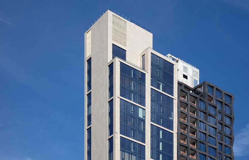
Photo courtesy of Neolith
Sintered stone panels are used on building facades to achieve elegant design appearances and high performance.
From a construction standpoint, the lightweight panels are easy to work with. They can be securely applied relatively quickly creating efficiencies in the construction process compared to other materials. Specifically, for facade systems, there are four common methods of attachment:
- Hidden System: This option consists of hidden supports using chemical elastic longitudinal mounting on vertical “T”-shaped or “L”-shaped profiles. The profile shape is dependent on whether they match the joints between sintered panels or if they are reinforcing the center of the joint.
- Ventilated System: This system consists of a metallic self-supporting substructure for ventilated facades, designed to support different formats and thicknesses. It has been developed for sintered stone facades based on a visible mechanical fastening system composed of brackets, vertical “T” or “L”-shaped profiles and safety clips upon which the cladding system rests.
- Hybrid System: A combination system uses a mix of hidden longitudinal fastening system (chemical and mechanical), which works by the compression exerted by the system on the back of the sintered stone panels.
- Thin-Set System: Thin-set applications are among the most common facade application systems. Sintered stone provides a very light weight solution making this very suitable for many situations.
A recent advancement in this material is the addition of an aqueous and titanium dioxide nanoparticle-based treatment that is sprayed on to create a photocatalytic, self-cleaning, and decontaminating effect. All building facades over time, become dirty and coated with contaminating agents, such as nitrogen dioxide, that are carried through the air. The nanoparticle-based treatment creates self-cleaning surfaces that also purify the air around the facade by means of two fundamental processes.
- Photocatalysis: When the treated surface enters into contact with sunlight (or some LED lights), the titanium dioxide particles are activated. The light energy is used to transform the moisture in the air into oxidizing agents which destroy nitrogen dioxide particles and contaminating agents and transform them into harmless water vapor and salt. This process is repeated millions of times per second until all contaminants are destroyed, meaning that the surface is constantly being self-cleaned.
- Superhydrophilicity completes the treatment action. Thanks to the high density of sintered stone, water expands on the surface evenly when it rains to drag and remove any remaining dirt particles. This leaves the surface completely clean without any water marks. Because of all these properties and characteristics, sintered stone has become an excellent solution for all types of facade projects, combining exquisite design options with high-performance functionality.
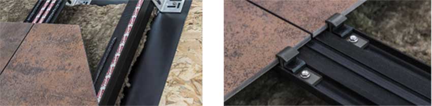
Photo courtesy of Neolith
Different types of mounting systems are available for sintered stone including concealed mounting and the use of exposed clips.
Aluminum Panel Trim
Not all cladding is the same, so it follows that not all methods of supporting cladding panels are the same. Similarly, different claddings have different capabilities for the edges of panels to be left uncovered or unprotected. This is particularly true if the cladding is porous, such as with wood, cement fiber boards, or some composite products. In these and other cases, some sort of trim is typically used around the perimeter of the cladding panels both to secure the edges in place and to protect the edges. While this trim can be made from wood, composite, or plastic based materials, a desirable alternative is the use of thin, extruded aluminum trim systems.
Trim Design
The design possibilities of using aluminum trim are extensive. Literally thousands of standard profiles are available that can either create a recessed reveal between cladding panels, be flush over the top surface, or can intentionally project outward to accentuate the lines of the design. The aluminum is available in a wide range of standard anodized or painted colors. Extruded aluminum trim can be provided in sizes and styles that work with multiple panels enabling architects to vary the material choices within their facade designs while keeping details that will have a similar language. Used in any of these ways, it has typically been shown to be less expensive with a more elegant look of clean lines than with other options.
For situations that require it, there is the option of working with a manufacturer to create custom trim profiles to suit the needs of a project. There is also the option of custom coloring for any standard or custom trim profile. With over 3,500 profiles and custom color matching available there are few design limits. Creativity is made easier with custom profiles and multi angle corners eliminating the need for cookie cutter designs. Similarly, installation is easier with the availability of two-piece profiles meaning less labor and quicker results.
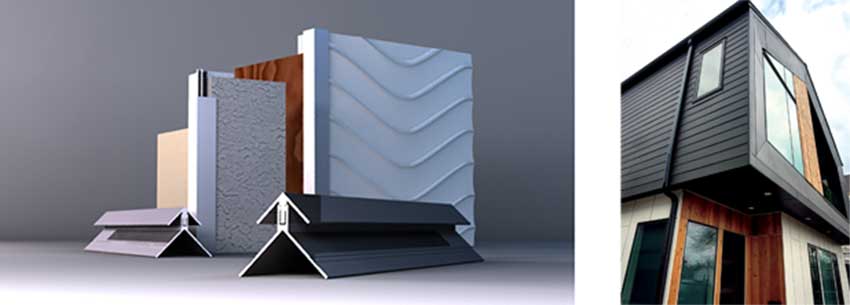
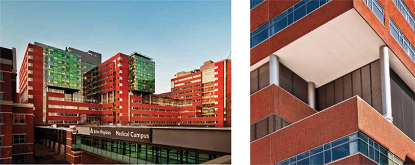
Photo courtesy of Tamlyn
Extruded aluminum trim can be used on interior wall surfaces to provide custom looks, durable protection, and easy-to-clean surfaces.
Trim Performance
Aluminum trim, in both one-piece and two-piece solutions, can be specified in common thicknesses and profiles to suit any of the lightweight cladding materials commonly in use. It is manufactured to work with virtually any lap siding, wood, fiber cement panels, composite panels, metal panels, and almost any other common building material. When used to hold the edges of exterior wall panels, or siding, it provides architects with a unique means to detail corners, vertical and horizontal joints, and material transitions with durability and integrity.
As a material, extruded aluminum is a common building material favored for its versatility, inherent strength, and durability. Through the use of recycled content, it is also a very sustainable material to use.
The installation of extruded aluminum trim is typically very straightforward. In particular, two-piece extruded aluminum profiles are recommended for greater construction efficiency in handling tougher detailing situations. The two-piece design permits application of the base part first and then installation of the cover cap afterwards. In tight fit situations this may be more efficient compared to using the standard trim pieces for inside or outside corners or for transitions. Due to the natural expansion and contraction of aluminum, all two-piece caps must be secured by adhesive or other means as approved by the manufacturer.
Overall, extruded aluminum trim is a proven and cost-effective solution for many different cladding options on facades.
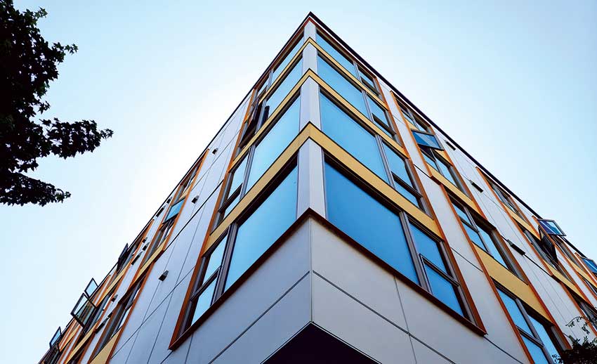
Photo courtesy of Tamlyn
Modern and contemporary designs can be created using either one-piece or two-piece aluminum trim products.
Energy Conserving Fenestration Systems
Fenestration usually figures prominently in most building facades and the key to a successful installation is a manufactured frame to hold the fenestration in place, secured to the rest of the building. The material of choice is usually an aluminum frame or support system. Such aluminum frames are lightweight but inherently strong, can avoid rust or corrosion, are rather economical to work with, and are available in a variety of colors and finishes. Nonetheless, aluminum is also an excellent conductor of heat which makes its use on building facades a concern when addressing energy conserving design and compliance with energy codes – the aluminum acts as a thermal bridge between inside and outside. This is true in both cold and warm climates as well as extreme weather conditions.
Photo courtesy of Azon; Paul Cosby Architectural Photography
The aluminum framing used in fenestration systems include tested and proven thermal breaks or barriers to improve thermal performance while maintaining structural integrity and overall performance.
Manufacturers of aluminum framing systems for fenestration continue to develop products that maintain their structural integrity while offering improved thermal performance. The key component is the addition of a thermal break or barrier in the aluminum frames, usually in line with the location of glass or other glazing in the frame. The intent is that the interior and exterior portions of the frame are separated with a structurally rigid but less thermally conductive material. The details of how that break is created and the choice of materials used are what tend to differentiate various products from each other.
Commonly there are three choices of material used as thermal breaks or barrier material in commercial fenestration systems, namely, vinyl plastic, polyamide nylon or polyurethane polymer. Each have different thermal and structural properties so finding the best choice is a combination of understanding those properties and the way they work with the details of a particular aluminum frame profile.
Improved Thermal Breaks
Polyurethane has received a good bit of attention as a thermal barrier material in aluminum frames since it can provide superior thermal performance to other choices. For example, in at least one frame comparison, a polyamide thermal barrier was used to achieve a U-factor of 0.39 but required a 24 mm gap to do so. By contrast, a polyurethane barrier was used to also achieve a U-factor of 0.39 but only required a 15.8 mm gap. A smaller gap can mean better structural performance of the frame and possibly thinner overall profiles of products. Hence, achieving better thermal performance in thinner breaks has advantages when seeking to create better fenestration products that allow better sightlines, more structural integrity, and durability.
The most effective way to create a thermal break is referred to as a “pour and de-bridge” process. An extruded aluminum profile is designed with a strategically placed U-shaped channel in the middle of the frame piece. Once ready, the thermal barrier material is installed using specialized equipment designed for this purpose. If polyurethane is used, it is literally poured in liquid form into the pre-designed channel. Within minutes the polyurethane solidifies into a very strong structural polymer. Then the metal thermal bridge is cut and removed from the bottom of the channel to produce a true, non-metal-to-metal structural thermal barrier. This pour and de-bridge method is suitable for withstanding demanding climates and conditions with high performance requirements in terms of impact resistance, shear strength and heat distortion.
Architectural Glass
Glass is recognized by many architects as one of the most popular and versatile building facade materials in use while also providing a dramatic aesthetic. Additionally, glass can provide daylit interiors that boast a range of benefits, such as improved occupant mood and productivity, a sense of connectivity to the outdoors, decreased use of artificial light and energy, stunning views, and excellent color transmission. But the design beauty of glass is pointless if the people inside the building are uncomfortable or if energy inefficiency makes the building too expensive to operate.
Photo courtesy of Vitro Architectural Glass
Advanced low-e coatings on low-iron glass produces desirable, energy-efficient spaces, such as the spheres at Amazon Headquarters designed by NBBJ in Seattle, Washington.
In response to the energy needs, low-emissivity (low-e) glass coatings have been used that minimize the amount of ultraviolet and infrared light that can pass through glass without compromising the amount of visible light that is transmitted. A microscopically thin transparent coating allows low-e glass to reflect exterior heat in warm temperatures and hold in heat during cold temperatures. For situations where the highest amount of visible light or clarity of views are sought, low-iron glass is often used in an insulating glass unit (IGU) to receive the low-e coating. Traditional glass carries a green tint which is amplified as the thickness of the glass increases. Low-iron glass makes that tint much less pronounced.
Energy-efficient, low emissivity (low-e) glass products have been used on hundreds of sustainable projects worldwide, yet even with all these accomplishments, glass manufacturers continue to innovate and offer new product options.
Vacuum Insulating Glass (VIG)
One of the latest architectural glass innovations is Vacuum Insulating Glass which consists of two lites of glass separated by a metal seal and a vacuum space between the lites. With center of glass R-values of R14 and higher, this advanced glazing can deliver thermal performance much closer to an opaque insulated wall than a traditional window. VIG units enhance the performance of any glass configuration by effectively blocking thermal transmission, delivering thermal insulation performance that is two to four times better than conventional insulating glass and up to 14 times better than monolithic glass. The slim construction and light weight of VIG units allows them to be incorporated into virtually any traditional glazing system, window frame or curtainwall application. The heat transfer coefficient of VIG remains constant regardless of whether it’s mounted horizontally or with an angle, making it suitable for installation at any position around the building.
Photo courtesy of Vitro Architectural Glass
A couple of important components of vacuum insulating glass that are noticeably different from conventional insulating glass units are the vacuum port and the micro support pillars shown above.
One of the major benefits of VIG is that it allows for generous, aesthetically pleasing window-to-wall ratios without having to sacrifice insulation performance or occupant comfort. The extraordinary R-values of VIG deliver energy savings and reduced carbon emissions by way of lower BTU usage in buildings where these larger glass expanses are used.
In addition to energy conservation, the high vacuum chamber can effectively eliminate condensation on interior and exterior glass surfaces. The outstanding insulating capacity of VIG ensures interior glass surfaces remain free of condensation even when the outdoor temperature falls to -58° F. VIG also offers higher resistance against thermal expansion or contraction caused by temperature or other differences even if the elevation of the location where it’s used is largely different from where it’s manufactured. Further, the high vacuum chamber of VIG effectively blocks sound transmission with a weighted sound isolation from 39dB to 43dB, generating a remarkable soundproof effect against mid and low frequency noises such as traffic.
Architectural Louvers
Architects typically rely on louvers for HVAC systems, not only to provide needed airflow while protecting systems and ductwork from water damage, but also to create exciting and distinct exteriors. Louvers also create resistance to rainwater or hurricane-type winds, reducing the need for costly repairs to air handling equipment and building interiors from potential weather damage.
Photo courtesy of Airolite
Louvers can be incorporated into glazed curtain wall systems as long as the performance requirements, governing codes, and glazing system details are coordinated.
There are a number of common issues or questions that can come up regarding their use, which are touched on as follows.
Free Area
The free area of a louver is defined as the total louver face area, minus the airflow restrictions (blades and frame) through which air can freely pass within the openings. Free area is a major determinant of a louver’s performance capabilities. Louver frame depth, component profiles, louver blade spacing, and louver blade angle all play a role in determining the louver free area. Architects often become concerned about whether or not there is enough free area in a particular project and if free area of louvers can be increased (presumably to keep total louver area to a specific size). The best way to discern answers to these questions is to consult with manufacturers literature or representatives since it is their products that will be the ones designed, sized, and tested to produce particular results.
Louvers in Glazed Walls
Louvers are often integrated into glazed aluminum curtainwall systems and storefronts. Understanding the performance characteristics used in glazed applications should include three steps.
First is knowledge of the performance criteria required for airflow and water protection in a specific building. The recognized testing and standards organization in this case is the Air Movement and Control Association (AMCA) International. For glazed-in curtainwall applications, storm class louvers are generally recommended that are tested per AMCA 500-L wind-driven rain standards and designed to minimize water infiltration.
Second, evaluating local building codes and how the codes may affect model selection and integration is clearly important. The International Mechanical Code requires AMCA 550 compliance for all intake and exhaust louvers in the Hurricane-Prone Region as defined by the International Building Code.
Third is knowledge of the specific curtain wall product that the louver is being installed into. Pressure plate and cover cap systems use a continuous screw applied pressure plate to hold the glass in place. These are most often referred to as “Curtain Wall Systems” or "Pressure Wall.” Alternatively, flush glazed systems (often called “Storefront”) do not have a removable exterior pressure plate and are characterized by fixed deep and shallow glass pockets located near the center of the system depth. By working with the correct glazing system details, louvers can be properly designed and installed.
Sun Control
Many facades incorporate exterior mounted systems to provide sun control at glazed openings. Such sun controls minimize solar heat gain, can help control energy costs, ensure occupants’ comfort, and contribute to sustainable design projects. Cantilevered, horizontal, vertical, and inclined sun controls can filter up to 80 percent of the sun’s heat and glare, cut wintertime radiant heat loss, and integrate natural light into new and retrofit building projects.
Since there are many options and variations of how sun control systems can be configured and perform, manufacturers offer design assistance services. They typically welcome collaboration with architects, engineers, and contractors to ensure their products perform as specified to meet the performance requirements of the application.
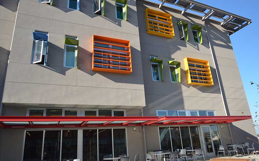
Photo courtesy of Airolite
Sun control features on facades can provide visual interest as well as enhance the energy performance of a building.
Building Expansion Joints
The facades on larger buildings typically require intentional expansion joints (gaps) in the structure to allow for the movement of different parts of the building. That movement can be due to thermal expansion and contraction, seismic loads, or other conditions. However, a gap like this creates a problem for the continuity of the thermal, moisture, and air barriers in a facade. Therefore, specifying and installing the most appropriate type of expansion joint filler is important to be sure it functions properly without compromising any of these barriers. In particular, there is a need to keep bulk water (from weather) and airborne moisture from seeping into or penetrating through the joints and into the facade and/or building. If the wall carries a fire rating, then the expansion joint may need to also carry the same fire rating to be code compliant.
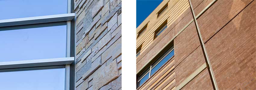
Photo courtesy of Inpro
Expansion joints are often needed in building facades but they can be readily incorporated to blend with adjacent materials.
The appearance of expansion joints may also be a design consideration. In some cases, the fillers can be selected with textures and colors that blend into the appearance of the facade design or create noticeable and intentional lines on the facade. Alternatively, some expansion joint systems are designed to be used with a cover that is made from metal or other durable material that can be integrated into an overall facade design. Some covers allow for the insertion of materials that match the cladding, so the expansion joint completely blends into the facade or other surfaces.
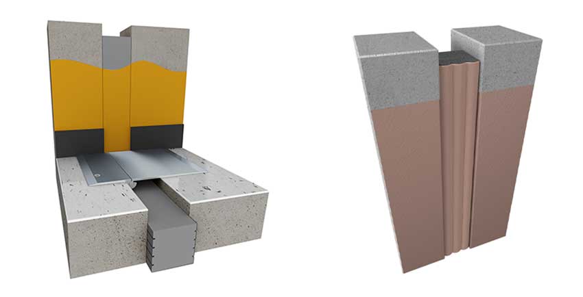
Photo courtesy of Inpro
There are different types of expansion joint systems but in building envelopes, they all need to be resistant to water penetration and maintain other properties as well.
The key to creating successful expansion joints is fundamentally based on understanding the attributes of the different materials or types of system that are available. Effective choices include the use of manufactured foam seals, infilled “pan” systems, and metal cover systems. We will look at some of the choices below and comment on their suitability for different facade applications.
Open Cell and Closed Cell Foams
Open cell foams are available that allow for flow-through of water and vapor. In many exterior veneer systems, if moisture becomes trapped in a wall cavity, building systems allow the moisture to wick out. This is a good quality and a major focus to eliminate potential mold issues in vertical applications.
Closed cell foams, on the other hand, are absolutely watertight and do not allow the moisture to enter the body of the foam. This is the best application for horizontal runs where water could pool or vertical surfaces subject to extreme weather. These are tougher to compress but they expand quite well.
Laminated Foam Layers
Closed cell foams, on the other hand, are absolutely watertight and do not allow the moisture to enter the body of the foam. This is the best application for horizontal runs where water could pool or vertical surfaces subject to extreme weather. These are tougher to compress but they expand quite well.
Layered foam seals are produced using sections of foam that are laminated together. While this is a cheaper manufacturing process, it can result in a product with reduced lifespan due to the vulnerability of delamination of the various layers from each other and its susceptibility to splitting from shear movement. Architects should look closely at the seal’s construction and ask questions of the manufacturer as to the seal’s make-up.
Given batch-to-batch variations in manufacturing, the multiple layers of foam can have different qualities and can expand/compress at differing rates. They may not equalize resulting in inconsistent expansion and “bloating.”
Monolithic Pour Foam Seals
While in a compressed state, all foams look the same, specifications calling for foam seals made with “monolithic manufacturing methods” will avoid product failures and claims down the road.
These seals are produced in a single pour of the foam material to create a monolithic seal. That means there are no layers to delaminate. Batch-to-batch variations inherent in layered foam seals are also avoided by using monolithic pour foam seals.
A good rule of thumb and good practice for foam seals in general is to limit their application with a joint width of no more than 8 inches (200 mm) or smaller. Use of foams for expansion joints larger than 8 inches leads to two things. First, it will exceed the foam’s performance characteristics, and the weight of “super-wide” foam seals can lead to sagging in vertical applications. Second, there are exponentially higher costs in these larger foam seals compared to other expansion joint cover solutions.
Compression Seals
As their name implies, compression seal joint systems are installed into a blocked out joint area and absorb movement through compression and expansion of the pleats in the seal. The rubber-looking, corrugated joint material is also an excellent option for exterior applications where waterproofing is required. Proper use of two-part epoxies ensures solid adhesion, and heat-welded seams ensure watertight performance. The nominal joint width for these systems should not exceed 3 1/2 – 4 3/8 inches (89-111 mm) since the material can’t really handle wider applications than that. Since these are often left exposed, building facade aesthetics can be enhanced using colored compression seals.
Vapor and Thermal Control
Regardless of the type of expansion joint filler system that is used, facades need to retain control of vapor and thermal transfer. For vapor or moisture control, one solution that can be used is to employ a reinforced vapor barrier (RVB) to prevent water infiltration or to channel water to drain locations via an integrated drain tube. Most designers consider the RVB as the go-to-standard for exterior wall expansion joint since they are a durable membrane that resides within the joint. They accommodate movement, but also prevent the penetration of air, debris, and pests from entering through the joint. The critical factor in installation of an RVB expansion joint system is to apply a bed of manufacturer-approved butyl sealant in the concrete block-out area or along the frame along the entire length of the expansion joint. This will aid in securing the moisture barrier to the concrete block-out and provide a watertight seal to prevent seepage around the perimeter of the joint. In order to work properly, always leave enough drape in the moisture barrier to ensure the system will be able to fully open to its maximum distance without interference from the expansion cover components.
Thermal performance in expansion joints is often overlooked in building design, but is no less important than air and moisture performance. There is some minor insulating benefit from RVB joint systems, but an Insulated Vapor Barrier (IVB) system should be considered wherever thermal performance is important. The addition of insulation within the dual-walled vapor barrier provides a higher R Value─and the benefit, of course, is that the R Value works in both directions. Heat or cold don’t penetrate the joint, and interior occupant comfort and HVAC performance are better shielded from the outside conditions along the entire length of the joint. IVBs are also capable of providing up to 50 percent movement, making them a seismic capable system. They are suitable for use in expansion gap sizes ranging from 6 to 28 inches.
Tying in to Work of Other Trades
Expansion joints don’t exist by themselves; they must be tied in to adjacent construction systems installed by other trades. Besides concrete, this can include wood framing, steel decking, steel studs and joists, exterior finish systems, masonry, and even glazing systems. The challenge—and frankly, a potential failure point—is the reliance on the skilled craftsmen and women to tie their particular installation into adjacent materials and systems well. For instance, if the glazing specification and bid documents allow the glazing contractor to simply install the frame and glass and don’t demand tie-in to, say, an adjacent waterproof vertical expansion joint, it invites problems. The same thing works the other way too—if a waterproofing contractor installs the expansion joint system and doesn’t tie into the window glazing, then the seal is not complete.
Conclusion
It is entirely possible to create building facades with more design flexibility and better performance than ever before. Opaque areas can be clad using innovative systems and glazed areas can benefit from improvements in fenestration systems and architectural glass. Architectural louvers and sunshades help with airflow and sun control. Protecting the integrity of facades can be enhanced by the best selection of expansion joint systems. Overall, architects can achieve the desired performance without sacrificing design intent in building facades by staying up to date on the available materials and systems.
Peter J. Arsenault, FAIA, NCARB, LEED AP is a nationally known architect and a prolific author advancing positive acoustical experiences through better building design. www.pjaarch.com, www.linkedin.com/in/pjaarch