This CE Center article is no longer eligible for receiving credits.
Addressing Water Penetration Around Windows
The National Institute of Building Sciences (NIBS) is a nonprofit, nongovernmental organization that brings together government, the professions, industry, labor, consumer interests, and regulatory agencies to focus on safe, affordable structures for housing, commerce, and industry throughout the United States. One of its well-known programs is the Whole Building Design Guide (WBDG), which is a free Web-based portal providing one-stop access to up-to-date information on a wide range of building topics from a ‘whole buildings’ perspective. Development of the WBDG is a collaborative effort among federal agencies, private sector companies, nonprofit organizations, and educational institutions. As such, it has become a recognized standard for best practices in many aspects of building design and construction and is a resource that all architects should take advantage of (www.wbdg.org).
When it comes to windows and their penetrations in walls, the WBDG first encourages everyone to look at window systems realistically, stating, “When designing interfaces for an off-the-shelf window, you should start with the assumption that window frame corners, glazing seals, and perimeter sealant joints will leak at some point during normal service life.”1 While this might sound a little pessimistic at first, the fact is that windows are subject to a lot of different forms of stress that can, over time, cause them to degrade a little, malfunction, or fail completely. The best defense then is to have a backup system built into the wall assembly that will be there when needed to address the unwanted, but quite possible, penetration of water in or around the window. Flashing is an example of such a backup system.
Moving beyond individual products and materials, the WBDG is ultimately focused on how an assembly works together to maintain a quality installation and avoid construction defects of any type. It points out that in a typical wood-framed wall assembly, conventional siding or cladding is not usually meant to be impervious to water or vapor but instead is intended to shed it away or allow it to escape through weep holes or other means. The exterior sheathing behind the cladding is generally designed to be the resistive barrier that drains water down and out of the wall system to the ground or elsewhere. The plane of the sheathing also needs to provide resistance to air infiltration not only to prevent drafts but to prevent air borne moisture from penetrating into wall assemblies. When the multiple tasks of the sheathing are interrupted by a window opening, the WBDG states, “Careful detailing is required to integrate water/air/vapor barriers with the window frames and maintain their continuity at the window perimeters.”1 The key word here is continuity since the windows are creating the interruption or breach in an otherwise continuous sheathing plane designed to resist water and air. The means to achieving that continuity and avoiding common defects comes down to attention to detail in all typical window conditions.

The Whole Building Design Guide and the IBC point out the need to address window openings as an interruption of the air- and water-barrier properties of the exterior sheathing.
Flashing in Codes and Standards
Building codes also recognize the importance of water/air/vapor barriers and their continuity around interruptions. For example, the 2015 International Building Code (IBC) is very clear about this point in Chapter 14: Exterior Walls, Section 1403.2, which reads, “Weather Protection: Exterior walls shall provide the building with a weather-resistant exterior wall envelope.” The code doesn’t dictate how that weather resistance is designed (that is the role of the architect), but it does require the weather-resistant performance of that wall, specifically with the ability to be water resistant. Further, it goes on to state, “The exterior wall envelope shall include flashing, as described in Section 1405.4.” Turning ahead to that section, we can read, “Flashing shall be installed in such a manner so as to prevent moisture from entering the wall or to redirect that moisture to the exterior. Flashing shall be installed at the perimeters of exterior door and window assemblies, penetrations and terminations of exterior wall assemblies, exterior wall intersections with roofs, chimneys, porches, decks, balconies, and similar projections, and at built-in gutters and similar locations where moisture could enter the wall.” In this instance, there seems to be a direct correlation between the code language and with the findings of the insurance industry on the common problem areas. The code is mandating what the rest of the design and construction community may already have learned: Flashing is required to cover over and around interruptions in the weather-resistant barriers and to redirect water or moisture away from the opening or interruption.
With all of the above in mind, let’s look closer at the typical different conditions around window openings.
Window Head Conditions
The head, or top of the window, is the first place that will receive any water draining from above it. In this case, it is clearly important that this water needs to be diverted around the window rather than be allowed to run down into the window. Equally important, the window head needs to be sealed along the junction or seam between the window and the sheathing to prevent intrusion there. Many windows come with nailing flanges that purport to be “self-flashing;” however, if water drains down behind those flanges for any reason, that claim is neutralized. Investigate thoroughly any such products and see what is really needed to allow for the window head to be properly flashed and protected.
The WBDG looks specifically at conventional window head flashing techniques and suggests using durable metal flashings such as zinc-tin coated-copper or stainless steel. However, other flexible products are also available and should be considered based on product capabilities and particular window installations. Either way, window head flashings need to be sloped to the exterior for drainage and provide an outturned drip edge over the top of the window frame. This type of head flashing should extend several inches beyond the window frame to be sure that water drops to the ground and does not seep back into the window unit. It is also common to provide a 4-inch minimum upturned leg above the window that is counter flashed with a wall waterproofing membrane adhered to the vertical leg of the metal flashing. If head flashing is already built in to the window unit, it needs to meet all of these criteria. It may also need to be counter flashed as well since the sheathing, and not the siding/cladding, is the protective drainage surface. Head flashings will end on the sides at the top of the window jambs and need to be sealed both to the window frame and to the jamb flashings to assure a continuous barrier all around the window. For window openings that do not allow extension of the head flashing beyond the opening (e.g. recessed windows), the suggestion is to use dual sealant joints in lieu of head flashing to capture water and direct it to the jamb flashings.
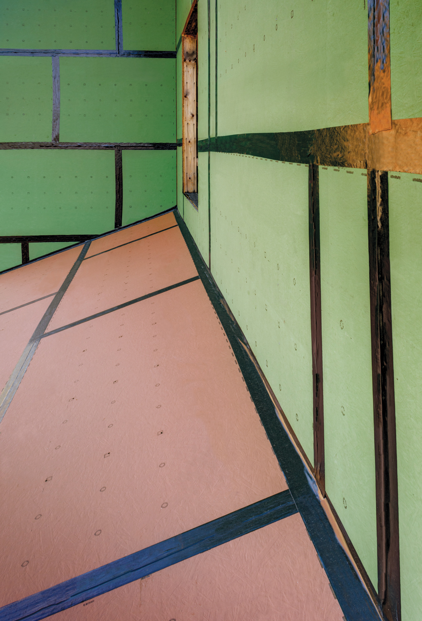
Pictured are the joints of a continuous air and water barrier on the exterior sheathing being sealed.
Window Jamb Conditions
The window jamb, or sides of the window opening, require some specific attention. As suggested in the window head discussion, the junction of the head and jamb is a critical condition since water can seep behind a water-resistive barrier if the window is not sealed properly around its jambs. The WBDG points out that jamb flashings may be metal but more typically are a flexible membrane of a variety of types. The intent is that this jamb flashing extends along not only the face of the sheathing around the window but also the full depth of the framing to catch and redirect any water away from the framing members. Where jamb flashings are part of an air-barrier system, they must be either metal or a membrane that is continuously supported by or adhered to a substrate capable of withstanding changes in air pressures. Otherwise, they will be prone to move and separate from the adjacent surfaces. The WBDG goes on to indicate that membrane flashings that bridge any gaps must be continuous for the full height of the window (i.e., no lap seams) because such gaps don’t allow the support needed to keep seams watertight. When it comes to integrating jamb flashings with wall waterproofing systems, the flashing must overlap the wall barrier and be fully adhered at their intersection to create a continuous connection between the two. Mechanical attachment (i.e., fasteners) of the jamb flashing to the window can be required if there is insufficient surface area on which to adhere the flashing and rely on adhesion alone. Any gaps between the flashing and the window frame must be fully and continuously sealed. Finally, at the base of the jambs, the jamb flashings must be shingled over the sill flashing to properly direct water to run down the jambs and into the sill pan.
Window Sill Conditions
The sill is the base condition of the window that may include a horizontal or sloped surface that is exposed to the weather. If the sill is not designed properly, then rain, snow, ice, or other weather-based water can sit on a sill, seep in behind the window, and find its way into the wall. Since that water will naturally move downward, flashing is needed under the sill to provide an additional layer of protection for the wall below it. Here again, the WBDG makes some recommendations. In cases where the sill flashing is exposed (i.e., not covered by siding or cladding), it suggests using durable metal flashings (e.g., zinc-tin coated-copper or stainless steel) that are sloped to the exterior and provide an outturned drip edge over the face of wall cladding. For the interior condition of such metal flashing, it suggests an upturned leg (1 inch minimum, greater for high-wind exposures) with end dams soldered water tight. Membrane flashings are also appropriate here, where the sill flashings are concealed and drain down into the wall cavity behind the cladding or onto sloped precast concrete or stone sills.
Clearly, each of these window opening conditions (head, jamb, and sill) is important to address and flash properly. There is one additional critical detail to take into account though, namely, the attachment of flashings. If nails or other metal fasteners are used, then those are necessarily penetrating the membranes that are intended to do the protective work of the flashing. Therefore, attachment details need to be coordinated with each other so that attaching one type of flashing does not penetrate another type of flashing, such as a sill detail penetrating the jamb flashing. Further, it is important that fasteners do not penetrate the horizontal portion of sill and head flashings and cause an interruption in the integrity of the flashing. If that is not possible, then those penetrations need to be covered over or counter flashed to assure the integrity of the system.
Water infiltration from outdoors into any building construction is a significant design and construction issue. The reasons are self-evident—unwanted water can cause materials to degrade, contribute to mold growth, and cause damage to people or building contents. While it is common to think of exterior walls and roofs as the primary barriers to water infiltration, the reality is that the technology to create such surfaces that can effectively resist water is readily available and fairly common. The usual problem is the openings in those surfaces, such as roof penetrations or doors and windows that become the weak points in the water tightness of walls. If window or door openings are overlooked or addressed inadequately, then the likelihood of water leaks and the related complications is high. If they are treated properly, through the appropriate use of flashing and integration with adjacent surfaces, then it is much more likely that the successful sealing and protection of walls will be achieved not only in opaque areas, but also in all of the locations where there are openings, too.
All images courtesy of Huber Engineered Woods, LLC © 2016
Windows are typically installed over exterior sheathing in wood-framed walls. Using proper flashing to assure the continuity of air and water barriers along the face of the sheathing is critical to avoiding defects.
Identifying Common Construction Defects
Practical experience and most contractual agreements for design and construction recognize that perfection in buildings is not a realistic goal. Rather, a common “standard of care” is usually identified as a benchmark based on a common understanding of what could be reasonably expected of any competent design or construction professional. Anything that falls below this standard can be considered a defect (or worse, negligence), and many professionals and their insurance companies have spent considerable time and effort determining if, in fact, any defect exists and if so, how to defend against claims for damages.
A white paper published in 2014 by the Travelers Insurance Company (The Travelers Indemnity Company and property casualty affiliates, Hartford, Connecticut) addresses “The continued evolution of construction defect.” While billed as “Strategies for contractors to stay on top of evolving issues” and “Helping companies manage risk,” the paper is very informative for design professionals, too. In this paper, these insurance-company authors identify the following four main types of construction defects.
- Design deficiencies, that is, errors or omissions, can show up in the documents prepared by architects, engineers, or others. If corrections or revisions aren’t picked up during the preparation of the documents, then the deficiency will likely show up afterwards when a building component or system does not work as intended or as expected. As an example, a roof design that didn’t provide proper details to achieve full water tightness but was nonetheless constructed according to the documents and later found to be the source of water intrusion would be determined to be a design deficiency.
- Material deficiencies refers to building materials that are defective or damaged and can subsequently lead to failure despite proper design and construction. As an example, window frames that become bent or warped during shipping to the project site but are nonetheless installed can lead to problems of proper sealing and water resistance. Similarly, inferior products that are substituted for specified products may not function properly or last as long as intended.
- Construction deficiencies usually refers to workmanship that is poor in quality. It could be caused by incomplete work, sloppy, imprecise work, or conversely be very neat and complete, just incorrectly done. This can happen in any trade and in any location in a building with direct implications onto other parts of a building or system that it comes into contact with.
- Operation and maintenance is typically the purview of the building owner or operator. Since some problems emerge only after construction is complete and a project is turned over to its owner, it is important to determine whether a building defect exists or if there is instead a problem with operations and maintenance. After all, at some point, the building passes from being the responsibility of the design and construction team to being the responsibility of those who are operating and maintaining it. For example, some building sealants need regular maintenance or replacement which, if unattended, can cause leaks over time. Those leaks have nothing to do with the design, the construction, or the materials, they simply have everything to do with the realistic service life of the sealant and the fact that maintenance is required.
Recognizing these four types of deficiencies, the next logical question is: Which ones are the most common? The insurance industry has the data in the same paper discussed above to provide that answer. It may come as no surprise that the most common defect causing insurance claims is from water intrusion through the building envelope, either because of a design or construction deficiency. While we might expect such water leaks in roofs, it is also reported to be extremely common around windows, through exterior siding, and around irregular surfaces, such as balconies, patios, and garages. After that, defective materials show up as reasons for insurance claims, including manufacturing defects or premature corrosion or deterioration of things like pipes and other building materials. Finally, and quite significantly, inadequate integration of components or compatibility of materials is a notable issue. Although any of these common conditions can show up on virtually any type or size of building, each individual case can be quite different. That sometimes means that the reason reported for a problem may prove to be something quite different once proper investigation and analysis takes place.
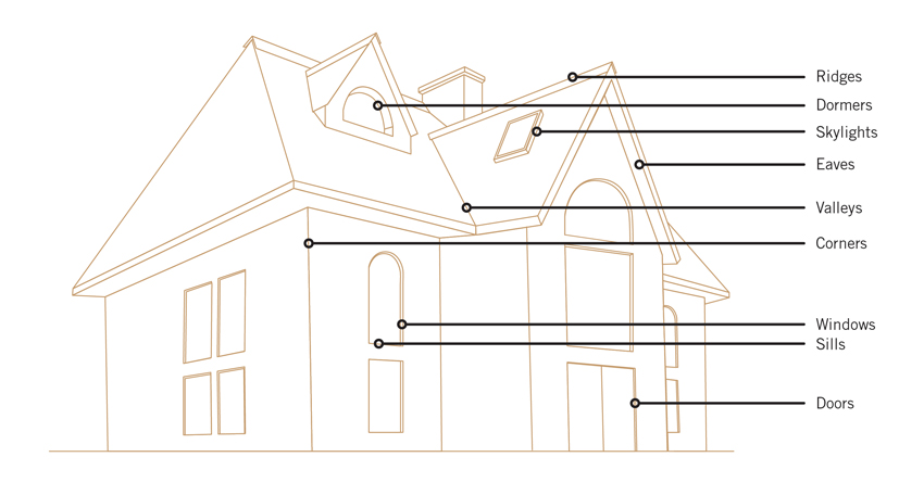
Typically, it is the locations on a building where surfaces or conditions change that can cause construction defects and require flashing to comply with building codes.
Compounding this list of potential issues is the recognized national shortage of skilled trade workers and experienced supervisors, all of whom directly impact on-site quality control. In particular, a 2014 national survey by the Associated General Contractors of America (AGCA) found that 74 percent of firms are having trouble finding qualified trade workers, including carpenters, equipment operators, and laborers. In addition, 53 percent of the firms surveyed report that professional positions, such as project supervisors, estimators, and engineers, are difficult to fill. The implication for this shortage of skilled and experienced workers cuts to the core of quality construction, as quality workmanship requires certain skills. It would be great if a major boost were provided in training people to fill all of these open positions, but realistically, it takes years to develop many of the skills needed in construction and supervision. Recognizing a more immediate need, some product manufacturers have responded by finding ways to simplify installations such that the skills needed to install their products is more focused and requires less time for proficiency. Such quality control that is built into the manufactured systems and installation processes can help to achieve better building results with fewer potential construction deficiencies.
In the end, a proactive approach can be the best defense against all types of construction defects. All design and construction professionals need to keep up with current codes and standards, but staying on top of relevant industry advisories and best practices is also important. Further, actively understanding the capabilities of products being used in any given situation and following manufacturer guidelines will help ensure proper product performance. This can be important in terms of maintaining product warranties and producing a design that performs as intended. Finally, addressing the skills and experience needed for construction professionals engaged in the work will certainly have an impact.
Addressing Water Penetration Around Windows
The National Institute of Building Sciences (NIBS) is a nonprofit, nongovernmental organization that brings together government, the professions, industry, labor, consumer interests, and regulatory agencies to focus on safe, affordable structures for housing, commerce, and industry throughout the United States. One of its well-known programs is the Whole Building Design Guide (WBDG), which is a free Web-based portal providing one-stop access to up-to-date information on a wide range of building topics from a ‘whole buildings’ perspective. Development of the WBDG is a collaborative effort among federal agencies, private sector companies, nonprofit organizations, and educational institutions. As such, it has become a recognized standard for best practices in many aspects of building design and construction and is a resource that all architects should take advantage of (www.wbdg.org).
When it comes to windows and their penetrations in walls, the WBDG first encourages everyone to look at window systems realistically, stating, “When designing interfaces for an off-the-shelf window, you should start with the assumption that window frame corners, glazing seals, and perimeter sealant joints will leak at some point during normal service life.”1 While this might sound a little pessimistic at first, the fact is that windows are subject to a lot of different forms of stress that can, over time, cause them to degrade a little, malfunction, or fail completely. The best defense then is to have a backup system built into the wall assembly that will be there when needed to address the unwanted, but quite possible, penetration of water in or around the window. Flashing is an example of such a backup system.
Moving beyond individual products and materials, the WBDG is ultimately focused on how an assembly works together to maintain a quality installation and avoid construction defects of any type. It points out that in a typical wood-framed wall assembly, conventional siding or cladding is not usually meant to be impervious to water or vapor but instead is intended to shed it away or allow it to escape through weep holes or other means. The exterior sheathing behind the cladding is generally designed to be the resistive barrier that drains water down and out of the wall system to the ground or elsewhere. The plane of the sheathing also needs to provide resistance to air infiltration not only to prevent drafts but to prevent air borne moisture from penetrating into wall assemblies. When the multiple tasks of the sheathing are interrupted by a window opening, the WBDG states, “Careful detailing is required to integrate water/air/vapor barriers with the window frames and maintain their continuity at the window perimeters.”1 The key word here is continuity since the windows are creating the interruption or breach in an otherwise continuous sheathing plane designed to resist water and air. The means to achieving that continuity and avoiding common defects comes down to attention to detail in all typical window conditions.
The Whole Building Design Guide and the IBC point out the need to address window openings as an interruption of the air- and water-barrier properties of the exterior sheathing.
Flashing in Codes and Standards
Building codes also recognize the importance of water/air/vapor barriers and their continuity around interruptions. For example, the 2015 International Building Code (IBC) is very clear about this point in Chapter 14: Exterior Walls, Section 1403.2, which reads, “Weather Protection: Exterior walls shall provide the building with a weather-resistant exterior wall envelope.” The code doesn’t dictate how that weather resistance is designed (that is the role of the architect), but it does require the weather-resistant performance of that wall, specifically with the ability to be water resistant. Further, it goes on to state, “The exterior wall envelope shall include flashing, as described in Section 1405.4.” Turning ahead to that section, we can read, “Flashing shall be installed in such a manner so as to prevent moisture from entering the wall or to redirect that moisture to the exterior. Flashing shall be installed at the perimeters of exterior door and window assemblies, penetrations and terminations of exterior wall assemblies, exterior wall intersections with roofs, chimneys, porches, decks, balconies, and similar projections, and at built-in gutters and similar locations where moisture could enter the wall.” In this instance, there seems to be a direct correlation between the code language and with the findings of the insurance industry on the common problem areas. The code is mandating what the rest of the design and construction community may already have learned: Flashing is required to cover over and around interruptions in the weather-resistant barriers and to redirect water or moisture away from the opening or interruption.
With all of the above in mind, let’s look closer at the typical different conditions around window openings.
Window Head Conditions
The head, or top of the window, is the first place that will receive any water draining from above it. In this case, it is clearly important that this water needs to be diverted around the window rather than be allowed to run down into the window. Equally important, the window head needs to be sealed along the junction or seam between the window and the sheathing to prevent intrusion there. Many windows come with nailing flanges that purport to be “self-flashing;” however, if water drains down behind those flanges for any reason, that claim is neutralized. Investigate thoroughly any such products and see what is really needed to allow for the window head to be properly flashed and protected.
The WBDG looks specifically at conventional window head flashing techniques and suggests using durable metal flashings such as zinc-tin coated-copper or stainless steel. However, other flexible products are also available and should be considered based on product capabilities and particular window installations. Either way, window head flashings need to be sloped to the exterior for drainage and provide an outturned drip edge over the top of the window frame. This type of head flashing should extend several inches beyond the window frame to be sure that water drops to the ground and does not seep back into the window unit. It is also common to provide a 4-inch minimum upturned leg above the window that is counter flashed with a wall waterproofing membrane adhered to the vertical leg of the metal flashing. If head flashing is already built in to the window unit, it needs to meet all of these criteria. It may also need to be counter flashed as well since the sheathing, and not the siding/cladding, is the protective drainage surface. Head flashings will end on the sides at the top of the window jambs and need to be sealed both to the window frame and to the jamb flashings to assure a continuous barrier all around the window. For window openings that do not allow extension of the head flashing beyond the opening (e.g. recessed windows), the suggestion is to use dual sealant joints in lieu of head flashing to capture water and direct it to the jamb flashings.
Pictured are the joints of a continuous air and water barrier on the exterior sheathing being sealed.
Window Jamb Conditions
The window jamb, or sides of the window opening, require some specific attention. As suggested in the window head discussion, the junction of the head and jamb is a critical condition since water can seep behind a water-resistive barrier if the window is not sealed properly around its jambs. The WBDG points out that jamb flashings may be metal but more typically are a flexible membrane of a variety of types. The intent is that this jamb flashing extends along not only the face of the sheathing around the window but also the full depth of the framing to catch and redirect any water away from the framing members. Where jamb flashings are part of an air-barrier system, they must be either metal or a membrane that is continuously supported by or adhered to a substrate capable of withstanding changes in air pressures. Otherwise, they will be prone to move and separate from the adjacent surfaces. The WBDG goes on to indicate that membrane flashings that bridge any gaps must be continuous for the full height of the window (i.e., no lap seams) because such gaps don’t allow the support needed to keep seams watertight. When it comes to integrating jamb flashings with wall waterproofing systems, the flashing must overlap the wall barrier and be fully adhered at their intersection to create a continuous connection between the two. Mechanical attachment (i.e., fasteners) of the jamb flashing to the window can be required if there is insufficient surface area on which to adhere the flashing and rely on adhesion alone. Any gaps between the flashing and the window frame must be fully and continuously sealed. Finally, at the base of the jambs, the jamb flashings must be shingled over the sill flashing to properly direct water to run down the jambs and into the sill pan.
Window Sill Conditions
The sill is the base condition of the window that may include a horizontal or sloped surface that is exposed to the weather. If the sill is not designed properly, then rain, snow, ice, or other weather-based water can sit on a sill, seep in behind the window, and find its way into the wall. Since that water will naturally move downward, flashing is needed under the sill to provide an additional layer of protection for the wall below it. Here again, the WBDG makes some recommendations. In cases where the sill flashing is exposed (i.e., not covered by siding or cladding), it suggests using durable metal flashings (e.g., zinc-tin coated-copper or stainless steel) that are sloped to the exterior and provide an outturned drip edge over the face of wall cladding. For the interior condition of such metal flashing, it suggests an upturned leg (1 inch minimum, greater for high-wind exposures) with end dams soldered water tight. Membrane flashings are also appropriate here, where the sill flashings are concealed and drain down into the wall cavity behind the cladding or onto sloped precast concrete or stone sills.
Clearly, each of these window opening conditions (head, jamb, and sill) is important to address and flash properly. There is one additional critical detail to take into account though, namely, the attachment of flashings. If nails or other metal fasteners are used, then those are necessarily penetrating the membranes that are intended to do the protective work of the flashing. Therefore, attachment details need to be coordinated with each other so that attaching one type of flashing does not penetrate another type of flashing, such as a sill detail penetrating the jamb flashing. Further, it is important that fasteners do not penetrate the horizontal portion of sill and head flashings and cause an interruption in the integrity of the flashing. If that is not possible, then those penetrations need to be covered over or counter flashed to assure the integrity of the system.
Advances in Flashing Solutions
In the spirit of the WBDG and in the interest of mitigating the potential for construction defects, the best flashing solutions need to be looked at holistically in terms of the particular wall construction and the specific windows being used in a project. For purposes of our discussion here, let’s focus on common wood-framed construction as used in single-family and multifamily low-rise residential construction. In this construction type, wood studs are spaced evenly and strengthened with exterior sheathing on the outside and gypsum board applied to the inside. Window openings are framed based on the rough opening dimensions for premanufactured windows and the corresponding openings in the exterior sheathing are cut, thus defining the basic location and conditions for window installations. The actual window units should be specified to prevent leaks through any part of their frame or sash by using sound, proven technologies. These might include mitered corners stiffened by spline inserts, molded corner gaskets, vulcanized perimeter gaskets, and shop-applied perimeter collars as opposed to field-applied sealants. Assuming the window units are good quality and can be expected to perform within an appropriate standard of care, then attention can now turn to the details of continuity of barriers.
Weather and Air Barriers
Before the windows are installed, the requisite barriers need to be accounted for. In northern climates, vapor retarders may be required per the IBC and are typically part of the interior work, which comes later. But since the IBC also requires the weather-resistant barrier on the exterior, such a barrier needs to be installed and coordinated with the window openings. The code identifies two options for a weather-resistant barrier, first indicating: “A minimum of one layer of No. 15 asphalt felt, complying with ASTM D 226 for Type 1 felt” (IBC 1404.2). Asphalt felt has certainly been a traditional material for many wall assemblies; however, it is seen as a rather obsolete material compared to other modern alternatives. Fortunately, the second IBC option is to allow “other approved materials,” which refers to “materials that are acceptable to the building official or authority having jurisdiction” rather than a long list of specific alternatives. Such other approved materials currently include a variety of forms. Some are self-adhered sheet membranes (sometimes called “peel-and-stick” materials) that have commonly been used in roofing applications and were also popular on below-grade walls. There are also spray-on systems that are formulated to be applied in thin or thick applications depending on the product and its makeup. Additionally, there are other types of rolls or sheet goods that have their own requirements for installation. Note that there are a variety of manufacturers and products such that performance can vary considerably based not only on the product but also on the quality control of installing them in the field. Seams and joints are particularly important in this regard and can be a significant source of problems later on if not treated correctly.
An air-infiltration barrier is also required as part of most energy codes along the plane of the exterior sheathing. It is important to realize that not all weather- or water-resistant barriers also qualify as an air barrier and vice versa. It is also notable that in a wood-framed wall with a multitude of individual materials and components, air infiltration can be difficult to control. The key to success lies first in the ability of a particular material to be considered a true air barrier. The codes rely on ASTM E2178: Standard Test Method for Air Permeance of Building Materials as the basis for determination. Hence, any individual material or combination of materials that can demonstrate compliance with this test showing a very limited air permeance can qualify as an air-barrier material. The second key to effectiveness of an air barrier is to look beyond the specific material and to its ability to be truly continuous. That means any joints, seams, penetrations, or other breaches of the barrier need to be addressed in some manner as part of a total system. The codes then look to other specific tests; in this case, namely ASTM E2357: Standard Test Method for Determining Air Leakage of Air Barrier Assemblies and ASTM E1677: Standard Specification for Air Barrier (AB) Material or System for Low-Rise Framed Building Walls.

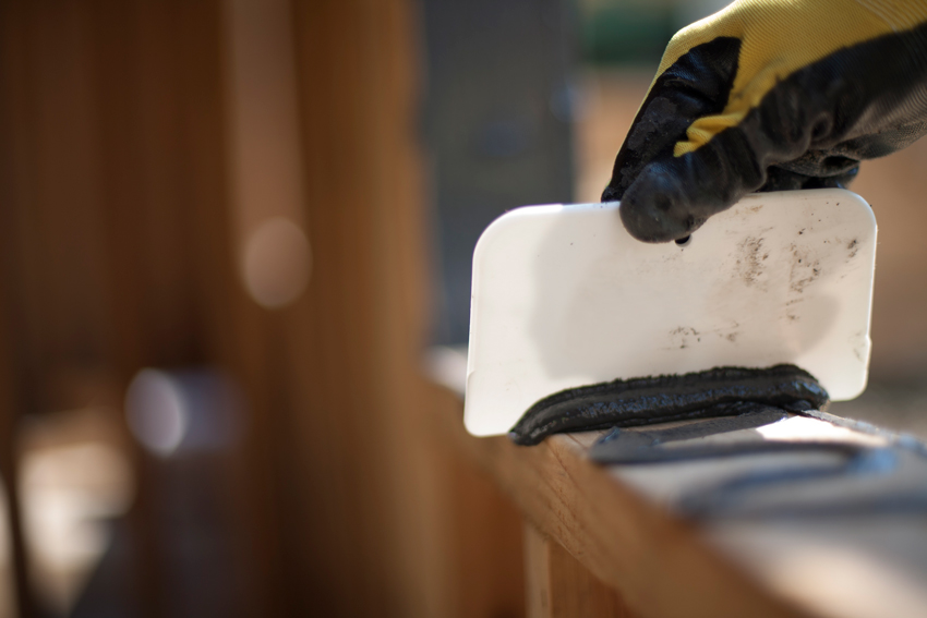
A complete roll-tape system includes everything needed to seal any gaps or seams both in water and air barriers and for flashing installations.
The difference between the testing just for a product (compliance at 4 thousandths of a cubic feet per minute) and the testing for a complete assembly (compliance at 4 hundredths of a cubic foot per minute) might seem to be a big difference, but the net number is still very small. This current code-required level of air infiltration is dramatically less than found in typical wood-framed construction in the past. Its significance lies in the fact that all of the joints, seams, connections, etc. need to be included in the test to be sure that the total assembly does indeed perform as a complete, unbreached air barrier. Commonly, house wrap materials have been popularly used because as a material, they rate very well as an air barrier. Their weakness has been in securing them around penetrations, window openings, and to the sheathing, as well as the sometimes inefficient ability to seal the joints and seams, which can often be seen flapping in the wind prior to the installation of cladding. That has given rise to other systems, such as peel-and-stick or spray-on membranes, which address air infiltration in the full wall assembly and may also carry weather/water-resistant qualities.
Integrated Systems
In designing a wood-framed wall assembly, it is important to be aware of the availability of high-performance, engineered wood sheathings that offer an integrated product approach. Such products provide structural sheathing, a weather-resistant surface, and a qualified air barrier all manufactured into one finished product. This multifunctional approach eliminates the need to identify and install separate products, thus saving steps during installation and lowering labor costs. It also reduces the burden on skilled labor in the field by performing the critical system work under controlled conditions at the factory. Such products address joints and seams by providing advanced adhesive tape systems that have been independently tested and proven to meet the requirements of both a full weather-resistant covering and an air-barrier assembly.2 Part of the beauty of the tape is that it avoids the need for penetrating fasteners, offering a truly continuous seal without fear of compromise from mechanical fasteners.
When it comes to providing flashing that integrates with the air and weather barriers on the sheathing plus addresses all of the needed conditions around windows, there are also some advanced, high-performance products that should be considered.
- Self-adhering, roll-tape flashing products: Traditionally, butyl or asphalt tape has been used successfully in building enclosures, not only for seam covering but for flashing. These have most commonly been used in roofing applications and roof/wall junctures, particularly where other asphalt-based products have been employed. Currently, there are also advanced tapes that are made from an advanced composite acrylic that provides superior adhesion, resistance to ultraviolet (UV) light exposure, and aggressive bonding. Some of these tapes are especially formulated for use with high-performance, multifunction sheathing to assure that they work continuously with the integrated weather and air barriers. One acrylic tape is manufactured to stretch in all directions so that only a single piece is need to flash complex corners and curves that are particularly vulnerable to water leak paths. In this way, the tape flashing can be used to cover the exposed framing and face of the sheathing on heads, jambs, and sills to create a continuous protective layer that seals out water and air around window openings. Such flashing roll tape is available in wider widths than other building tapes to provide the appropriate coverage in a single installation over the full depth and perimeter of window openings, particularly deep window assemblies common in multifamily construction. The fully flashed opening is then ready to receive a window unit, which may then be further counter flashed over or around integral flanges using similar acrylic straight flashing tape. In either case, the tape is pressure rolled into place using hand-held rollers to assure a complete and uniform bonding. This avoids the need for fasteners and does not require any unusual or specialized construction skills to execute.
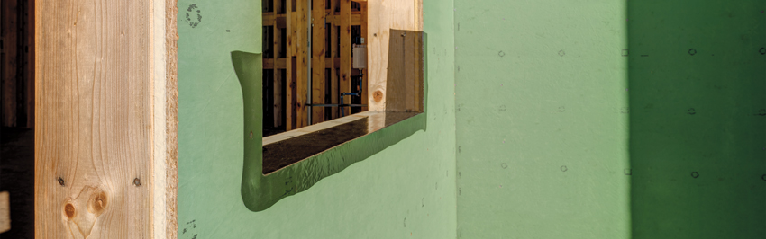
Liquid-applied flashing can be used to seal surfaces completely even in wet or cold conditions.
- Liquid flashing products: Much like other liquid waterproofing products, liquid flashing can be applied for a continuous, seamless condition around windows and other openings. It is common for products like these to be hand applied onto a surface, such as sheathing, framing, metals, etc. Once applied, it is intended to dry to a complete water- and air-proof seal around all portions of a window opening. Since it is usually the thickness of the application that is important to quality control, applicators likely need to be trained in the installation of these flashing products, and on-site quality control becomes very important. Nonetheless, such liquid products are particularly suitable for upper stories in multifamily buildings subject to higher wind ratings.
Part of the effectiveness of liquid flashing is that it can be applied with optimal viscosity to flow easily into irregular shapes and surfaces, such as recessed windows, corners, roof valleys around chimneys, and pipe penetrations. Typically, such flashing can be weather resistant and tack free in as little as 20–40 minutes. Even better, a liquid flashing membrane like this can bond and cure in otherwise unfriendly site conditions, including wet weather and damp substrates. At least one is backed by a 180-day exposure guarantee, meaning that if it remains uncovered for up to six months, it will still perform. In the end, it is usually the architect’s preference whether to use liquid-applied flashings or other systems, but the versatility and durability of these products cannot be ignored, particularly for long-term solutions on larger and taller buildings.
There are a few final considerations when looking at flashing system choices. Ideally, having the ability to use the same flashing system for window openings as for other parts of a wood-framed building, such as wall-to-roof junctions, keeps construction processes simpler by using the same trades and products across a project. This simplicity can make it easier to have effective warranties, too. Choosing to specify an integrated system that provides water and air barriers as well as coordinated flashings can mean that all of these products come from a single manufacturer with a single warranty. That can eliminate any potential arguments over who is responsible if multiple products are used from multiple manufacturers when a problem or defect emerges.
Conclusion
Coordinated flashing systems that integrate with other exterior wall products, such as weather-resistant barriers and air barriers, can prove to simplify installation, reduce the chance for construction defects, and mitigate the professional risk to everyone involved. While there are different material and product choices, the goal is the same for all, namely to create a cost-effective and long-lasting solution for properly and effectively sealing above, below, and around the sides of window and door openings.
End Notes
1Vigener, Nik, PE, and Mark A. Brown. “Building Envelope Design Guide - Windows.” Whole Building Design Guide. National Institute of Building Sciences, 25 June 2012. Web. 10 Nov. 2016. http://www.wbdg.org/design/env_fenestration_win.php. Revised by the Chairs of the Building Enclosure Councils with assistance from Richard Keleher, AIA, CSI, LEED AP and Rob Kistle.
2“ICC-ES Evaluation Report: ESR-1474.” October 2016. ICC Evaluation Service, LLC. Web. 10 Nov. 2016. http://www.icc-es.org/Reports/pdf_files/ESR-1474.pdf.
Peter J. Arsenault, FAIA, NCARB, LEED AP, is an architect and green building consultant who has authored more than 140 continuing education and technical publications as part of a nationwide practice. www.linkedin.com/in/pjaarch

|
ZIP System® products are next-generation exterior wall, roof, and sealing solutions. Innovated to meet today’s design and construction challenges, products including ZIP System sheathing tape, ZIP System™ stretch tape, and ZIP System R-sheathing reduce installation steps and room for error on the job site, while helping to create tight, water-resistant building envelopes. Learn more at InsulateYourBuild.com.
|