The definition of a well-designed building includes the ability to achieve energy performance levels that reduce the need—and associated cost—for purchased energy to operate the building. At a minimum, this means achieving energy performance that complies with energy-conservation code requirements. It can also mean exceeding the minimum code criteria and striving for higher performance as contained in LEED or other voluntary programs. Achieving building designs that meet targeted energy-performance levels can be realized using many different construction methods and building systems. This course looks at one particular construction type that has been successfully used for low-rise commercial buildings for decades, namely metal building systems. While some have erroneously thought that the use of such systems might mean a compromise on energy performance and sustainability, independent research and actual design and construction results clearly indicate otherwise. In reality, working with a metal building manufacturer to design a complete steel structural system with a coordinated set of building enclosure components can meet or exceed high standards of energy performance in a very cost-effective manner.
All images courtesy of Metal Building Manufacturers Association
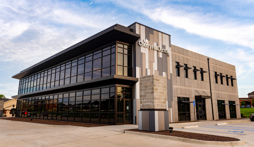
Metal building systems are successfully used to achieve energy performance levels that meet and exceed code requirements while offering great design flexibility.
Metal Building Systems Overview
Metal building systems are offered by manufacturers who generally provide a complete package of products and services for a custom-engineered structure and, when specified, the enclosure as well. Services include in-house structural steel engineering and shop drawings for manufactured products. Based on these drawings, manufacturers can then provide full fabrication of primary and secondary structural steel framing, metal roofing, metal wall cladding, and all accessory and trim components. They may also provide supporting products and materials, such as insulation, fenestration, roof curbs, and roll-up doors. Once the total package is fabricated to order, it is shipped to the project location for on-site erection and installation, typically by an independent erector/installer or general contractor. With this working model as a basis, it is easy to see that it is more streamlined and usually more cost-efficient to design and construct a single-source metal building compared to conventional, multiparty construction.
While some may think that all metal buildings are alike, the reality is that metal buildings take several forms. A total metal building system is one that is a complete package of products and services for a custom-engineered structure. This means it is designed, specified, and built using a primary steel structure (main columns, beams, or rigid frames) with secondary steel components (girts, purlins, etc.) and enclosed with metal wall systems (steel panels) plus metal roof systems or panels. Alternatively, a hybrid building can be created that incorporates only the structural portion, while the wall and roof enclosure is constructed from traditional materials and methods, including concrete, masonry, wood, glazing systems, etc. In other cases, only metal siding or roofing may be added to a conventional or existing building.
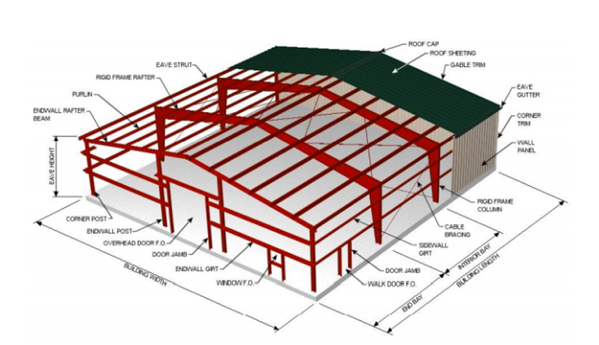
The basic elements of a total metal building system include the primary and secondary steel structure, metal roofing, and metal siding.
The decision to create either a total metal building or a hybrid one rests with the architect and is based on the relevant design criteria of a particular project. The structural aspects are commonly appealing since they offer complete design flexibility with long clear spans capable of creating very open spaces. Total metal building systems offer faster design, streamlined fabrication, and shortened construction process when compared to conventional construction.
Regarding metal siding and roofing, there are two common forms. One is simply the metal panels in a wide range of profiles, colors, and connection options. This approach requires some type of insulation to be added and installed in the wall or roof system behind the metal panels. The other option is to use an insulated metal panel (IMP), which incorporates rigid insulation sandwiched between an inner and outer metal facing to form a composite panel. This type of product is pre-insulated and has appeal in many building applications. It should be noted, however, that most manufacturers will point out that IMPs do not meet the intent of “continuous insulation” because the panel edges intrude within the foam sheathing insulation. However, IMP designs can provide near equivalent insulation values to continuous insulation.
Responsibilities and Roles
Sometimes there is misunderstanding or confusion about who is in control of the parts of a metal building system. In fact, they should be treated no differently than any other building. The architect is still responsible for the design, including defining the code requirements, size, and shape of the building and the related attributes of the form of the building (length, width, height, roof slope, etc.) as part of normal practice. The structural system can be laid out (column spacing, beams, etc.) in concert with input from a structural engineer (provided by either the architect or the metal building manufacturer). The specifics of the exterior also remain under the purview of the architect, including the particulars of the building envelope, such as the insulation, cladding, and any openings (doors, windows).
Using the information contained in the construction documents based on the specifications developed by the design professionals, the building manufacturer can then develop the detailed engineered shop drawings for the building, similar to any other structural shop drawings. The communication path between the architect and the manufacturer is typically through the general contractor, just as with most building projects. Therefore, it is important that all parties are communicating well so that the details of construction are understood and pricing is properly done. It is also important to be clear on which materials and services are being provided by the metal building manufacturer and which are provided under the responsibility of other suppliers or subcontractors, especially for a hybrid building. The architect still needs to specify all of these items, while the general contractor coordinates the different trades and suppliers accordingly.
Understanding the roles of everyone in a project plays directly into meeting the requirements of energy codes. In metal buildings, just like any other building, the architects still need to specify and detail the types and performance criteria of the insulation as well as key requirements for air-infiltration control. Details of minimizing thermal bridging can be coordinated with structural engineers and the manufacturer. The energy efficiency of mechanical and electrical systems will still rest with the design professional designing and specifying these systems. The contractor will still be responsible for the proper field installation of all materials and systems related to energy usage and subject to the normal energy-code inspections.
When using metal building systems for a project, the details of coordinating the metal building components with other materials is still needed. In some cases, the details and processes are the same or similar to traditional building methods. In other cases, there are some specific methods and approaches that have become standardized and streamlined in metal buildings with which designers need to become familiar. These include the way that purlins and girts are typically used in metal buildings, and how this plays into the insulation of walls and roofing. It also includes the recognition that some insulating methods have become common with metal buildings that are not necessarily available or used in traditional building construction. Most metal building manufacturers have detail packages available for download from their website for the architect to reference.
With a basic understanding of the ways that metal building systems are fabricated and delivered, along with a recognition of the options and choices of detailing, we now turn our attention to applying the energy code to this process.
Relevant Energy-Code Provisions
In the United States, there are two common energy codes that are used. The first is prepared and published by the International Code Council and known as the International Energy Conservation Code (IECC). The second is prepared and published by the American Society of Heating, Refrigeration and Air Conditioning Engineers (ASHRAE) and known as ASHRAE Standard 90.1: Energy Standard for Buildings Except Low-Rise Residential Construction. In most U.S. jurisdictions, the IECC has been adopted, but this code also recognizes ASHRAE 90.1 as an “equivalent” document that can be used as an approved alternate to show energy-code compliance. Note that equivalent does not mean identical—there are some specific differences between the two documents. Nonetheless, it has become generally accepted that the resulting energy performance of a building will be essentially the same by following either one. Therefore, the design and construction team needs to decide at the outset which code is being used to show compliance for all aspects of the building (no co-mingling of requirements is allowed—it is one or the other). Some jurisdictions, such as New York City and elsewhere, have made the decision already for all commercial buildings, stating that ASHRAE 90.1 must be used to show compliance. Other jurisdictions have other requirements, including the state of California, which has developed its own Title 24 Energy Code that contains more stringent requirements than either the IECC or ASHRAE 90.1. The design and construction team needs to be clear on what code applies at the location of its building project. Furthermore, since these codes are updated regularly, the team needs to be clear on what version or publication year of the code is required and in use. Providing this information to the metal building manufacturer early in the process is very important.
Despite these different codes, there are some basic provisions and principles that are common to all of them. These principles are based on the fundamentals of physics and engineering related to heat gain and loss, material attributes, and efficiencies of mechanical and electrical equipment. As such, these principles can be applied to any design. The codes then state the minimum threshold of performance in all these areas that must demonstrate code compliance. The same principles can be used to increase a building’s energy performance beyond the code-required minimum to higher levels called for in LEED or other voluntary programs.
Based on the above, following are the first aspects that need to be considered to meet the targeted level of energy performance.

Hybrid metal buildings can take many forms, with coordination, roles, and responsibilities of all involved being the same or similar to other projects.
Scope and Intent
Energy codes do not regulate energy consumption (i.e., fines are not issued if a monthly energy bill is too high), but rather they regulate “design and construction” just like other codes do. The focus here is “effective energy use and conservation” in buildings. The effective energy use part refers to mechanical and electrical equipment that needs to be energy efficient (i.e., controlling the amount of input energy needed to get a desired output, such as light or heat). The energy conservation part (i.e., reduce the need for energy in the building in the first place) is all about the building enclosure, including things like thermal insulation levels, windows, doors, and control of air infiltration (drafts). The energy codes require that these measures need to be effective long-term “over the useful life of the building” just like any other code provisions.
The intent of the energy codes is to focus on conditioned space, meaning building areas that consume energy for heating and cooling. It is important to note that the IECC does not recognize semi-heated buildings (i.e., buildings that are minimally heated but not cooled), a condition that is common in metal building applications such as warehouses and some industrial applications. This is one instance where using the approved alternate, ASHRAE 90.1, is necessary and more appropriate because it does address the semi-heated condition.
Climate Zones
The IECC and ASHRAE 90.1 recognize that different locations have different climate conditions that directly impact a building’s energy use. Therefore, they both identify eight different numbered climate zones: zone 1 in southern Florida progressing up to zone 8 in Alaska. It is important to look up which of these eight climate zones a building is being constructed in because certain energy-code requirements are different based on climate zones. Not understanding this point leads to confusion when the wrong criteria is being followed because the incorrect climate zone is referenced.
Metal building systems are a recognized type of construction in the energy codes with specific prescriptive requirements indicated.
Compliance Path Options
Both the IECC and ASHRAE 90.1 allow the design and construction team to choose one of three methods to demonstrate that the building meets the provisions of the relevant energy code.
- Prescriptive requirement path: This is the most straightforward method but also the least flexible. Here, the codes identify specific construction components, elements, or systems all based on typical construction and state the minimum performance levels of each. In this method, the background calculations have already been done based on standard assumptions about the rest of the construction to achieve a baseline or minimum overall performance level for buildings.
It is important to be aware that there are two forms of prescriptive requirements in the codes, mostly contained in tables that summarize them. The first set is based on R-values that are specifically for the insulation only and not the rest of the assembly. Alternatively, there are U-factor tables that apply to the entire assemblies. These are provided in the codes to allow the designers to use either one. The R-value tables already take into account the assumption of typical construction and set the insulation and other levels accordingly, albeit rather conservatively. If the designer prefers to calculate the U-factors of the total assemblies (i.e., insulation, sheathing, framing, siding, interior finish, etc.) are acceptable and, in some cases, may be more appropriate, particularly if any non-standard construction or unique materials are used. In using the U-factor approach, there are specific criteria that need to be followed and calculations submitted so that the claimed values can be verified by the code-enforcement officer if required. It should be noted that the traditional R-value to U-factor conversion equation, R = 1/U, is not valid regarding the insulation alone. In most instances, the assemblies identified in the U-factor calculations capture the effects of air films, insulation joints and compression, and unavoidable thermal bridges, while the R-value of the insulation alone does not directly include these influences.
- Building envelope trade-off path: The codes recognize that sometimes a particular design or construction assembly may restrict the ability to meet particular prescriptive requirements in the building envelope. Hence, an alternate path allows for a deficiency in one part of the building envelope (i.e., too little wall insulation) to be made up somewhere else in the envelope (i.e., increased roof insulation) to achieve the targeted overall performance. Note that these trade-offs are limited to building envelope provisions only—mechanical and electrical system performance cannot be part of any trade-offs. The most common way to determine if the envelope trade-offs meet the minimum performance level compared to the prescriptive path is to use a free software program called COMcheck. This program has been developed by the U.S. Department of Energy (DOE) and allows designers to pick their location (climate zone) and the particular energy code they are showing compliance with (IECC, ASHRAE 90.1, year, etc.). It then asks for some very straightforward information to be input related to wall assemblies, fenestration, roof assemblies, and foundations. The program executes the calculations and indicates if the design as input passes or fails to meet the selected energy code, and by what percentage of difference. The COMcheck option has been embraced by the design community and code officials, so much that the DOE reports more than 90 percent of the states permit the use of COMcheck for purposes of demonstrating compliance with the adopted code.
- Performance path: There will always be building designs that do not fit neatly into the mold of one of the paths above because of the building owner’s requirements for a more efficient building design, the use of non-standard construction methods, the use of unusual or complex forms, or of restrictions in terms of either the envelope or mechanical and electrical systems being used. The energy codes allow for all of these conditions by offering the alternative of having a complete computer simulation done to calculate the total annual energy performance of the building. In this case, the building design must first be modeled using all of the prescriptive criteria in the code to establish a baseline, comparative performance. Then, a second model is done using all of the proposed differences in the design. Comparing the two needs to show that the proposed design produces the same or better annual energy performance as the prescriptive baseline. The details of what computer programs are acceptable, how to establish the baseline, which items must remain the same, etc. are all clearly spelled out in both the IECC and ASHRAE 90.1. These details are different in each, however, so the correct process needs to be followed, and should be discussed with the code-enforcement officer ahead of time to ensure that everyone is on the same page. Note too that energy models used for LEED submission requirements are defined somewhat differently and will not normally be acceptable for code compliance without some modification to the baseline scenario.
Thermal Bridging
While the IECC and ASHRAE 90.1 have addressed some forms of thermal bridging, not all types of thermal bridges are identified in the codes. Thermal bridges occur when building insulation is interrupted by another building component or material that has a higher rate of conductivity, thus reducing the overall effectiveness of the insulation. A common example is the use of metal stud assemblies that only contain insulation in the cavity space. Heat is transferred directly through the studs, creating a thermal bridge between the inside conditioned space and the outside of the building. As a means to overcome this heat transfer, the prescriptive code requirements call for the use of continuous insulation based on the concept that the continuous insulation will break this transmission path through the assembly. It should be noted that ASHRAE 90.1 is currently developing specific thermal bridging requirements for its future edition of the standard, which will begin to address many other types of thermal bridges.
The energy codes recognize metal buildings as one of several common construction methods. Therefore, in the prescriptive insulation requirements, they acknowledge the different insulation options that are possible (see Table 1). In all of these cases, the intent is to provide insulation that mitigates the thermal bridging effect. For metal buildings, this typically includes holding a layer of insulation outside of the primary and secondary structural members but inside of the metal roof or wall covering. The code does not dictate any particular insulation material, just the performance that needs to be demonstrated. However, to achieve this performance, most manufacturers use a thermal spacer block to isolate the outer siding from the interior framing. These blocks are field installed but function the same way that thermal breaks do in aluminum glazing systems. The size of the thermal spacer block is directly related to the depth of the insulation being used, so it is very important that the architect and designers coordinate these sizes to achieve the intended outcomes. It should be noted that thermal spacer blocks serve a dual function in that they also prevent the compressed insulation beneath from distorting the pan of the standing-seam roof panel. Without these rigid blocks, poor aesthetics and bad modularity of the panels would result.
The principles behind insulating a metal building and overcoming thermal bridging are the same as for any other building: isolate the conductive materials (i.e., steel) from the exterior using a layer of insulation or through different construction techniques. Architects or other design professionals who need to understand the common ways this is done in the metal building sector are advised to access publications available from the Metal Building Manufacturers Association (MBMA) at www.mbma.com. In particular, the MBMA publications titled “Energy Design Guide for Metal Building Systems” and “Energy Code Compliance: A Guide for Metal Building Contractors” provide more detailed information on these topics.
Metal building systems can address thermal bridging and air-infiltration requirements of the energy codes.
Air Infiltration
Many design and construction professionals, and prior versions of the energy codes, typically focused building envelope strategies toward heat transfer as the primary feature to be addressed. This includes insulation levels, amount and size of glazing, heat transfer through fenestration, and similar approaches. In more recent versions of the codes, there are also specific requirements to address the other major aspect of building envelope performance, namely control of air infiltration. This is based on the recognition that a well-insulated building can still perform poorly if unwanted air infiltration (i.e., drafts) is entering or exiting freely and counteracting the gains made in insulation. Since this aspect of energy performance is not easy to calculate in a building design without making some wholesale assumptions, the codes do not rely on computer programs to demonstrate compliance. Instead, there is prescriptive list of mandatory air-infiltration requirements that must be followed regardless of which of the three energy-code compliance paths are followed. Some of these requirements apply to aspects of all buildings (e.g., walls and fenestration), while others apply to specific conditions only when they exist in a building (e.g., loading docks).
The codes offer essentially two alternatives to show that a constructed building meets the air-infiltration requirements. For buildings within certain size ranges, an on-site air-infiltration test can be carried out. This involves following a standard protocol and a “blower door fan” that measures the pressure drop between the inside and the outside of the building when the fan is turned on. A computer processer then calculates the amount of sustained air infiltration at the specified pressure level. If the infiltration rate is too high, remediation measures (e.g., caulking, sealing, etc.) may be needed to bring it into compliance. Note that the codes allow for larger buildings to be segregated into smaller spaces to test and demonstrate compliance. In cases where the blower door test is not practical, the codes require that everything on the prescriptive list is in place and verified to the performance levels stated.
Daylighting
There is another aspect of the energy codes that is sometimes not clear to designers. There is no stand-alone energy-code requirement for daylighting to be used in commercial buildings. Rather, appropriate daylighting can be used to enhance building performance. In particular, the prescriptive requirements of the energy codes are based on a maximum glazed wall area (e.g., 40 percent in the IECC and ASHRAE 90.1). The percentage is for the whole building, not just for a single facade, but if the objective is to have daylight penetrate the interiors of a building floor plan, daylighting may help.
Under the codes, the glazed area can be increased up to an additional 10 percent of wall area, provided the design can demonstrate that clear “daylight zones” are created. These zones are defined for both wall and roof areas and carry some additional requirements. The first is that the glazing does not cause overheating of the building, so projections that shade the glazing and the use of glass that controls solar heat gain are described in the codes. The second is that the daylighting actually decreases energy usage. This means any electric lighting within a daylighting zone needs to have sensors and controls to dim or turn off the lights automatically when there is adequate natural light available.
Proper use of daylighting is a credit option under LEED and can help a building achieve certification. The principles for incorporating daylighting into buildings are essentially the same between the codes and LEED; however, the details are a bit different to show compliance. Therefore, a review of both the relevant energy code and LEED requirements and options is warranted to ensure the proper information and documentation is provided.
With an understanding of how metal buildings are designed, fabricated, and constructed as well as the relevant energy-code provisions, we turn our attention now to the areas of primary architectural significance: how metal building systems can provide high-performance wall and roof assemblies. In so doing, they can be used to comply with the minimum levels of energy performance or specified to achieve higher levels of performance for LEED and other criteria.
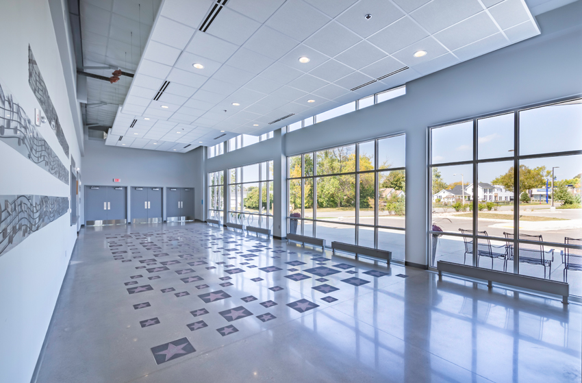
Daylighting can be incorporated into metal building systems in many different ways and coordinated with lighting controls to reduce electrical energy use in buildings.
High-Performance Walls in Metal Buildings
The exterior walls of metal buildings can be designed as part of a total metal building system package or a hybrid construction incorporating some traditional materials and assemblies. Either way, the level of energy performance is under the control of the designer in all of the following areas.
Insulated Opaque Wall Areas
Metal buildings can incorporate any of a multitude of high-performance insulation options, from fiberglass batts to rigid boards or even spray-on insulation. The only types commonly provided by the metal building system manufacturer are fiberglass insulation systems or insulated metal panels. The usual criteria of thickness, R-value per inch, and cost all come in to play when selecting the best insulation for a particular project. The nature of metal building wall systems, however, allows for more options in terms of accommodating the different choices and sometimes can more easily accommodate thicker insulation than standard stud construction for walls, all for a more economical installation.
Using insulated metal walls makes it easy to show code compliance. Since metal building systems are recognized as a typical method of construction, the prescriptive approach is very straightforward to use. This is true whether using the R-value approach of the insulation or the U-factor approach of the entire wall assembly. Since everything is based on known standards and principles, it is easy to show how a particular wall insulation design can exceed code requirements.
Fenestration
Several types and styles of windows and doors are available from metal building manufacturers, but the architect may also specify the fenestration based on commonly used products from other suppliers. These can include windows, storefront systems, or even curtain-wall systems where appropriate. This means that all of the standard and high-performance options for glass, glazing, and frames can be selected from and incorporated into wall facades. As such, the energy performance can be directly controlled to show code compliance or support higher levels of conservation. This wall fenestration can also be used for daylighting by spacing it appropriately along the walls to achieve the desired results. There are no inherent restrictions in fenestration placement by using metal buildings, and in fact there may be fewer compared to conventional construction since long-span structures may require fewer columns to work around in the walls.
Air Infiltration
Since the typical wall assemblies of metal building systems are fairly well known, it is reasonable to test these for air infiltration to determine what would be commonly found in the field. Accordingly, the MBMA conducted a series of tests at the National Association of Home Builders (NAHB) Research Center in 2011 to determine if typical insulated wall systems would meet or exceed the 0.04 cfm/ft2 air-barrier limits for assemblies of materials provided in the IECC and ASHRAE 90.1. The results are summarized in the report titled “MBMA Air Infiltration Testing,” which utilized the ASTM E283 test method at various pressure differentials. The results that are summarized in Table 2 showed that typical metal building walls readily perform better than the energy-code-required air-leakage requirements. Part of this is achieved by the materials themselves (i.e., sheet steel, sheathing, insulation, etc.), and part is from sealing joints and connections using tape, sealant, gaskets, caulk, or other common construction measures.
An additional aspect related to air infiltration is loading docks on buildings. The IECC and ASHRAE 90.1 require the area around loading dock doors to be equipped with weather seals in some climate zones to restrict infiltration when vehicles are parked in the doorway. These seals are attached to the building and allow trucks to back up tightly against them so that air transfer between the enclosed loading dock area and the outside is cut off. This approach has become quite standard for loading docks constructed of all types of materials. Metal buildings are no exception to this and have been used very successfully in many applications.
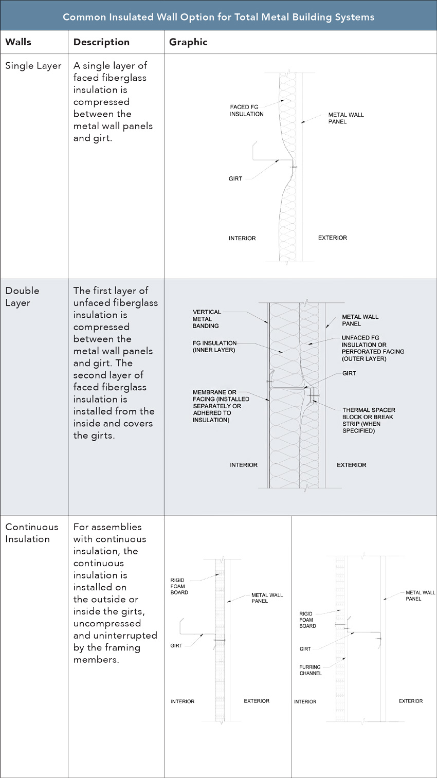
Insulating a metal building walls can be done in a variety of ways both inside and outside of metal wall girts.
High-Performance Roof Systems in Metal Buildings
The basic principles of insulating and air sealing metal roof systems are the same as those for metal wall systems. The full variety of common roof insulation choices remain available, and air-infiltration performance is determined largely by attention to the materials used and sealing the joints between them. Nonetheless, there are some notable aspects of metal roof construction of which to be aware.
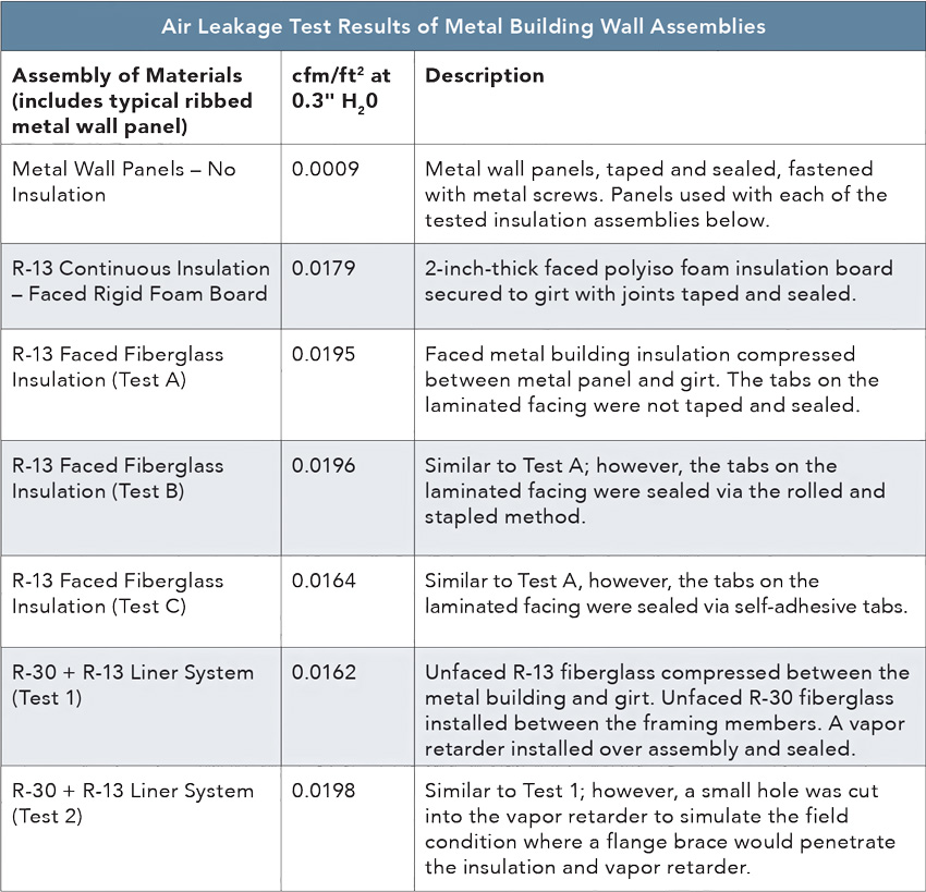
Different metal building wall assemblies were tested for air infiltration according to industry standards and found to be readily code compliant.
Opaque Insulated Roofs
In many low-slope roofing installations (typically those using membrane roofing), rigid continuous insulation is installed entirely above the roof deck and the roofing membrane applied over that. This may be done in metal buildings too, but it is not very common. Instead, the more economical approach of insulating with one or more layers of fiberglass insulation between and above the metal structural members is typically used.
The energy efficiency required as well as the finished look dictates the selection of an insulation system for a metal building. A liner system is made from unfaced fiberglass insulation that is covered with a finish liner material. Filled cavity systems that use a combination of unfaced and faced insulation are also used, while adding continuous insulation to the bottom of the structural members may be appropriate in some cases. The most common system, where it satisfies the energy code requirement, is fiberglass insulation with a vapor barrier facing. All of this is customizable to achieve the desired insulation level in a roof system along with the desired finished look.
Roof Fenestration
Metal buildings can incorporate skylights, clerestories, or other fenestration as may be called for in a particular design. The structure simply needs to be designed to accommodate them, as with any building, and the appropriate product selected to be installed. Since metal buildings are used primarily for low-rise commercial buildings, such roof fenestration can be quite effective in providing daylight and enhancing energy performance. Note that some metal building manufacturers offer roof glazing as part of their product offerings. In many cases, it is a translucent panel that is designed to be substituted for a metal roofing panel. These are popular particularly in large semi-heated buildings like warehouses as a means to provide natural daylight instead of using electrical lights.
Cool Roofs
When solar energy strikes a surface, it can get absorbed and radiate back out as heat. To address this, cool metal roof coatings have been developed that reflect radiant heat, reduce the urban heat island effect, and increase solar reflectivity all to decrease a building’s energy consumption. As such, metal roofing can easily and readily comply with the energy-code requirements that call for cool roofing. Note that there are requirements in the IECC and ASHRAE 90.1, but there are also a number of jurisdictions, particularly in warmer climates, that have imposed higher performance requirements. Information about a particular metal roof’s solar reflectance and thermal emittance can be found through the metal building manufacturer’s product data or on the Cool Roof Rating Council’s (CRRC’s)roof product directory at www.coolroofs.org. Metal roofing is often the best choice to meet and exceed all of these requirements.
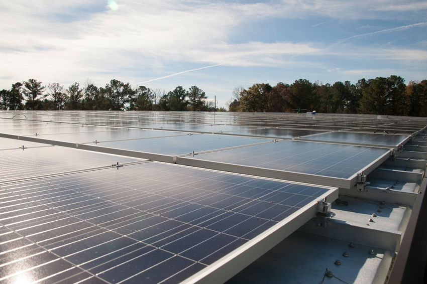
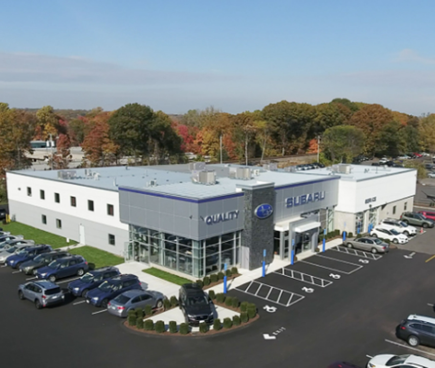
Solar panels can be installed readily onto standing-seam metal roofing, offering a long-lasting, durable solution for generating renewable energy.
Solar Installations
The installation of solar photovoltaic (PV) and solar water systems is not mandated by the codes, but many local jurisdictions have adopted what is referred to as “above-code” or “stretch-code” requirements that mandate solar energy usage. One such initiative is requiring that new buildings be constructed to be “solar ready,” meaning that the building is to be designed and constructed to accept a solar PV or hot water system by virtue of its basic design, orientation, solar access, and detailing. Another initiative is to move toward “net-zero” energy requirements, meaning that the building produces as much energy as it consumes, but using non-polluting renewable energy to do so. Solar PV energy systems are currently the most affordable and practical means to meet these emerging requirements.
Metal building systems are ideally suited to have solar PV systems attached to them. Solar panels are easily installed on standing-seam metal roofing with fasteners that lock directly onto the standing seams and are hidden from view. The clips are especially beneficial because they do not require any penetration of the roof itself, thus avoiding possible water penetration. They also provide an installation advantage since on most other roofing types, a separate racking system is needed that is anchored to the roof by drilling into its surface. Mounting to a standing-seam metal roof is a better option since it eliminates the need for the racking and associated penetrations. Life expectancy is another reason why metal roofs are best suited for solar arrays. The expected service life of a metal roof—recently shown to be 60 years or more—is a better match for the service life of solar panels. The current warranted life of solar panels is 20–25 years, and many of them prove to remain functional well after this time frame. Few commercial roofs, other than metal, will last as long as the solar panels. Hence, if metal roofing is not used, all solar panels will need to be removed and reinstalled each time a roof is replaced, adding time and cost plus potentially causing damage to the system.
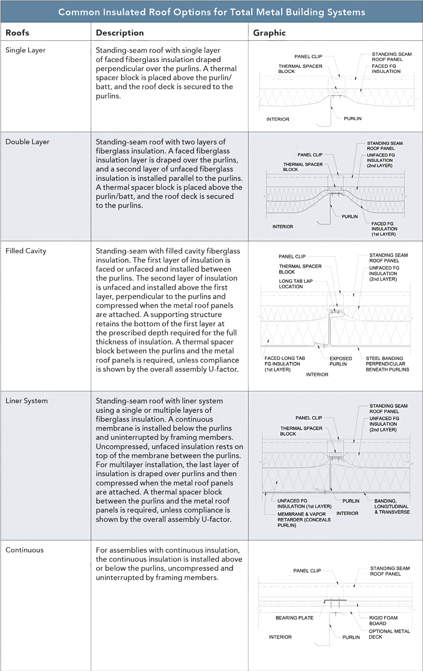
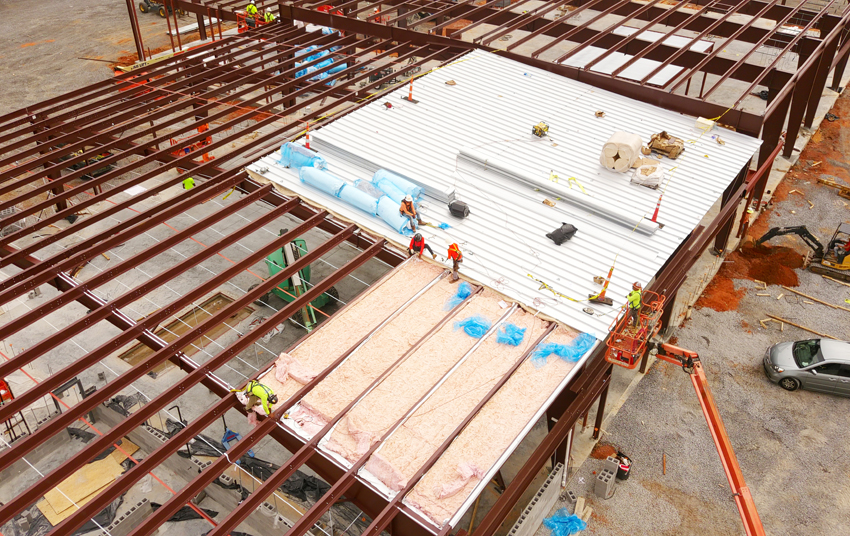
Insulating a metal building roof system can take different forms using a single or multiple layers of insulation to suit energy-code requirements for different climate zones.
Conclusion
Metal building systems have been successfully used for decades by providing a single-source, efficient, economical solution for providing low-rise commercial buildings. Energy codes have been developed that require the design and construction of buildings to be carried out in a manner that addresses energy conservation. Metal buildings have been shown to be very well suited to not only meet the requirements of energy codes but also exceed them. Design professionals can rely on the performance of metal wall and roof systems in particular in regards to energy performance. Additional resources for the design of energy-conscious metal buildings are available from the not-for-profit organization MBMA at www.mbma.com.
Peter J. Arsenault, FAIA, NCARB, LEED AP, is a nationally known architect and prolific author of more than 230 continuing education courses advancing higher building performance through better design. www.pjaarch.com, www.linkedin.com/in/pjaarch