This CE Center article is no longer eligible for receiving credits.
THE POTENTIAL CODE CONFLICTS WITHIN THE BUILDING ENCLOSURE
While the individual requirements for structural support, moisture control, continuous insulation, and NFPA 285 compliance are certainly achievable, the inclusion of so many different elements in an exterior wall assembly creates opportunities for one system to interfere with another and cause the whole assembly to be noncompliant. In common practice, there are four potential conflicts that designers should be aware of in order to maintain the integrity and compliance of the enclosure.
1. Structural Requirements and Moisture Management
Entrapped moisture is problematic in a building enclosure because it can break down the insulation, contribute toward mold and mildew growth, and corrode the steel studs. While the outermost layer of the building, the exterior cladding, is responsible for shedding most of the rainwater, the drainage plane, which exists in the enclosed space between the exterior cladding and the exterior surface of the building structure, is tasked with keeping any water that penetrates the cladding from coming into contact with the physical structure.
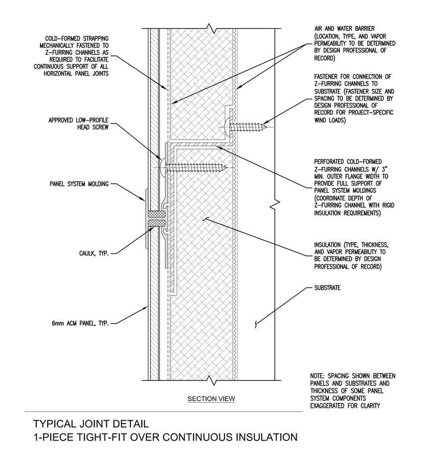
Image courtesy of Laminators Incorporated
This illustrates the use of a perforated cold-formed Z girt to allow for proper and compliant drainage.
In accordance with building codes, the drainage plane of the exterior wall assembly must be designed to allow the water to drain down and out of the building, without interference and without allowing the water access to the structure of the wall. It must also contain the structural supports necessary to hold the veneer in place and sufficiently withstand the weight of the panels and the wind load associated with the location of the building. Unfortunately, placing the elements of the secondary frame into the drainage plane can impact the ability of the drainage plane to manage moisture. The structural supports can create obstacles to the natural egress path of the water as it drains, which could cause a compliance issue. For example, if a structural support within the wall cavity, such as a cold-formed steel Z girt, impedes drainage out of the wall or interferes with airflow impacting the assembly’s ability to dry, there is a potential compliance issue.
Follow a drop of rainwater as it penetrates the exterior cladding and travels into the drainage plane in the wall cavity. The rainwater should be able to flow unhindered down and out of the building. The base flashing should prevent the water from accessing any existing cracks or gaps that would allow it to seep into contact with the building structure. Gravity should allow water to flow over whatever joints or structures may exist in its path. If the water collects anywhere, in any way, such as pooling behind an incorrectly installed structural support, the building enclosure is at risk for the damage that can be caused by entrapped moisture and is not compliant with building codes.
Potential Solutions
There are a number of solutions to allow water a clear path to exit the wall cavity, while simultaneously allowing the secondary framing to support the code-required cladding loads. As mentioned above, Z girts offer a solution that can be installed in a fairly easy and simple manner and are readily available from most building supply companies. Oftentimes, it is economical for contractors to have the Z bent from flat stock. It is important that the detailing of the Z girts be such that it is possible to fasten the Z girt to the wall structure, which typically requires horizontally oriented members. When the members are installed horizontally, there is a greater potential for water flow paths to be blocked at each Z girt. To allow water and air to flow freely within the cavity, it is required to either leave gaps at regular intervals along the length of the Z girts or to specify that the Z girts be perforated along their horizontal leg.
Many proprietary solutions also exist to allow for sufficient structural capacity, while allowing for clear water and air flow paths within the wall cavity. Some systems use discrete brackets to extend the structural supports away from the sheathing by a predetermined distance. The veneer can then be mounted to the structural supports, leaving a fairly open cavity behind for drainage.
2. Structural Requirements and Energy Code/Continuous Insulation
There are many benefits that can be realized from incorporating continuous insulation into a building enclosure, especially when compared to the performance of an exterior wall assembly filled with cavity (batt) insulation. Continuous insulation dramatically improves the thermal performance of the building by minimizing the heat lost through thermal bridging. Thermal bridging occurs when heat flows through the conductive structural supports, often steel or aluminum, that connect the conditioned interior with the exterior. Traveling through the support elements, the heat easily eludes the cavity insulation in a wall or roof enclosure and is lost to the outdoor environment. In a steel-framed building, thermal bridging can reduce the R-value of cavity-insulated wall systems by more than 50 percent. Continuous insulation also reduces the amount of conditioned air that is lost through gaps and cracks in the enclosure because it has fewer gaps and cracks than are found in discontinuous cavity insulation. In addition, continuous insulation often moves the dew point from inside the stud cavity to within the managed exterior wall drainage cavity, which reduces the potential for condensation within the structural portion of the building enclosure.

Photo courtesy of Laminators Incorporated
ASHRAE 90.1 now requires the use of continuous insulation in almost all exterior wall assemblies, and designers are challenged to find ways to attach the exterior cladding to the assembly without breaching the insulation with anything other than screws, bolts, and nails.
There are many different kinds of continuous insulation found on commercial projects. Regardless of whether the particular insulation is a rigid foam product, a spray foam, or stone wool, the most important characteristic of continuous insulation is its continuous and unbroken nature. It is the very feature that gives this layer of insulation its ability to help buildings manage heat so effectively.
ASHRAE 90.1, which now requires the use of continuous insulation in almost all exterior wall assemblies, defines continuous insulation as insulation that is continuous across all structural members, without thermal bridges other than fasteners and service openings. Although the code does not explicitly define the term fasteners, it is generally interpreted as nails, screws, bolts, and items where the thermal transfer is very small. The definition excludes large connection details, such as furring strips, lintels, and clip angles. In practice, this means that a layer of continuous insulation interrupted or breached by a cold-formed steel Z girt is noncompliant and will expose the building to thermal bridging that will dramatically compromise the thermal performance of the enclosure.
The conflict arises because the area in the exterior wall assembly, where designers are tasked with placing a continuous and unbroken layer of insulation, must also host the structural supports that hold the exterior cladding onto the enclosure. Designers are left with a few options for achieving compliance, each with its own advantages and potential issues.
Install Cladding Over Rigid Insulation
One approach to supporting exterior cladding, without breaching the continuous insulation, is to fasten the supports over the top of rigid insulation. In this scenario, the insulation is sandwiched between the sheathing and the furring elements, to which the exterior cladding will attach. This installation method relies upon the long-term stability of the rigid foam layer and the compressive strength of the system. Unfortunately, the rigid foam board can experience some initial crushing that creates inconsistencies or unevenness across the surface and, over time, the foam undergoes a natural creep that further deforms the insulation layer. This instability results in the eventual misalignment of the sheathing, insulation, and furring elements, which compromises the compressive strength of the system. This can result in a substrate that moves out-of-tolerance over the life of the facade, which can be extremely problematic for the exterior cladding it supports and negatively impact the aesthetic of most veneers.
Proprietary Clip and Bracket Systems
An additional caveat to the challenge of incorporating continuous insulation in a building enclosure is that many building claddings are not approved for attachment through more than 1 inch of non-supporting material. In climates where the minimum R-value of the continuous insulation is 7.5, the thickness of the insulation may reach 1½ inches to achieve the requisite R-value.
Proprietary clip systems have been developed that attach exterior cladding to the exterior wall system in a way that is dimensionally stable over time and enables the assembly to accommodate a thicker layer of continuous insulation, if necessary. Unfortunately, these systems may not be viable solutions for projects that require a non-proprietary specification.
Calculate the Wall’s Equivalent R-Value
The ASHARE 90.1 energy code offers multiple compliance paths to provide designers with some much needed flexibility, especially when faced with requirements that conflict with one another. Typically, there is a prescriptive path, which spells out exactly which materials can be used to achieve compliance, and a performance-based path, which enables designers to use different materials or a methodology outside of the prescriptive path, as long as they can demonstrate that the building achieves the desired level of performance. While the prescriptive path tends to be a simpler and more straightforward approach to satisfying thermal performance requirements, because it defines specific continuous insulation requirements, the performance path can offer a means to achieving a compliant design, although it requires a higher level of documentation and more detailed building simulations. As it relates specifically to designing a code-compliant building enclosure, designers can calculate the equivalent thermal values of the exterior wall or hire an energy specialist to provide the calculations.
The exterior wall portion of the building enclosure is a multifunctional part of the built environment. It keeps the majority of exterior environmental loads from getting in, it keeps the majority of building-generated heat from getting out, it is the aesthetic facade, it supports the facade structurally, it manages moisture flow through the exterior wall, and it controls the spread of fire throughout the building envelope; just to name a few of the performance requirements. While building enclosures range from elaborate and cutting edge to basic and cost conscious, every building enclosure must be code compliant.

Photo courtesy of Laminators Incorporated
Exterior wall assemblies must be designed to meet code-required structural support, continuous insulation, moisture management, and fire resistance performance criteria, but available solutions often interfere with one another.
Surprisingly, a code-compliant building enclosure is difficult to design, in large part, because there are conflicts within the building codes that make the path to compliance unclear. This article separates the potential code conflicts into four types:
- Structural Requirements and Moisture Management
- Structural Requirements and Energy Code/Continuous Insulation
- Structural Requirements, Moisture Management, and Energy Code/Continuous Insulation
- Structural Requirements, Moisture Management, Energy Code/Continuous Insulation, and Fire Requirements
While there is no magic bullet, this article will identify potential solutions for these four important conflicts and discuss the advantages and disadvantages of each. Pragmatic application of best practices can help a designer avoid the difficulties associated with these code conflicts and create a functionally compliant enclosure.
BASIC ELEMENTS OF AN EXTERIOR WALL SYSTEM
The exterior wall system is tasked with managing and controlling the movement of heat, air, and moisture into and out of the building enclosure, while providing the requisite structural support for the exterior facade. In order to accomplish this extensive list of interrelated, but diverse, design objectives, the exterior wall assembly includes a number of stand-alone components and systems that must work simultaneously and in close proximity with one another without interfering. A few of the basic components and systems commonly found in an exterior wall assembly include: structural elements, drainage plane (typically the air and water barrier), vapor retarder (optional as required), insulating elements, and exterior cladding.

Image courtesy of Laminators Incorporated
An exterior wall assembly often includes structural elements, a drainage plane, a vapor retarder, insulating elements, and exterior cladding.
Structural Elements
The structural elements inside of the exterior wall system include the structural supports that attach the veneer, or other types of exterior cladding, to the structure. Building codes require that these structural elements be designed to support the self-weight of the veneer and to withstand appropriate environmental loads, such as wind loads. Structural elements include, but are not limited to, the primary wall structure, sheathing, secondary framing system elements (e.g. cold-formed metal furring), and other structural members that are specific to certain proprietary exterior wall systems.
Drainage Plane
The drainage plane in an exterior wall assembly exists to effectively manage moisture but is regularly called upon to manage airflow as well. Most often, the drainage plane is defined with an air and water barrier, an element designed to both manage water and airflow at the same plane within the exterior wall construction. The water barrier is designed to limit exposure of bulk rainwater and condensation to the managed portions of the exterior wall cavity, to enable the exterior wall cavity to dry, and to prevent uncontrolled water from penetrating further into the interior. The air barrier in the exterior wall assembly is intended to control the airflow between the outdoors and the interior, conditioned space. Airflow control is important because airflow carries moisture, spreads smoke, impacts indoor air quality, and influences the movement of heat, which impacts the thermal performance of the building.
Vapor Retarder
Moisture, in any form, needs to be effectively managed in the built environment. While the drainage plane is designed to control the movement of liquid water; water vapor, which refers to water in its gaseous state, is controlled by a vapor retarder. A vapor retarder impedes the flow of water vapor between the exterior assembly and interior walls. The code defines when a vapor retarder is required, and it is oftentimes incorporated into the drainage plane by using a product that can function as a water barrier, an air barrier, and a vapor retarder.
Insulating Elements
The expansion of insulation requirements in the exterior wall system is a relatively new addition to the energy code—the result of a growing demand for improved systems efficiency and increasing interest in satisfying sustainable design initiatives. Insulating elements in the exterior wall system manage the flow of heat in and out of the building. This reduces the heat lost or gained through the exterior wall and improves the overall performance of the HVAC system because less energy is required to keep the building at its preferred temperature.
Exterior Cladding
Exterior cladding refers to the protective layer or finish affixed to the exterior side of the building envelope. The exterior cladding makes an important contribution to the overall aesthetics of the building, but also provides the first layer of protection against bulk rainwater penetration.
There are a variety of materials available to provide exterior cladding that can meet the specific needs of the building and aesthetic preferences of the design team, including different metals and metal composites, stone, wood, and concrete.
THE CODE CHALLENGE
While the variety of functionalities and the different components and systems that must be integrated into the building envelope make for a complex specification, perhaps the most challenging aspect of designing a code-compliant exterior wall system is deciphering the applicable codes themselves. There are many building codes that weigh in on one aspect of the building envelope or another, and they regularly reference other building codes as they describe their prescriptive and alternative compliance paths. When it comes to defining the design requirements of a building enclosure, no single code is self-contained and comprehensive.

Photo courtesy of Laminators Incorporated
Perhaps the most challenging aspect of designing a code-compliant exterior wall system is deciphering the applicable codes themselves.
Intertwined Code Requirements
In order to design a code-compliant building envelope, a designer must satisfy provisions in multiple codes, while navigating the intertwined references and conflicting requirements. Here is a high-level explanation of the current entanglement of the codes defining a safe and acceptable building enclosure.
The International Building Code (IBC) is the model code that defines safe building and design practices, and it has been adopted, in one version or another, throughout the United States. There are many sections of the IBC that apply to the design and functionality of exterior walls. Chapter 14: Exterior Walls establishes minimum requirements for exterior walls in terms of moisture control, fire resistance, and structural support. It defines design and compliance measures for many specific materials used for exterior wall construction. It requires that exterior walls be designed to resist superimposed loads, as required by Chapter 16: Structural Design of the IBC, and meet the fire-resistance ratings, as required by Chapter 7: Fire and Smoke Protection Features of the IBC, if required. Chapter 14 also requires that certain exterior wall assemblies be tested in accordance with and in compliance with the acceptance criteria of the National Fire Protection Association (NFPA) 285 test standard, Standard Fire Test Method for Evaluation of Fire Propagation Characteristics of Exterior Non-Load-Bearing Wall Assemblies Containing Combustible Components (NFPA 285).
In the IBC, Chapter 13: Energy Efficiency requires that buildings be designed and constructed in accordance with the International Energy Conservation Code (IECC). The IECC recognizes the ANSI/ASHRAE/IES Standard 90.1, Energy Standard for Buildings Except for Low-Rise Residential Buildings, as an alternative compliance path. Standard 90.1, section 5.4, outlines mandatory provisions for the thermal performance of the building envelope and requires insulation in the exterior wall system, which improves the overall efficiency of the structure.
Code Requirements for Exterior Walls
As stand-alone mandates, none of the code requirements affecting the design of the building envelope are particularly difficult to achieve. Here is a closer look at the performance requirements as they relate to the necessary structural support, moisture control, thermal performance, and fire resistance that must be included in the specification of an exterior wall assembly.
Structural Support
The IBC requires that the exterior wall assembly be designed and constructed with a structural system that can support the loads imposed upon the exterior cladding or veneer by gravity and wind, without failing or deflecting to a degree that exceeds predefined deflection limits set in Chapter 16. While the gravity load is determined by the weight of the specific material used for the exterior cladding, the IBC mandates that the applicable wind load be determined in accordance with Chapter 6 of the standard written by the American Society of Civil Engineers (ASCE) titled Minimum Design Loads for Buildings and Other Structures, Standard ASCE 7.
Once the appropriate loads have been identified, the support system must be designed. There are many secondary framing options for steel and metal buildings capable of supporting veneer panels. One of the most popular choices are cold-formed steel Z purlins, also called Z girts. The IBC requires that the gravity load imposed by the weight of the exterior cladding and the mounting system must be resisted by the secondary framing. IBC also requires that the design team be able to demonstrate, through rational analysis in accordance with well-established principles of mechanics, the complete transfer path of the wind loads and that the structural system can adequately resist the anticipated loads. Oftentimes, manufacturers will also have tolerance and long-term stability requirements that impose even more stringent design criteria than those required by IBC.
Moisture Control
Uncontrolled moisture in the building enclosure can cause significant damage to the structural integrity of the building and the performance of the building envelope. Factor in its tendency for contributing to mold and mildew production, and it is easy to see why the moisture control measures detailed in the IBC are specific. The IBC requires that exterior walls provide the building with a weather-resistant exterior envelope by incorporating a continuous, water-resistive barrier on the substrate behind the exterior wall veneer. It mandates the use of flashing, a thin layer of waterproof material that controls bulk water at interfaces, and details a number of locations within the building enclosure where flashing must be installed. Ultimately, per the IBC, the exterior wall system must be designed and constructed in a way that prevents water accumulation within the wall cavity, allows for the drainage of any water that enters the assembly, and promotes drying through ventilation.
Continuous Insulation
It has been a trend in the most recent iterations of Standard 90.1 and the IECC to continuously improve upon the energy efficiency and performance of buildings designed to these standards. In ASHRAE 90.1-2007 and IECC 2009, one of the improvements was to require continuous insulation in the exterior wall assemblies of steel-framed, above-grade walls throughout the majority of the United States. Continuous insulation (ci) is insulation that is installed unbroken across all structural members on the exterior side of the wall assembly, without being interrupted by another structure, with the exception of fasteners.
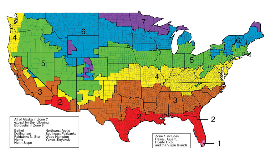
Image courtesy of ASHRAE
ASHRAE 90.1 defines climate-specific R-value minimums for the continuous insulation that must be incorporated into the building envelope.
The effectiveness of any insulation is denoted by its R-value, which measures its resistance to heat flow. The higher the R-value, the more effective a material is at resisting the flow of heat. The codes define prescriptive, climate-specific R-value minimums for the continuous insulation used in the building envelope. For example, in climate zone 3, which includes a wide swath of the Southeast from North Carolina through a significant share of Texas and parts of New Mexico, Arizona, and Southern California, ASHRAE 90.1-2007 requires that steel-framed, nonresidential, above-grade walls incorporate continuous insulation with a minimum R-value of 3.8 into the exterior wall assembly, outside of the primary wall structure.
NFPA 285 Compliance
One of the products commonly used to provide the now requisite layer of continuous insulation in exterior wall assemblies is foam plastic insulation, such as expanded polystyrene (EPS), extruded polystyrene (XPS), and polyisocyanurate (ISO). Unfortunately, foam plastic insulation is most often a petroleum-based product, and when it comes into contact with sufficient heat, it will combust. There are other combustible components that are often included in noncombustible exterior wall assemblies, including: combustible exterior claddings, water-resistive barriers, exterior insulation finishing systems (EIFS), metal composite materials (MCM), fiber-reinforced plastics, and high-pressure laminates. Certain types of combustible wall claddings, MCM for example, require NFPA 285 compliance when the installation is in excess of 40, 50, or 75 feet with multiple, specific requirements documented in the code.
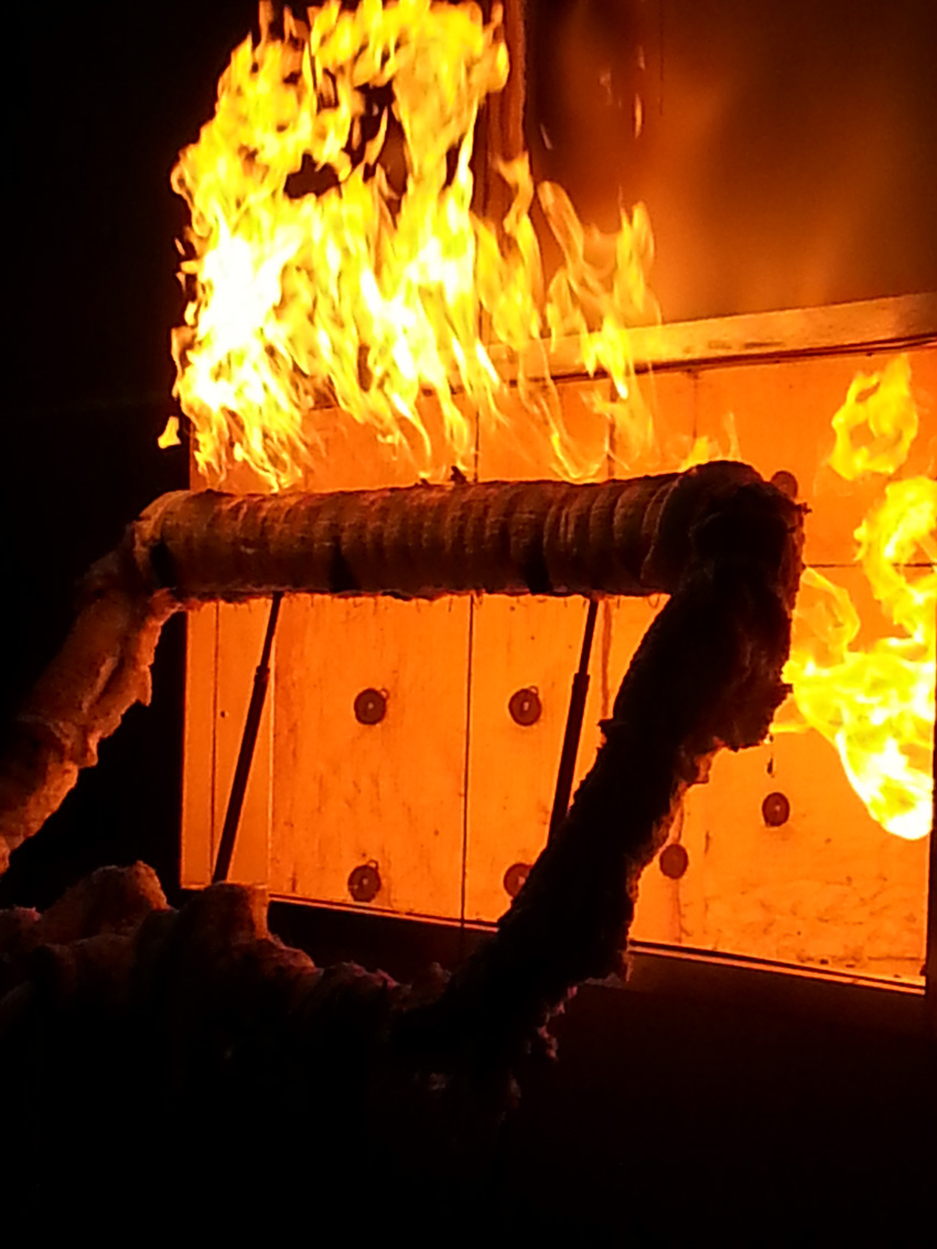
Photo courtesy of Laminators Incorporated
An exterior wall assembly with ACM panels is being tested in accordance with the NFPA 285 test standard.
Although there are exceptions, the IBC requires that most exterior wall assemblies incorporating combustible elements be tested in accordance with, and comply with, the acceptance criteria of the NFPA 285 test standard. The test evaluates the distance that flames travel, vertically and laterally, when the exterior assembly is fully burning and is ultimately designed to determine whether or not an exterior wall assembly burns in a controlled enough manner to give building occupants time to get out of the building safely. Exceptions within the code recognize design scenarios where exterior wall systems are not required to meet the NFPA 285 standard, but they are very specific and should be reviewed thoroughly by the design team if the avoidance of the test standard is an ultimate design objective.
THE POTENTIAL CODE CONFLICTS WITHIN THE BUILDING ENCLOSURE
While the individual requirements for structural support, moisture control, continuous insulation, and NFPA 285 compliance are certainly achievable, the inclusion of so many different elements in an exterior wall assembly creates opportunities for one system to interfere with another and cause the whole assembly to be noncompliant. In common practice, there are four potential conflicts that designers should be aware of in order to maintain the integrity and compliance of the enclosure.
1. Structural Requirements and Moisture Management
Entrapped moisture is problematic in a building enclosure because it can break down the insulation, contribute toward mold and mildew growth, and corrode the steel studs. While the outermost layer of the building, the exterior cladding, is responsible for shedding most of the rainwater, the drainage plane, which exists in the enclosed space between the exterior cladding and the exterior surface of the building structure, is tasked with keeping any water that penetrates the cladding from coming into contact with the physical structure.
Image courtesy of Laminators Incorporated
This illustrates the use of a perforated cold-formed Z girt to allow for proper and compliant drainage.
In accordance with building codes, the drainage plane of the exterior wall assembly must be designed to allow the water to drain down and out of the building, without interference and without allowing the water access to the structure of the wall. It must also contain the structural supports necessary to hold the veneer in place and sufficiently withstand the weight of the panels and the wind load associated with the location of the building. Unfortunately, placing the elements of the secondary frame into the drainage plane can impact the ability of the drainage plane to manage moisture. The structural supports can create obstacles to the natural egress path of the water as it drains, which could cause a compliance issue. For example, if a structural support within the wall cavity, such as a cold-formed steel Z girt, impedes drainage out of the wall or interferes with airflow impacting the assembly’s ability to dry, there is a potential compliance issue.
Follow a drop of rainwater as it penetrates the exterior cladding and travels into the drainage plane in the wall cavity. The rainwater should be able to flow unhindered down and out of the building. The base flashing should prevent the water from accessing any existing cracks or gaps that would allow it to seep into contact with the building structure. Gravity should allow water to flow over whatever joints or structures may exist in its path. If the water collects anywhere, in any way, such as pooling behind an incorrectly installed structural support, the building enclosure is at risk for the damage that can be caused by entrapped moisture and is not compliant with building codes.
Potential Solutions
There are a number of solutions to allow water a clear path to exit the wall cavity, while simultaneously allowing the secondary framing to support the code-required cladding loads. As mentioned above, Z girts offer a solution that can be installed in a fairly easy and simple manner and are readily available from most building supply companies. Oftentimes, it is economical for contractors to have the Z bent from flat stock. It is important that the detailing of the Z girts be such that it is possible to fasten the Z girt to the wall structure, which typically requires horizontally oriented members. When the members are installed horizontally, there is a greater potential for water flow paths to be blocked at each Z girt. To allow water and air to flow freely within the cavity, it is required to either leave gaps at regular intervals along the length of the Z girts or to specify that the Z girts be perforated along their horizontal leg.
Many proprietary solutions also exist to allow for sufficient structural capacity, while allowing for clear water and air flow paths within the wall cavity. Some systems use discrete brackets to extend the structural supports away from the sheathing by a predetermined distance. The veneer can then be mounted to the structural supports, leaving a fairly open cavity behind for drainage.
2. Structural Requirements and Energy Code/Continuous Insulation
There are many benefits that can be realized from incorporating continuous insulation into a building enclosure, especially when compared to the performance of an exterior wall assembly filled with cavity (batt) insulation. Continuous insulation dramatically improves the thermal performance of the building by minimizing the heat lost through thermal bridging. Thermal bridging occurs when heat flows through the conductive structural supports, often steel or aluminum, that connect the conditioned interior with the exterior. Traveling through the support elements, the heat easily eludes the cavity insulation in a wall or roof enclosure and is lost to the outdoor environment. In a steel-framed building, thermal bridging can reduce the R-value of cavity-insulated wall systems by more than 50 percent. Continuous insulation also reduces the amount of conditioned air that is lost through gaps and cracks in the enclosure because it has fewer gaps and cracks than are found in discontinuous cavity insulation. In addition, continuous insulation often moves the dew point from inside the stud cavity to within the managed exterior wall drainage cavity, which reduces the potential for condensation within the structural portion of the building enclosure.
Photo courtesy of Laminators Incorporated
ASHRAE 90.1 now requires the use of continuous insulation in almost all exterior wall assemblies, and designers are challenged to find ways to attach the exterior cladding to the assembly without breaching the insulation with anything other than screws, bolts, and nails.
There are many different kinds of continuous insulation found on commercial projects. Regardless of whether the particular insulation is a rigid foam product, a spray foam, or stone wool, the most important characteristic of continuous insulation is its continuous and unbroken nature. It is the very feature that gives this layer of insulation its ability to help buildings manage heat so effectively.
ASHRAE 90.1, which now requires the use of continuous insulation in almost all exterior wall assemblies, defines continuous insulation as insulation that is continuous across all structural members, without thermal bridges other than fasteners and service openings. Although the code does not explicitly define the term fasteners, it is generally interpreted as nails, screws, bolts, and items where the thermal transfer is very small. The definition excludes large connection details, such as furring strips, lintels, and clip angles. In practice, this means that a layer of continuous insulation interrupted or breached by a cold-formed steel Z girt is noncompliant and will expose the building to thermal bridging that will dramatically compromise the thermal performance of the enclosure.
The conflict arises because the area in the exterior wall assembly, where designers are tasked with placing a continuous and unbroken layer of insulation, must also host the structural supports that hold the exterior cladding onto the enclosure. Designers are left with a few options for achieving compliance, each with its own advantages and potential issues.
Install Cladding Over Rigid Insulation
One approach to supporting exterior cladding, without breaching the continuous insulation, is to fasten the supports over the top of rigid insulation. In this scenario, the insulation is sandwiched between the sheathing and the furring elements, to which the exterior cladding will attach. This installation method relies upon the long-term stability of the rigid foam layer and the compressive strength of the system. Unfortunately, the rigid foam board can experience some initial crushing that creates inconsistencies or unevenness across the surface and, over time, the foam undergoes a natural creep that further deforms the insulation layer. This instability results in the eventual misalignment of the sheathing, insulation, and furring elements, which compromises the compressive strength of the system. This can result in a substrate that moves out-of-tolerance over the life of the facade, which can be extremely problematic for the exterior cladding it supports and negatively impact the aesthetic of most veneers.
Proprietary Clip and Bracket Systems
An additional caveat to the challenge of incorporating continuous insulation in a building enclosure is that many building claddings are not approved for attachment through more than 1 inch of non-supporting material. In climates where the minimum R-value of the continuous insulation is 7.5, the thickness of the insulation may reach 1½ inches to achieve the requisite R-value.
Proprietary clip systems have been developed that attach exterior cladding to the exterior wall system in a way that is dimensionally stable over time and enables the assembly to accommodate a thicker layer of continuous insulation, if necessary. Unfortunately, these systems may not be viable solutions for projects that require a non-proprietary specification.
Calculate the Wall’s Equivalent R-Value
The ASHARE 90.1 energy code offers multiple compliance paths to provide designers with some much needed flexibility, especially when faced with requirements that conflict with one another. Typically, there is a prescriptive path, which spells out exactly which materials can be used to achieve compliance, and a performance-based path, which enables designers to use different materials or a methodology outside of the prescriptive path, as long as they can demonstrate that the building achieves the desired level of performance. While the prescriptive path tends to be a simpler and more straightforward approach to satisfying thermal performance requirements, because it defines specific continuous insulation requirements, the performance path can offer a means to achieving a compliant design, although it requires a higher level of documentation and more detailed building simulations. As it relates specifically to designing a code-compliant building enclosure, designers can calculate the equivalent thermal values of the exterior wall or hire an energy specialist to provide the calculations.
3. Structural Requirements, Moisture Management, and Energy Code/Continuous Insulation
An exterior wall assembly must include structural support for the cladding that effectively manages moisture and enough continuous insulation to meet the requisite thermal performance, as prescribed by the building codes. Unfortunately, the two types of insulation most commonly used in the exterior wall assembly to achieve continuous insulation have their limitations in being able to manage water and adequately resist fire spread.
Stone Wool
Stone wool, also referred to as mineral wool or rockwool, is created by taking a mineral salt and spinning it so that it resembles cotton candy, which is then formed into blankets or boards for use as insulation. Because the matrix is a combination of mineral fibers and air, it resists heat flow efficiently.

Photo courtesy of Laminators Incorporated
This exterior wall system installed stone wool between vertical, cold-formed metal furring, with lumber furring installed horizontally across the face, and is designed to manage moisture behind the stone wool layer.
Unfortunately, because of its constitution, mineral wool has water management issues. It can absorb water, which impedes the exit of moisture from the exterior wall assembly, and exposes the wall cavity to all of the problems that can be caused by trapped moisture. Though it dries with sufficient ventilation, surface tension and capillarity will hold moisture against any surface in direct contact with the stone wool where it has become saturated. In order to design a compliant enclosure with mineral wool insulation, another layer of water control must be added into the assembly. But even this is trickier than it sounds because incorporating multiple vapor retarders and drainage planes into one wall assembly requires careful consideration and detailing.
Rigid Board Foam Plastic Insulation
Foam plastic insulation is available as rigid board in many different chemistries, and each offers a unique balance of cost, efficiency, and capabilities. Some forms of rigid foam insulation do not absorb or retain water and can be used simultaneously as a perfect vapor barrier and the air and water barrier. When detailed properly, it is a good choice for ensuring that the building enclosure allows any water that penetrates the exterior assembly to drain and evaporate out, while simultaneously incorporating continuous insulation. It is important to note that utilizing rigid foam insulation requires careful considerations regarding where the primary water control barrier will be, where the primary vapor control barrier will be, and the treatment of the rigid board joints. If the joints are not properly managed or a type of foam not rated to be an air and water barrier is used, the layer of rigid board insulation can cause moisture to be trapped behind it.
4. Structural Requirements, Moisture Management, Energy Code/Continuous Insulation, and Fire Requirements
As explored in this article, it is possible to achieve a structurally stable substrate with good moisture-managing capabilities and continuous insulation using some combination of a proprietary secondary framing system and rigid board insulation with the drainage plane that has been well-defined and detailed properly. Unfortunately, the introduction of rigid foam insulation into a wall assembly triggers the need to meet the requirements of NFPA 285. Even if rigid foam is not used, NFPA 285 compliance may still be required depending upon the cladding type, the geometry, and the specifics of the installation. Though a very specific combination of systems, materials, and installation methods can achieve the goal of an exterior wall assembly that can rectify all four of the code conflicts, there are very few that can be documented in a manner that demonstrate compliance to the satisfaction of code officials.

Photo courtesy of Laminators Incorporated
Specifying exterior wall systems that are NFPA 285 compliant often requires a proprietary specification that makes it difficult for the project to be competitively bid.
The problem exists because many designers need to keep a specification non-proprietary to encourage competitive bids and a wall assembly that is capable of rectifying the four conflicts is inherently proprietary. The proprietary nature of the NFPA 285 test is a function of the fact that it is an assembly test, not a component test, and it only exacerbates the situation. The NFPA 285 test evaluates the performance of an entire exterior wall assembly when it is fully burning and then deems the entire assembly, built from that specific combination of parts and pieces, as either being compliant or not compliant. Substitutions are not allowed.
In short, it is impossible to write a generic specification for an exterior wall assembly that is NFPA 285 compliant. In order to specify an NFPA 285-compliant assembly, a designer will need to specify an assembly that includes the specific make and model of the exact components that were tested and approved. Any substitution of the insulation, structural support, flashing, cladding, etc. in an assembly requires that it be tested again or, at the very least, will require an engineering judgment letter.
An engineering judgement letter is written by a fire professional or engineer who compares the theoretical performance of a proposed wall assembly to that of an assembly that is NFPA 285 compliant. This professional will incorporate data on the initial NFPA 285-compliant wall assembly and the proposed components to be added and evaluate whether or not the new assembly would be compliant if it were to be tested. Engineering judgement letters are written on a job-by-job basis and only for very specific assemblies. Please note that engineering judgement letters make it possible for designers to specify assemblies that have not yet been tested by NFPA 285 and still satisfy the fire control requirements of the building codes, but they do not make it possible to specify a non-proprietary or generic exterior wall assembly. The acceptance of an engineering judgement letter is at the discretion of the local authority having jurisdiction over the project and the local code official’s willingness to accept the professional’s conclusions.
After reading this article, it may be an understatement to say that specifying a code-compliant exterior wall assembly is complex. It requires that a designer navigate multiple codes and correctly integrate various stand-alone systems in a way that does not compromise the functionality of any individual system or the assembly as a whole. There are a number of potential pitfalls. Structural supports for the veneer of the assembly can impede moisture control or break the continuous insulation. The insulation may require additional air and water barriers or require that the assembly achieve NFPA 285 compliance. To overcome these challenges, it is likely that specifiers will have to collaborate with manufacturers, fire professionals, and local code officials to attain the necessary documentation to demonstrate code compliance.
Jeanette Fitzgerald Pitts has written dozens of continuing education articles for Architectural Record covering a wide range of building products and practices.

|
Laminators Incorporated is a leading manufacturer and provider of aluminum composite panels, installation systems, and support services. Laminators’ lightweight panels are strong, quick to fabricate and install, and available in a multitude of colors, finishes, and installation options to maximize the project design and budget. www.laminatorsinc.com |