This CE Center article is no longer eligible for receiving credits.
The tracks.The track system is built into the truss to guide
the steps. There are actually two tracks: one for the front wheels
of the steps and one for the back wheels of the steps. The relative
positions of these tracks cause the steps to form a staircase as they
move out from under the comb plate. On the inclined portion of
the escalators, the step track is positioned to create a staircase
configuration at the steps. Then, as the steps transition at the top and
bottom of the escalator, the two tracks separate to allow the steps to
"flatten out" at the floor plate.
 |
| Photo courtesy KONE Inc. |
Â
Escalator steps. Most manufacturers offer steps in three
widths: 24-in, 32-in and 40-in wide. The depth of any step tread in
the direction of travel shall not be less than 400mm (15.75in) and
the rise between treads shall not be more than 220mm (8.5in). Most
steps today are fabricated from cast aluminum, which is stronger
and lighter than older escalator step construction.
The handrail. As its name declares, the handrail provides a
convenient handhold for passengers. Manufacturers offer a range of
colors to provide an aesthetic fit.
| Escalator Modernization |
Maintained by the Port Authority of New York and New
Jersey, the George Washington Bridge Bus Station has three
levels?the main concourse with shops and ticket sales, the lower
level with local bus and subway stops and bus platforms on the
upper level. Escalators moving people between each level had
been in service since the station was opened in 1963.
After 40 years of heavy use, equipment malfunctions, lack
of spare parts and addressing safety code changes, escalators
were periodically taken out of service, thereby seriously
inconveniencing the station's 20,000 daily commuters.
Two alternatives were evaluated: rehabilitation and
replacement, reports Port Authority engineers Dharam Pai, PE
and Cheng Chang, PE. Each alternative was problematic. New
replacement parts were hard to obtain and replacing the existing
heavy-duty escalators required significantly more space that
involved structural modifications.
While exploring these options, a third was presented: a
modernization package where an entirely new escalator would
be installed in the existing truss. The package provided a
systematic way of replacing all escalator components with new
custom engineered modular ASME code and New York City
building code compliant components, while avoiding significant
disruptions and construction costs. Two escalators were selected
as a pilot project.
After extensive factory testing (the modernization was
the first for the station's type of escalator) the modules were
attached to the existing truss. Other components were installed in
sequential fashion that followed the procedures of new escalator
construction. No structural modifications were required and no
major rigging, hoisting or crane requirements were necessary
? and no service interruptions.
Cited as a 2007 Project of the Year by Elevator World,
the two modernized escalators offer improved safety, greater
reliability, lower energy use and lower operating costs. Moreover,
the replacement newels, decking and stainless steel balustrades
improve the appearance of the station. |
Â
ESCALATOR DESIGN CONCEPTS
Escalator geometry. Governed by ASME and CSA
(Canadian Standards Association) standards in the U.S. and Canada
(ASME A17.1-2007/CSA B44-07 Safety Code for Elevators and
Escalators), A17.1 requires the angle of inclination for escalators
not to exceed 30 degrees. (Old/historic escalators must conform to
the requirements of ASME A17.3 as a minimum, where adopted by
the local authority.)
This means that for a given floor to floor rise, the work point
(WP) ? the point at which the 30 degree incline intersects with the
floor level ? to work point (WP) dimension is always the same,
regardless of the manufacturer (floor to floor rise x 1.73205.)
Since manufacturers configure escalator components
differently, the distance between the floor level WP and the
point at which the escalator intersects with the building structure
? known as the Face of Support (FOS) ? varies. As a result, all
manufacturers' space requirements between the WP and FOS have
different dimensions.
| Escalator Geometry |
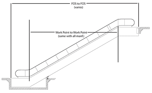 |
Source: KONE Inc. |
Â
Interfacing with the building. The distance between the FOS
at the upper end and the FOS at the lower end formulates the actual
structural opening of the escalator well-way. Then, an 8" pocket
is typically provided at each landing to allow for the alignment of
plate finishes with the walk-on plate.
| Building Interface: Face of Support Details |
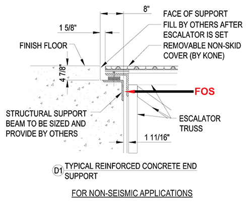 |
Source: KONE Inc. |
Â
The depth and length of the pit, number of level steps and
whether or not intermediate support is required at the back of the
escalator pit will all vary from manufacturer to manufacturer,
depending upon the rise of the escalator and width of the steps.
| Building Interface: Pit Depth, Length
and Intermediate Support Insert |
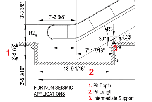 |
Source: KONE Inc. |
Â
U.S. patents for escalators or moving stairways date back to
the mid 19th century, but it was not until the late 1800s that
the world's first operable escalator was installed in Coney
Island, New York and London's Harrods department store. Shortly
thereafter the first commercial model appeared in 1900 and during
the first half of the 20th century manufacturers in both the U.S. and
Europe found a welcome market for their models.
Since then, with improved technology, escalators have routed
people within virtually every building type from hotels to department
stores and transported the public in airports, office buildings and
even outdoors. The world's longest system is the 2,600 ft Central-
Mid-Levels escalator in Hong Kong, which transports tens of
thousands of commuters between their work and residence above
the streets.
Yet escalators do more than efficiently move 90-plus
billion passengers each year. They encourage communication.
Environmental psychologists have noticed that conversations
are broken off at the arrival of the elevator and recommend that
creative corporations specifically request escalators for new offices.
Escalators also offer a unique organizational view that counteracts
the isolation experienced by executives on penthouse floors.
While new construction is the major market for escalators,
renovation and replacement is a growing sector, since an increasing
number of the estimated 50,000 escalators in the U.S. are over 20
years old.
Escalators are not created equally and are unlikely to fit
the same well way. U.S. code requires the angle of inclination
not to exceed 30 degrees and while most manufacturers use similar escalator components, each manufacturer arranges these
components differently.
An understanding of their design concepts and installation
requirements ? and how their functioning varies according to
the kind of project ? is therefore key to designing escalators
for both new and existing buildings. In addition, with the
drive towards sustainable design, awareness of energy efficiencies
and environmental issues in escalator design is becoming
increasingly critical.
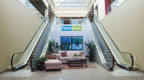
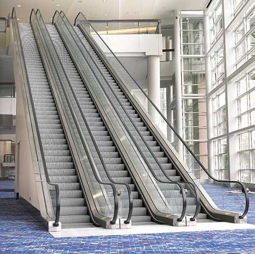 |
Photo courtesy KONE Inc. |
Â
BASIC ESCALATOR COMPONENTS
The essential components of an escalator include:
The structural truss. A truss is the main supporting structure of
the escalator that bridges the lower and upper landings, composed
of two side sections joined together with cross braces across the
bottom and top of the structure. The ends of the truss are attached to
the top and bottom landing platforms via steel or concrete supports.
The truss carries all the straight track sections connecting the upper
and lower modules.
Upper module step and handrail drive system, the main
electrical and mechanical drive, is generally housed beneath thetop
landing platform at the upper end of the unit.
| Escalator Components |
 |
Source: KONE Inc. |
Â
Early technology drive systems used worm gear drives that
were about 70 percent efficient. They used a handrail drive chain/
linkage which, in turn, required high maintenance and messy
oiling. In addition slippage often occurred because of faulty
synchronization.
New technology drive systems are about 94 percent efficient
and employ a planetary gear drive, which eliminates the handrail
drive chain, messy oiling and synchronization problems. The
planetary gear drive uses synthetic-based lubrication and has a
30,000-hour run before the oil needs to be changed, about twice
that of conventional sytems.
Electrical drive systems have improved as well. Full voltage
systems that required high amperage to start have been replaced
with solid state soft-starting controls.
Many manufacturers also offer sensing devices, which monitor
the load on the escalator and adjust motor voltage accordingly.
This can result in electrical cost savings of up to 40 percent over
conventional escalator systems.
The lower modulehouses the step return idler sprockets
or lower reversing station. This lower reversing station component
is now manufactured in cast steel, allowing for a quieter and
smoother transition of the steps and chain around the lower end of
the escalator.
Top and bottom landing platforms.In addition to housing
the upper and lower modules, the top and bottom platforms anchor
the ends of the escalator truss and contain a floor plate, a comb
plate and comb segments. The floor plate provides a place for
the passengers to stand before they step onto the moving stairs.
This plate is flush with the finished floor and is either hinged or
removable to allow easy access to the machinery below. The comb
plate is the piece between the stationary floor plate and the moving
step. The comb segments are mounted to the comb plate and are
so named because their edge resembles the teeth of a comb. These
teeth mesh with matching treads on the top of the steps. This design
is necessary to minimize the gap between the escalator steps and the
comb plate, which helps eliminate entrapments.
Step chain. Each escalator contains two step chains on either
side of the unit. These are basically similar in shape to a bicycle
chain, but much larger, and attach the steps to the mechanical drive
system which continuously pulls the steps.
Historically these chains required constant lubrication,
consuming up to 600 liters of oil in a 10-year period. Further,
they made for an oily mess throughout the interior of the escalator
that required regular clean downs that used strong solvents and
detergents. Most manufacturers now offer a patented lubricationfree
chain as a standard or as an option. These dramatically reduce
oil consumption, eliminate problematic oiling devices, prevent
environmental contamination and significantly cut downtime
associated with housekeeping and maintenance.
The tracks.The track system is built into the truss to guide
the steps. There are actually two tracks: one for the front wheels
of the steps and one for the back wheels of the steps. The relative
positions of these tracks cause the steps to form a staircase as they
move out from under the comb plate. On the inclined portion of
the escalators, the step track is positioned to create a staircase
configuration at the steps. Then, as the steps transition at the top and
bottom of the escalator, the two tracks separate to allow the steps to
"flatten out" at the floor plate.
|
| Photo courtesy KONE Inc. |
Â
Escalator steps. Most manufacturers offer steps in three
widths: 24-in, 32-in and 40-in wide. The depth of any step tread in
the direction of travel shall not be less than 400mm (15.75in) and
the rise between treads shall not be more than 220mm (8.5in). Most
steps today are fabricated from cast aluminum, which is stronger
and lighter than older escalator step construction.
The handrail. As its name declares, the handrail provides a
convenient handhold for passengers. Manufacturers offer a range of
colors to provide an aesthetic fit.
| Escalator Modernization |
Maintained by the Port Authority of New York and New
Jersey, the George Washington Bridge Bus Station has three
levels?the main concourse with shops and ticket sales, the lower
level with local bus and subway stops and bus platforms on the
upper level. Escalators moving people between each level had
been in service since the station was opened in 1963.
After 40 years of heavy use, equipment malfunctions, lack
of spare parts and addressing safety code changes, escalators
were periodically taken out of service, thereby seriously
inconveniencing the station's 20,000 daily commuters.
Two alternatives were evaluated: rehabilitation and
replacement, reports Port Authority engineers Dharam Pai, PE
and Cheng Chang, PE. Each alternative was problematic. New
replacement parts were hard to obtain and replacing the existing
heavy-duty escalators required significantly more space that
involved structural modifications.
While exploring these options, a third was presented: a
modernization package where an entirely new escalator would
be installed in the existing truss. The package provided a
systematic way of replacing all escalator components with new
custom engineered modular ASME code and New York City
building code compliant components, while avoiding significant
disruptions and construction costs. Two escalators were selected
as a pilot project.
After extensive factory testing (the modernization was
the first for the station's type of escalator) the modules were
attached to the existing truss. Other components were installed in
sequential fashion that followed the procedures of new escalator
construction. No structural modifications were required and no
major rigging, hoisting or crane requirements were necessary
? and no service interruptions.
Cited as a 2007 Project of the Year by Elevator World,
the two modernized escalators offer improved safety, greater
reliability, lower energy use and lower operating costs. Moreover,
the replacement newels, decking and stainless steel balustrades
improve the appearance of the station. |
Â
ESCALATOR DESIGN CONCEPTS
Escalator geometry. Governed by ASME and CSA
(Canadian Standards Association) standards in the U.S. and Canada
(ASME A17.1-2007/CSA B44-07 Safety Code for Elevators and
Escalators), A17.1 requires the angle of inclination for escalators
not to exceed 30 degrees. (Old/historic escalators must conform to
the requirements of ASME A17.3 as a minimum, where adopted by
the local authority.)
This means that for a given floor to floor rise, the work point
(WP) ? the point at which the 30 degree incline intersects with the
floor level ? to work point (WP) dimension is always the same,
regardless of the manufacturer (floor to floor rise x 1.73205.)
Since manufacturers configure escalator components
differently, the distance between the floor level WP and the
point at which the escalator intersects with the building structure
? known as the Face of Support (FOS) ? varies. As a result, all
manufacturers' space requirements between the WP and FOS have
different dimensions.
| Escalator Geometry |
|
Source: KONE Inc. |
Â
Interfacing with the building. The distance between the FOS
at the upper end and the FOS at the lower end formulates the actual
structural opening of the escalator well-way. Then, an 8" pocket
is typically provided at each landing to allow for the alignment of
plate finishes with the walk-on plate.
| Building Interface: Face of Support Details |
|
Source: KONE Inc. |
Â
The depth and length of the pit, number of level steps and
whether or not intermediate support is required at the back of the
escalator pit will all vary from manufacturer to manufacturer,
depending upon the rise of the escalator and width of the steps.
| Building Interface: Pit Depth, Length
and Intermediate Support Insert |
|
Source: KONE Inc. |
Â
The width of the escalator pit is typically calculated as
the physical width of the escalator plus two inches to allow
for construction tolerance. Side by side escalators are typically
handled the same way, but the two inches is added only once, not
per escalator.
Code stipulates the width and the length of the landing zone at
each end of the escalator, both of which are driven by the distance
between the centerline of the handrails (CLHR.) This varies with
step width and among manufacturers.
Â
| Code Clearances |
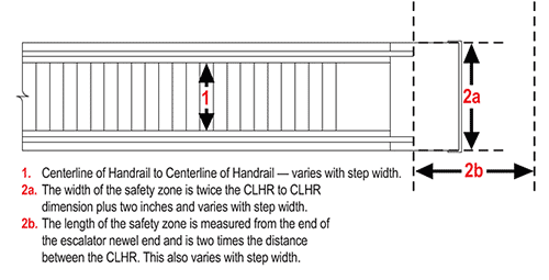 |
Source: KONE Inc. |
Â
Standard escalator features. Most escalator manufacturers
offer the following basic standard features:
Balustrades in "solid" usually #4 or #8 stainless steel and bronze or
glass with thickness either 3/8" or 1/2".
Speed. 100 ft per minute, which is the maximum speed.
Step widths in 24-in, 32-in and 40-in.
Microprocessor based controller.
Maximum travel distance varies with manufacturer.
Painted steps in silver and black
High-impact step inserts in yellow and black
Floor Plate in aluminum and stainless steel
Safety features. (See Safety Features sidebar below.)
ESCALATOR PLANNING
The essential feature of escalator planning is to understand that
there is no one-solution-fits-all. Each project needs to be analyzed
according to its particular requirements.
Applications for Escalators with Different Step Widths |
Size |
Step
Width |
Single-step
capacity |
Applications |
Energy
consumption
in Horsepower |
Small |
24 in |
One passenger |
Two passengers
- one
may walk past
another |
5 HP |
Medium |
32 in |
One passenger
+ one package
or one piece of
luggage |
Two passengers
- one
may walk past
another |
10 HP |
Large |
40 in |
Two passengers
- one
may walk past
another |
Mainstay of metro
systems, larger
airports, train
stations, some
retail usage |
15 HP |
Â
The first place to start is analyzing the market segment. Retail,
office, airport, stadium, hospital or public transit, each require different
features and design aesthetics. Some site-driven features include:
- Type of balustrade. In addition to standard manufacturer offerings
stainless steel, bronze and glass, detailing in brass and ambient
glass are available.
- Step width is specified according to space available and the
requirements of passengers.
- Number of flat steps. Code requires a minimum of two flat steps.
Most commercial projects are designed for two flat steps. Three flat
steps is a common feature found in public transportation projects.
- Weather related features. Water resistant options include galvanized
trusses, water tight control cabinets and electrical switches,
sealed bearings, chain covers, and protective canopies. These are
common in outdoor applications.
- Type of chain. Lubricated chain or lubrication free chain are
options. Depending on the rise, width, and step loading requirements,
chain will be sized accordingly.
- Type of metal finish. 304 type steel is standard. 316 is an available
option for corrosion resistance.
- Type of drive and other components. Planetary gear drives are
standard. Energy saving soft start devices are optional.
Since many of these features can add considerable cost to the
escalator budget, it is important to take time to match the operating
environment with the required features prior to finalizing the project
budget and specification.
| SAFETY FEATURES |
Safety is major concern in escalator design from both the passenger's
perspective and the operational integrity of the escalator system and its
setting. It is important for designers and specifiers to be aware of escalator
installation requirements and available safety features from manufacturers.
Fire protection of an escalator floor opening may be provided by
adding automatic sprinklers or fireproof shutters to the opening, or by
installing the escalator in an enclosed fire-protected hall. To limit the
danger of overheating, adequate ventilation for the spaces that contain the
motors and gears must be provided.
Manufacturers offer some or all of the following as either standard
or optional features:
Operational safety enhancements:
1. Â Control & Annunciator. A microprocessor controller is designed to
work in conjunction with other safety devices to provide correct information
processing and proper escalator control. Escalator faults are identified by
the controller and illuminated in a display on the control cabinet.
2. Â Escalator brake. A permanent magnet ceramic brake is designed
to gradually stop the escalator and hold it stationary under full load.
The closed-loop brake circuit is designed to meet current ASME Code
deceleration rate requirements and operate in conjunction with a velocity
feedback
6. Â Pit stop switch. All escalator machine spaces and areas where
interior access to the escalator is allowed, are furnished with a stop switch.
7. Â Reversal stop device. Protection against accidental or inadvertent
reversing of an escalator operating in the UP direction is monitored by a
directional feedback encoder. This device, when activated, turns off the
motor and activates the brake, bringing the escalator to a smooth stop. This
device is designed to turn off the motor and activate the brake to stop the
escalator when an object is detected entering the handrail inlet area.
9. Â Step up thrust device is designed to detect obstructions in the
lower curve area, which could cause a step to be elevated, thus impacting
the comb plate. When this device detects a raised step, it will shut off the
motor and activate the brake to stop the escalator.
10. Â Handrail speed monitoring device is designed to measure the
variation in speed between the step band and handrail. If speed variation
exceeds the standard, the controller will sound an alarm buzzer, turn off
power to the motor and activate the brake to stop the escalator.
11. Missing step device is designed to detect a missing step. When a
missing step is detected, power to the motor is turned off and the brake is
activated to stop the escalator.
12. Â Step level device is designed to detect a step that is about to enter
the comb area at a "lower elevation" than the comb plate. If a "low step"
is detected, the escalator is turned off and the brake is applied to stop the
escalator.
13. Â Handrail entry device is designed to turn off the motor and
activate the brake to stop the escalator when an object is detected entering
the handrail inlet area.
14. Â Comb impact device is designed to shut off the motor and activate
the brake in the event that comb plate movement is detected horizontally
or vertically.
16. Â Skirt obstruction switch is designed to detect obstructions
between the skirt and step at the point where the step approaches the upper
and/or lower comb plate area. This device will shut down the escalator in
the case of an entrapment.
17. Â Broken step chain device. Installed on the lower end carriage, this
device is designed to detect step-chain breakage or excessive step-chain sag.
Safety Features |
 |
Typical safety features address both operational safety and passenger
safety configurations.
Source: KONE Inc. |
|
18. Â Energy saving control is designed to save up to 40% in energy
costs, extend motor life and provide a smooth, safe start.
Passenger safety features:
3. Â Skirt gap and stiffener. Installation of skirt stiffening channels
is designed to provide uniform clearance between the step edge and skirt,
reducing the possibility of entrapment between the step and skirt.
4. Â Demarcation inserts. Installation of plastic demarcation inserts
along the side and rear of step warn passengers of possible foot entrapment
points and will not wear off after time like paint.
5. Â Emergency stop buttons and alarm. The emergency stop button
installed at a 45 degree angle increases accessibility in the event of an
emergency.
8. Â Step demarcation lights. Green fluorescent light fixtures beneath
the steps at the landings are designed to signal the passenger that the end of
the escalator is near.
15. Â Safety signs. These signs are designed to caution and provide
safety information to the passengers.
19. Â Skirt brushes. These escalator skirt deflector brushes are designed
to encourage safe escalator use by providing a subtle indicator to passengers
riding near the step's edge.
20. Â Deck guards. These plastic barriers are designed to prevent an
object and people from getting wedged between the escalator handrail and
a wall or another escalator.
21. Â Yellow comb segments. Yellow comb segments define the end
of a moving escalator step and the stationary aluminum comb plate while
warning passengers to pick up their feet.
Changes in code have made many safety features mandatory. These
are: the escalator brake (2), skirt gap and stiffener (3, emergency stop
alarms (5), step demarcation inserts (4), handrail entry device (13), comb
impact device (14) and skirt obstruction switch (16).
The only items not required by code are #8 and #18.
|
Â
ESCALATOR REPLACEMENT
Industry estimates note that as many as 30,000 of existing escalators
are 20 years old or more and are in need of updating. There
are several reasons why: moving parts wear out over time, decreasing
reliability and life span, changes to safety codes, replacing old
parts with often-unavailable ?new' old parts becomes costly, etc. In
addition, the efficiency, smoothness and reliability of new equipment
set a higher standard so that older escalators appear painfully slow.
Perhaps the most important reason to update is that new
technology has improved efficiency. New motors and drives require
less electrical usage. Most of the starters on units over 15 years old
employ a full voltage Wye Start/Delta Run connection that requires
a higher starting and running amperage. New types of power control
offered as options by manufacturers adjusts the motor power to the
number of riders using the escalator while maintaining normal speed.
Combined with a solid-state soft-start it can reduce electricity use by
a significant amount. A study conducted by Nevada Power prepared
by Paragon Consulting Services found electrical consumption was
reduced by up to 40 percent.
There are two basic full replacement options for owners
and design consultants seeking to update old escalators ? direct
replacement or complete modernization. Again, each project must
be evaluated on its own merits to determine which approach is
appropriate. Different conditions require different solutions.
Replacement: Factors to consider
? Location. Does access for getting the old units out and the new
units in even exist?
? Building occupancy. How will complete replacement impact
traffic flow in the existing building? What will be the cost of doing
business during replacement?
? Work by others. How much general contractor work is required in
order to tear out and remove the existing units?
? Impact to finishes. How will removing existing units, construction
and installing new units impact existing finishes within the
building?
? Other factors to consider. How will additional security, housekeeping,
and so forth, impact the budget and the building occupants?
? All factors must be looked at closely in order to come up with best
overall value to the client.
Replacement: The Process
Since escalators become part of the foundation of a building structure,
removing and replacing them can turn into a much larger
project than first considered. Each stage from prep-work through
wrap-up needs to be quantified.
| Escalator Replacement Modules |
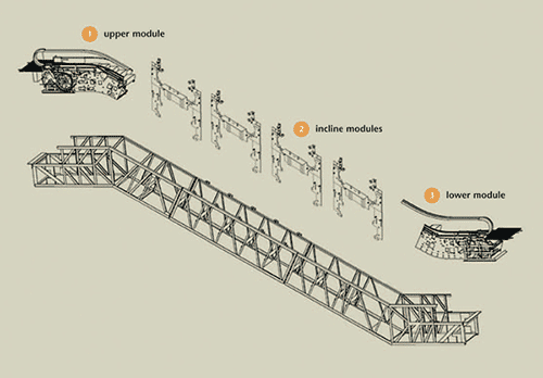 |
Source: KONE Inc. |
Â
Prep-work required before the removal of the existing trusses
includes installing OSHA-approved barricades around the entire
escalator well way; protection of flooring; removal of all existing
escalator cladding; demolition of adjacent finishes; demolition of
adjacent features; installation of scaffolding.
Removal includes the removal of sprinklers and water lines, all
electrical wiring, ventilation and ducts; and the concrete and tile
surrounding the escalator access covers.
The major work is the demolition and removal of existing structural
steel escalator truss, usually at overtime rates. The truss typically
needs to be laid down flat and cut into pieces for removal from the
building. In many cases, the existing pits need to be torn out and
replaced since new escalators will require a different well-way size
from the existing ones. Sprinklers and water lines may also need to
be removed and re-installed.
Installation. New escalator trusses are brought into the building in
pieces, married together on the floor and then hoisted into the newly
constructed well ways.
Wrap-up. All finishes and features torn out in order to allow access
for the new equipment must then be rebuilt or replaced before the
new escalators can be put into service; the flooring repaired at the
newly reconstructed pit; removal of scaffolding and barricades;
ceramic or carpet replacement.
Builder risk insurance, city impact fees, architect/engineer design
fees add to the cost, as does the additional work by the trades for
replacing fire and sprinkler systems, lighting and HVAC. In many
cases the work of the general contractor and by others can be more
than the cost of the escalators.
Escalator modernization
Modernization, in essence, is removing all of the existing internal
components of the escalator, while keeping the truss, and replacing them with brand new escalator technology. The end result is a
new escalator without the time and expense of all the construction
associated with a full replacement.
Modernization is often far less disruptive to the surrounding
building operations and it is often possible to keep one escalator
running while the other is being modernized.
The modernization process starts with stripping the existing
escalator down to the structural steel truss. No adjoining finishes are
removed or damaged and the need for most of the general contractor
work associated with a full replacement is eliminated.
Modernization installation sequence
? Small barricades are installed around the upper and lower ends of
the escalator. As one of the side by side pair of escalators is being
modernized, a protective barricade is also installed between the
two units.
? All internal components are removed from the old escalator. The
torn out components are recycled when feasible. The truss and all
other attached finishes are reused.
? Upper and lower end modules are set in place and aligned.
? Incline modules are then installed to the existing truss cross
members. Step tracks are also installed throughout the entire
length of the unit.
? Step chain and escalator steps are installed and the unit is put
under a test run.
? Architectural features such as decking and balustrade panels are
installed next.
? Finally, the handrails are installed and the units are cleaned and
turned over for use.
In many cases, Escalator Modernization offers the best value
solution for many customers when all final construction costs and
the level of disruption associated with most replacement projects are
avoided. That being said, a project specific analysis should always
be performed to determine the best solution for each application.
Replacement and Modernization Options |
Replacement Option |
Modernization Option |
Good access to building |
Poor or no access to building |
Good access to building |
Drive up access not possible
Stacked escalators exist |
Minimal general contractor
work required |
Extensive general contractor
work required |
Minimal general contractor
work required |
Keeping units in operation is
required or preferable |
Â
CONCLUSION
Since their introduction a century ago, escalators have become
an efficient means of routing and transporting large numbers of
people in numerous market segments from hotels and airports
to office buildings and public transit. New technology has made
significant improvements in step and handrail drives efficiency and
reduced electricity costs while changes in codes are requiring new safety features. A knowledge of basic design concepts and an
understanding of various component systems is therefore critical.
Given the fact that a large portion of escalators now in service
are 20 years old or more, designers are increasingly required to
make the choice between replacement or modernization. Having the
tools to evaluate and determine which option is most appropriate for
a building will help in selecting the solution, which offers the best
overall value for the client.
Â
|
KONE's objective is to offer the best people flow experience by developing and delivering solutions that enable people to
move smoothly, safely, comfortably and without waiting from one place to another. KONE, a global leader, provides its
customers with industry-leading elevators, escalators and innovative solutions for modernization and maintenance.
www.us.kone.com |
|