This CE Center article is no longer eligible for receiving credits.
Today, two primary baseline building energy codes may be adopted by states and local jurisdictions to regulate the design and construction of new buildings: the International Energy Conservation Code® (IECC) and the ANSI/ASHRAE/IESNA Standard 90.1 Energy Standard for Buildings except Low-Rise Residential Buildings. The IECC addresses all residential and commercial buildings, while ASHRAE standards cover commercial buildings. The IECC adopted, by reference, ASHRAE 90.1; that is, compliance with ASHRAE 90.1 qualifies as compliance with IECC for commercial buildings.
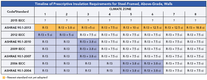
The original standard ASHRAE 90 was published in 1975. In 1999, the standard was placed on continuous maintenance, which allowed it to be updated several times a year due to rapid changes in technology and energy prices. In 2001, the standard became ASHRAE 90.1, and has been updated in 2004, 2007, and 2010, with associated increases in scope and energy-efficiency targets. The 2013 update of ASHRAE Standard 90.1 is a major revision, containing more than 100 changes from the 2010 version. Standard 90.1-2010 and 90.1-2013 together produce almost 50 percent energy savings from the 2004 version.
 |
Click to view large table image
Courtesy of Knight Wall Systems |
Most states apply the standard or equivalent standards for all commercial buildings while others do so for all government buildings. While energy codes are widely considered an efficient way to reduce energy use in the built environment, adoption of standards by states can lag their introduction by a matter of years. ASHRAE 90.1 2007 is the most up-to-date version of the energy code that's been adopted by many jurisdictions and local codes.
One specific and important part of the energy codes currently being implemented calls for an increased performance requirement on exterior wall assemblies, especially with steel-framed walls. The overall goal here is to increase the performance of the wall assembly in resisting the transfer of thermal energy so the conditioned space requires less work by the HVAC system to maintain desirable conditions.
While the code doesn't actually state that exterior insulation is required, it does state that much higher performance numbers must be met. It is widely accepted that the simplest, most expected, and versatile way to increase a wall assembly's thermal performance is by use of insulation applied to the exterior of the wall. Exterior insulation is typically marketed as “continuous insulation” or ci. Ci has been an energy code requirement since the release of ASHRAE 90.1-2004, and the 2007 code calls for more ci in various climate zones. The U.S. Green Building Council's Leadership in Energy and Environmental Design (LEED) rating system has followed suit, increasing its prerequisites in the Energy and Atmosphere category. LEED 2009 requires ci per the 2007 ASHRAE code, and the current version of LEED ups that requirement to conformance with ASHRAE 2010.
ASHRAE 90.1 defines ci as insulation that is continuous across all structural members without thermal bridges other than fasteners and service openings. It is installed on the interior, exterior, or is integral to any opaque surface of the building. Fasteners include screws, bolts, nails, etc, meaning that furring strips, clip angles, lintels, and other large connection details are excluded, rendering standard wall assemblies obsolete and calling for a change in the assembly away from batt-insulated stud cavities. The most recently adopted version of the Washington State energy code, one of the most stringent in the country, has even gone so far as to state the specific amount of cross-sectional area of metal allowed to penetrate the insulation and still qualify as ci.
Why Batt-Insulated Cavities Don’t Work
Batt insulation limits thermal protection to the wall cavity and creates a thermal bridge for heat transfer through framing studs. In a steel-framed building, thermal shorts reduce the R-value of cavity-insulated wall systems by more than 50 percent. In addition, thermal bridging encourages condensation and moisture build-up that can further reduce the R-value of cavity batts as well as encourage mold and mildew and shorten the service life of the entire wall assembly.
Thermal Bridging—The Key to Effective Insulation
Understanding the dynamics of thermal bridging is critical to specifying the right insulation for a given project. Heat energy transfers from warm environments to cold environments, that is, from the interior of a building to the exterior of a building and vice-versa in warm climate zones. Conduction heat transfer is the underlying cause of thermal bridging. The heat energy transfers through connected materials where one part of the connected materials, or assemblies, are in a warm environment and the other end of the connected materials, or assemblies, are in a cold environment; in other words, exterior wall assemblies where one side of the wall is a conditioned space and the other side is an unconditioned space, or outside. The rate at which the heat energy transfers is directly related to the thermal conductivity of the materials connecting, or bridging, the two environments. Metal, for instance, is highly conductive of heat, which is why it is used for activities where conductive heat transfer is important such as cooking food on a stovetop, radiators, etc. The goal is to keep the overall thermal conductivity of the materials bridging the two environments as low as possible, therefore increasing the assembly's ability to resist heat transfer.
 |
|
Image courtesy of Knight Wall Systems |
Adding insulation into an exterior wall assembly is primarily to help increase the resistance to heat transfer through the entire assembly, both inwards and outwards. Bridged materials with a low resistance to heat transfer—and consequently very conductive—which pass through highly resistant materials create a path for heat to follow and “go around.” This is also known as a thermal short, or following the path of least resistance. As an example, metal framing members, such as steel studs, penetrating the insulation added to the assembly, create a bridge and allow heat to transfer right through the insulation at 16 inches on center.
Penetrations are pathways for heat to transfer and are known as thermal bridges. The greater the pathway, the greater the amount of heat energy is lost, creating higher operating costs among other risks. To help reduce this, the assembly design must reduce the amount of conductive material bypassing the insulation, use greater thermally resistant materials within the assembly, and finally break the bridge, or connection, of materials transferring heat energy.
 |
|
Courtesy of Knight Wall Systems |
When a wall's R-value is considered, it is important to realize the assembly's R-value is not the rated R-value of the insulation. This is proven with batt-insulated steel stud wall assemblies by the ASHRAE Standard 90.1, which states that R-19 batt insulation in a steel framing application only has an effective, or real, R-value of 7.1, less than 40 percent of its rated value. To clarify, the R-19 batt insulation only has an R-value of R-7.1 when installed in a 16-inch steel stud assembly. But the assembly's R-value is actually 9.2.—the R-7.1 batt plus the R-value of the gypsum board, air films, etc.
The certainty that evolving energy codes will become ever more stringent is on par with those other two irrefutable inevitabilities: death and taxes. New ASHRAE standards released earlier this fall incorporate major changes to requirements regarding building envelope, lighting, mechanical, and the energy cost budget and, while they may not be adopted by the states for several years, they do signal that the push continues for architects and manufacturers to ramp up solutions for energy-efficient design.
In terms of exterior insulation, design and construction professionals have long struggled with how to achieve the requirements of prevailing energy codes, settling upon the use of “Z” furring strips, or girts. With the introduction of continuous insulation requirements, however, the once-beloved simple “Z-girt” is no longer a viable option. This article will examine requirements of current energy codes, exploring the root cause of why traditional means of exterior wall construction no longer comply. New solutions for steel-framed exterior wall assemblies will be discussed and evaluated in terms of energy efficiency and cost effectiveness.
Evolution of Energy Codes
Driven by escalating energy costs and resultant increases in building operating expenses, energy codes are becoming increasingly stringent. According to the U.S. government, there are more than 5 million commercial buildings and industrial facilities in the United States. Combined annual energy costs of those structures exceed $200 billion—and as much as 30 percent of that energy is used inefficiently or unnecessarily. If the energy efficiency of commercial and industrial buildings improved by 10 percent, more than $20 billion could be saved.
 |
|
Photo courtesy of Knight Wall Systems |
Today, two primary baseline building energy codes may be adopted by states and local jurisdictions to regulate the design and construction of new buildings: the International Energy Conservation Code® (IECC) and the ANSI/ASHRAE/IESNA Standard 90.1 Energy Standard for Buildings except Low-Rise Residential Buildings. The IECC addresses all residential and commercial buildings, while ASHRAE standards cover commercial buildings. The IECC adopted, by reference, ASHRAE 90.1; that is, compliance with ASHRAE 90.1 qualifies as compliance with IECC for commercial buildings.
The original standard ASHRAE 90 was published in 1975. In 1999, the standard was placed on continuous maintenance, which allowed it to be updated several times a year due to rapid changes in technology and energy prices. In 2001, the standard became ASHRAE 90.1, and has been updated in 2004, 2007, and 2010, with associated increases in scope and energy-efficiency targets. The 2013 update of ASHRAE Standard 90.1 is a major revision, containing more than 100 changes from the 2010 version. Standard 90.1-2010 and 90.1-2013 together produce almost 50 percent energy savings from the 2004 version.
|
Click to view large table image
Courtesy of Knight Wall Systems |
Most states apply the standard or equivalent standards for all commercial buildings while others do so for all government buildings. While energy codes are widely considered an efficient way to reduce energy use in the built environment, adoption of standards by states can lag their introduction by a matter of years. ASHRAE 90.1 2007 is the most up-to-date version of the energy code that's been adopted by many jurisdictions and local codes.
One specific and important part of the energy codes currently being implemented calls for an increased performance requirement on exterior wall assemblies, especially with steel-framed walls. The overall goal here is to increase the performance of the wall assembly in resisting the transfer of thermal energy so the conditioned space requires less work by the HVAC system to maintain desirable conditions.
While the code doesn't actually state that exterior insulation is required, it does state that much higher performance numbers must be met. It is widely accepted that the simplest, most expected, and versatile way to increase a wall assembly's thermal performance is by use of insulation applied to the exterior of the wall. Exterior insulation is typically marketed as “continuous insulation” or ci. Ci has been an energy code requirement since the release of ASHRAE 90.1-2004, and the 2007 code calls for more ci in various climate zones. The U.S. Green Building Council's Leadership in Energy and Environmental Design (LEED) rating system has followed suit, increasing its prerequisites in the Energy and Atmosphere category. LEED 2009 requires ci per the 2007 ASHRAE code, and the current version of LEED ups that requirement to conformance with ASHRAE 2010.
ASHRAE 90.1 defines ci as insulation that is continuous across all structural members without thermal bridges other than fasteners and service openings. It is installed on the interior, exterior, or is integral to any opaque surface of the building. Fasteners include screws, bolts, nails, etc, meaning that furring strips, clip angles, lintels, and other large connection details are excluded, rendering standard wall assemblies obsolete and calling for a change in the assembly away from batt-insulated stud cavities. The most recently adopted version of the Washington State energy code, one of the most stringent in the country, has even gone so far as to state the specific amount of cross-sectional area of metal allowed to penetrate the insulation and still qualify as ci.
Why Batt-Insulated Cavities Don’t Work
Batt insulation limits thermal protection to the wall cavity and creates a thermal bridge for heat transfer through framing studs. In a steel-framed building, thermal shorts reduce the R-value of cavity-insulated wall systems by more than 50 percent. In addition, thermal bridging encourages condensation and moisture build-up that can further reduce the R-value of cavity batts as well as encourage mold and mildew and shorten the service life of the entire wall assembly.
Thermal Bridging—The Key to Effective Insulation
Understanding the dynamics of thermal bridging is critical to specifying the right insulation for a given project. Heat energy transfers from warm environments to cold environments, that is, from the interior of a building to the exterior of a building and vice-versa in warm climate zones. Conduction heat transfer is the underlying cause of thermal bridging. The heat energy transfers through connected materials where one part of the connected materials, or assemblies, are in a warm environment and the other end of the connected materials, or assemblies, are in a cold environment; in other words, exterior wall assemblies where one side of the wall is a conditioned space and the other side is an unconditioned space, or outside. The rate at which the heat energy transfers is directly related to the thermal conductivity of the materials connecting, or bridging, the two environments. Metal, for instance, is highly conductive of heat, which is why it is used for activities where conductive heat transfer is important such as cooking food on a stovetop, radiators, etc. The goal is to keep the overall thermal conductivity of the materials bridging the two environments as low as possible, therefore increasing the assembly's ability to resist heat transfer.
|
|
Image courtesy of Knight Wall Systems |
Adding insulation into an exterior wall assembly is primarily to help increase the resistance to heat transfer through the entire assembly, both inwards and outwards. Bridged materials with a low resistance to heat transfer—and consequently very conductive—which pass through highly resistant materials create a path for heat to follow and “go around.” This is also known as a thermal short, or following the path of least resistance. As an example, metal framing members, such as steel studs, penetrating the insulation added to the assembly, create a bridge and allow heat to transfer right through the insulation at 16 inches on center.
Penetrations are pathways for heat to transfer and are known as thermal bridges. The greater the pathway, the greater the amount of heat energy is lost, creating higher operating costs among other risks. To help reduce this, the assembly design must reduce the amount of conductive material bypassing the insulation, use greater thermally resistant materials within the assembly, and finally break the bridge, or connection, of materials transferring heat energy.
|
|
Courtesy of Knight Wall Systems |
When a wall's R-value is considered, it is important to realize the assembly's R-value is not the rated R-value of the insulation. This is proven with batt-insulated steel stud wall assemblies by the ASHRAE Standard 90.1, which states that R-19 batt insulation in a steel framing application only has an effective, or real, R-value of 7.1, less than 40 percent of its rated value. To clarify, the R-19 batt insulation only has an R-value of R-7.1 when installed in a 16-inch steel stud assembly. But the assembly's R-value is actually 9.2.—the R-7.1 batt plus the R-value of the gypsum board, air films, etc.
The ASHRAE rating is primarily due to the steel studs penetrating the insulation, creating a bridge for heat to transfer. The insulation on its own is R-19, yet once it's made part of an assembly, the installation method will begin to affect it and ultimately create its effective R-value. Effective R-value is the inverse of the U-value for the entire wall assembly, which is commonly referenced within the code.
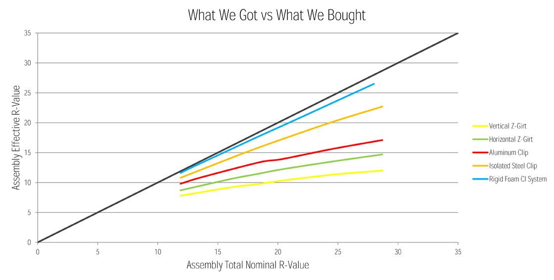
The same challenge of deteriorating insulating values can be seen on exterior insulated wall assemblies as well, where only a fraction of the insulation's stated R-value is actually delivered. As will be discussed later in detail, using a typical continuous furring channel for cladding attachment, such as a vertical Z-girt, will only allow the insulation to perform at ±40 percent of its rated R-value. Rotate the cladding attachment Z-girt 90 degrees to the horizontal and the effectiveness of the insulation will only be increased ±50 percent of its rated R-value. Consequently, the building owner, or occupant, is only receiving half of what they actually paid for.
 |
Steel has a small footprint, is non-combustible, and has excellent strength and structural properties. However, it has very poor thermal properties.
Image courtesy of Knight Wall Systems |
There are several characteristics of the cladding attachment methodology and configuration that affect overall thermal performance and can cause thermal short circuits, which can drastically reduce the effectiveness of the insulation. There are three key culprits that affect the exterior insulation's clear wall performance—the amount of material penetrating the insulation, the actual conductivity of the material penetrating the insulation, and the amount of contact area between all bridged/connected parts.
Amount of material penetrating the insulation. With a greater cross-sectional area of material penetrating the insulation, a greater amount of heat energy can be moved. The best way to think of this is an eight-lane interstate versus a two-lane road with the cars analogous of the heat energy. Which one can move more cars (read heat energy) from point A to point B per hour? With material penetrating the insulation, the actual thermal conductivity of the material used for the attachment system will allow for more heat energy to be transferred.
Conductivity of material. It is important to note that every material in the world has the property of thermal conductivity, but some materials are very low in conductivity whereas others are very high. Aluminum has a far greater thermal conductivity than steel. Therefore, more heat energy will be able to flow through a cross section of aluminum versus steel, decreasing overall performance even further. Looking at the road and car analogy, aluminum is a 75-mph interstate whereas steel is a 35-mph street. Which way moves cars, or heat energy in this analogy, from point A to point B fastest?
Contact. How the material contacts the substrate and different pieces within the cladding attachment assembly also has an effect on how heat energy transfers. The greater the contact area between conductive materials, the more heat energy can transfer and move from point A to point B. If we limit contact area, we can “bottleneck” and limit the heat energy transfer. So looking at the road and car analogy one last time, reduction in contact area is like a traffic jam on a busy interstate. The cars (heat energy) are still moving from one point to another, but at a much slower rate since only a limited number of cars can get onto the road at once.
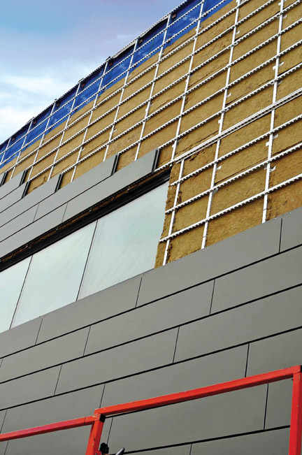
The Rainscreen Edge
One option to complying with code requirements is a properly deployed rainscreen, which is an exterior cladding infrastructure that sits away from a building's outside wall's weather-resistant barrier, creating an air cavity directly behind the cladding that helps to protect the building's important weather-resistant barrier. This allows any moisture that may pass by the cladding to easily drain away from the building, and the air that flows between the cladding and the wall due to convection accelerates evaporation of any residual moisture. A rainscreen should be viewed as a building envelope support mechanism, whose primary function is not to provide barrier protection against water penetration (such as a weather-resistant barrier does). Rather, a rainscreen is designed to limit the amount of water that could potentially come into contact with the primary building envelope's moisture barrier, thereby reducing the chance of water finding a way into the wall assembly. It does this by defending the wall assembly against the five forces that drive rain into buildings: kinetic energy, gravity, capillary action, surface tension, and pressure gradients.
Not all rainscreens are created equal, however, and how they are attached to the building envelope can make a significant difference. Two viable approaches to reducing thermal bridging are mineral fiber and rigid foam rainscreen systems. The former reduces thermal bridging via the use of thermally isolated steel brackets, and the latter by thermally isolated screw attachments through the rigid insulation where no metal penetrates the insulation except for the fasteners, thus meeting the definition of ci. Essentially accomplishing the same thing, these systems can be specified according to user preference. Rainscreen attachment methods used in conjunction with rigid foam are the most thermally efficient and the thinnest energy code compliant wall assemblies since there is so much less metal penetrating the exterior insulation. The thermally isolated steel brackets used in conjunction with mineral fiber systems is far more efficient than any other mineral fiber cladding attachment approach, including brackets made entirely of low conductive fiber reinforced polymers. Though the use of a bracket for attachment does not conform to the code definition of ci, it does meet code via the prescriptive U-factor.
 |
|
Image courtesy of Knight Wall Systems |
While the manner in which exterior insulation has been typically added to wall assemblies decreases the insulation's thermal performance by half, isolated steel brackets in rainscreen construction can result in increased insulation effectiveness, up to 90 percent over traditional methods. When only thermally isolated screw fasteners penetrate the insulation, 98 percent effectiveness can be achieved.
Mineral fiber systems. These systems may be installed over many substrates including steel studs, wood studs, CMU, clay, and concrete. Live loads imposed upon the system (primarily wind pressures) paired with the substrate type will dictate the size of anchors and spacing required to achieve proper pull-out strength. Some manufacturers use small, triangular, intermittent wall brackets that allow direct attachment of vertical or horizontal rails. Having this flexibility built into the attachment configuration frees designers to layout façade panels any way they'd like, especially if secondary rails are added to the attachment assembly. The small steel brackets are anti-corrosive coated and include a durable plastic base and integral plastic washer. With such a system, only a ribbed area of the plastic base touches the wall substrate, significantly reducing thermal bridging at that point of contact, a particular area of the building envelope that can potentially contribute to heat loss and gain. A plastic cap isolates the stem of the wall bracket from the rail to further decrease any thermal transfer from the bracket to the rail. There is no metal-on-metal contact, which is the key to the brackets' effectiveness.
These assemblies have also been seen to incorporate built-in methods of plumbing the façade during installation. One way to accomplish this is by allowing the rails' connection with the bracket to be variable so the installer can adjust on the fly. The second option involves adding specially designed shims between the thermal isolator and sheathing. Isolator shims are provided to fit square, straight, and flat to the back of the system via raised lips that lock the shim in-place for a structurally secure and sound connection without affecting thermal transmittance negatively. Typically, manufactures create air cavities anywhere from 0.75 inch to 1.5 inches depending upon rail configuration and panel requirements. Such rainscreen attachment systems can be used with mineral fiber while providing close to the same energy-efficiency of a true continuous insulation rainscreens.
 |
A bracket typically used with mineral fiber insulation. Note the webbed thermal isolation base which not only reduces thermal transfer due to lower conductivity, but also reduces contact area with the substrate by approximately 60%.
Photo courtesy of Knight Wall Systems |
Rigid foam system. Approaches for rainscreen attachment with rigid foam consist of continuous vertical girts which rest outboard of the insulation, and optional horizontal tracks, to mount a variety of cladding types. The vertical girts resting on top of the 25 psi compressive strength rigid insulation are secured by thermally isolated fasteners penetrating through the continuous exterior insulation and into the substrate. Not only does this system approach comply with code requirements for ci, but thermal modeling shows that the thermal isolators on each fastener will reduce “fin effects” which can reduce wall assemblies by as much as R-1. As with mineral fiber bracket systems, live loads imposed upon the system (primarily wind pressures) and substrate type will dictate the size of anchors and spacing required to achieve proper pull-out strength for long lasting performance. Continuous insulated rainscreen systems give designers and owners the ability to create the thinnest profile, code-compliant, exterior-insulated wall assemblies possible.
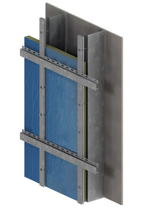 |
Rigid foam system with a properly designed high-bending strength girt and no thermal bridges other than fasteners.
Photo courtesy of Knight Wall Systems |
Accurate Comparisons—Third-Party Testing
Rigorous models have compared these two system approaches to conventional methods. Since heat transfers through an assembly in three dimensions: outward (or inward) through the wall, up the wall and laterally across the wall all at the same time, the best and most accurate way to calculate the overall thermal resistance of a wall assembly is by use of 3D thermal modeling software. For the 3D thermal analysis, many manufactures have used the expert services provided by third-party testing. This testing utilizes the same 3D heat transfer software and algorithms used to model the heat flow on the space shuttle's ceramic/composite tiles when re-entering Earth's atmosphere. However, with any computer modeling “junk-in equals junk-out,” and therefore calibration of the software must be completed for proper data results. This software has been calibrated within 5 percent of dozens of real world building ASTM “hotbox” tests and is considered to be one of the world's most accurate 3D building heat flow models to date.
In both cases, because the backup wall plays a small role in thermal bridging, the onus is on the cladding attachment system to play the most important role in the thermal resistance of the assembly.
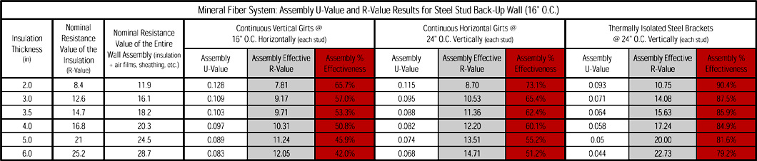
Mineral fiber system. The study investigated the clear wall thermal performance for varying levels of exterior insulation of a mineral fiber system for steel stud backup walls, with and without stud cavity R-19 batt insulation. The mineral fiber system was compared with two other common cladding attachments, continuous vertical and horizontal Z-girts. It is important to note that the overall wall assemblies did not change in configuration at all, except for the cladding attachment methods.
For the vertical steel Z-girt assembly, the girts bypass the exterior insulation and are in line with the steel studs at 16 inches o.c., which creates a direct path for heat to flow past the insulation. As a result, the thermal resistance of the assembly with the vertical system is between 42 to 68 percent effective compared to the nominal resistance of the assembly. In fact, as more mineral fiber insulation is added to the assembly, the percent effective decreases. This is commonly referred to as the property of diminishing returns. Even if double the amount of insulation is added to the assembly the resulting real R-value (effective R-value) increases only fractionally. It is not a linear relationship.
Using horizontal girts spaced at 24 inches o.c., the direct heat flow from metal to metal is reduced, the overall amount of steel penetrating the insulation is reduced, and the thermal resistance values are improved compared to the vertical Z-girt assembly. However, the girts still bypass the exterior insulation, and the property of diminishing returns is still quite evident as the effectiveness of the assembly's thermal resistance is between 52 to 75 percent.
With the thermally isolated bracket mineral fiber system, the amount of material bypassing the insulation is greatly reduced by using the triangular brackets, which are also spaced off the sheathing with low conductivity, durable, plastic isolator pads at each stud, 24 inches o.c. By reducing the cross-sectional area of metal penetrating the insulation, decreasing the contact area with the ribbed plastic base, and placing low conductivity material between interconnected steel parts, the result is an effective thermal resistance between 80 and 93 percent for the assembly. Again, the property of diminishing returns is evident, but has far less impact compared to other assemblies.
The model showed that with 80-93 percent exterior insulation effectiveness, this system can meet the requirements of ASHRAE 90.1-2007/2010 in all climate zones with only 3.5 inches of exterior mineral fiber insulation without the need for interior batt insulation. Overall, the thermal performance of the modeled mineral fiber system was found to outperform the continuous vertical and horizontal girt systems.
When the thermally isolated bracket was modeled with R-19 batt insulation added to the stud cavity with exterior mineral fiber insulation, an average of R-8.3 was added to the total assembly effective R-value.
 |
Click to view large table image
Courtesy of Knight Wall Systems |
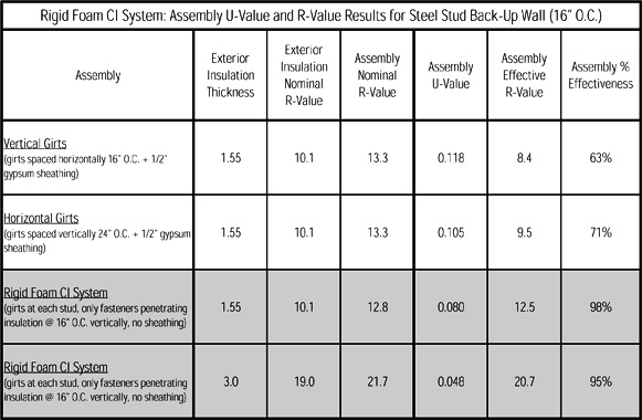
Rigid foam ci system. In another study using this software the third-party testing investigated the clear wall thermal performance of a continuous insulated attachment system with isolated thermal brackets for two exterior insulation thicknesses, two fastener spacings and with and without interior sprayfoam. These configurations of the ci-system were compared with two commonly used cladding attachment systems with similar exterior and interior insulation levels. Modeling the systems without interior insulation was done to better evaluate the effectiveness of just the exterior cladding attachment arrangements
The first base assembly analyzed includes steel studs at 16 inches o.c., interior spray foam insulation (R-9.8), 1.5 inches of exterior insulation, and various attachment configurations. The continuous vertical girts penetrating the insulation were found to create a direct heat flow path to the studs, bypassing both the exterior and interior insulation. As a result, the effective assembly thermal resistance is only 50 percent of the nominal value of the assembly (resistance of the wall if there was no thermal bridging). While the continuous horizontal girt system reduces the overlap of steel parts by running perpendicular to the studs, the girts still bypass the exterior insulation. This results in a 66 percent effectiveness of the assembly thermal resistance compared to the nominal values.
 |
Click to view large table image
Courtesy of Knight Wall Systems |
If the interior insulation is removed out of the assembly and only the exterior insulation is analyzed, the results change drastically. In interior insulated assemblies, steel studs produce a large amount of thermal bridging. For penetrating vertical girt systems, there is a similar amount of thermal bridging through both the exterior and interior insulations. Therefore, an exterior insulated assembly with 1.5 inches of rigid foam insulation and penetrating vertical Z-girts has a very low effective R-value. The effectiveness of the insulation for this case is only 63 percent.
Again, if the interior insulation is removed and only the exterior insulation is analyzed, but with penetrating horizontal Z-girts, the system has, overall, less thermal resistance as expected. However, the horizontal z-girt system uses the insulation slightly more effectively since the insulation is only on the exterior of the wall and the girts are spaced farther than the steel studs. With this assembly, the effectiveness of the exterior insulation is 71 percent. This is still far from the nominal, rated, R-value of the insulation.
With a rigid foam continuous insulation system, the penetrating continuous girts are replaced by stainless steel fasteners, which penetrate the exterior insulation at limited locations (8 inches o.c. vertically), reducing the amount of steel bypassing the insulation, making the system 80 percent effective. This includes the effects of thermal bridging from the steel studs through the interior spray foam, driving down the overall percent effective of the assembly as a whole.
Increasing the exterior insulation thickness to 3 inches increases the nominal R-value of the exterior insulation by R-8.9. Overall, this system has a much higher effective assembly thermal resistance than the previous cases as one would expect, and the effective thermal resistance is, again, 80 percent. The overall percent effective of the assembly as a whole is once again lower due to the effects of thermal bridging from the steel studs.
If the spacing of the fasteners is changed to a more practical and typical spacing of 16 inches o.c. vs 8 inches o.c. vertically, the effect on the overall thermal resistance increases by just less than an R-1 for 1.5 inch insulation thickness, creating an 83 percent effectiveness vs 80 percent.
Replacing the 1.5 inches of rigid insulation with 3 inches of insulation while increasing the fastener spacing boosts the system's thermal resistance by R-1.4. The reason for the increased thermal resistance is as more insulation is added, more heat will try to flow out of the screws. As result, changing screw spacing's will have a greater effect. This increases the effectiveness of the thermal resistance to 86 percent.
With interior insulation in the ci attachment system, significant gains with reduced bridging in the exterior insulation are blurred by heat flow bypassing the interior insulation through the stud cavity. Without stud cavity insulation, the effective R-value of the assembly as a whole is R-12.5. This is within less than half an R-value compared to the total nominal resistance of the assembly (R-12.8), which is 97 percent effectiveness.
Again, replacing the 1.5 inches of rigid insulation with 3 inches of insulation and removing the insulation within the stud cavity, the difference between the nominal and effective assembly R-value is only R-1. As with any insulated assembly that contains thermal bridges of any kind, there is still a diminishing return with increasing insulation; however this decrease is minor and the system is still 95 percent effective, indicating that the exterior fasteners are very effective in reducing thermal bridging through the exterior insulation compared to penetrating continuous vertical or horizontal girts.
 |
|
This figure summarizes the insulation effectiveness for various assemblies. Click to view large table image.
Courtesy of Knight Wall Systems |
Cost Implications
The performance of a wall has several implications. First, it has a dramatic effect on a building's operational expenses. With the average cost of a kWh of electricity in 2011 at nearly 12 cents (eia.gov), reducing heating and cooling HVAC workloads can translate to substantial cost savings over the life of a building. When an R-19 batt insulated steel framed wall, 4-inch deep vertical and horizontal Z-girt assemblies and a 4-inch deep thermally isolated intermittent bracket system are compared for kWh/SF used, the bracket system shows superior performance. The intermittent bracket system reduces heat transfer through assemblies so that space heating power uses ± 55 percent less kWh compared to batt and ± 38 percent and ± 28 percent less compared to vertical and horizontal Z-girts respectively. Being that a thermally isolated intermittent bracket system has less thermal bridging and performs much better than continuous furring strips, the overall thickness of insulation required for code compliance is reduced, saving material costs. Furring strips require more than 6 inches of exterior mineral fiber insulation or over 4 inches of rigid foam, whereas some intermittent isolated bracket systems can require as little as 3.5 inches of mineral fiber, or a ci attachment system with as little as 2.5 inches of rigid foam insulation. In fact, it is impossible to be at or below a maximum U-factor of 0.064 with steel stud assemblies and continuous vertical or horizontal Z-girts with 6 inches of mineral fiber insulation or less or ±4 inches of rigid foam. Note that there are several types of rigid foams with different R-values, therefore some rigid foams may be 3.5 inches and others 4.25 inches.
By using these techniques to reduce the thermal bridging, not only is the overall performance of the wall dramatically increased, the thickness of insulation required to meet code can be reduced. The result: a decrease in the cost per square foot per R-value of insulation required, and a reduction in overall wall thickness, leaving the owner with more overall useable or leasable floor area. Thinner wall profiles also mean a reduction in trim flashing at windows and doors and associated labor costs. Today it is more important than ever to get the insulation equation right. As the glazing area increases—which it typically does in modern buildings—the importance of the opaque wall assembly's insulation effectiveness increases. High glazing ratios begin to kill the overall efficiency of the entire wall assembly at an exponential rate, so better performing insulation methods become ever more critical to keep energy usage and operating costs in check.
| Hidden Benefit of CI—Elimination of Condensation |
In the accompanying figure, note that the right side is the warm inside, left side is the cool outside. In this illustration, the problem is in the cavity—this is where condensation is most likely to occur. In fact, the danger point is a specific place – on the interior side of the exterior sheathing. With the importance of temperature paramount when it comes to condensation, the most important characteristic to know is the temperature at this location. R-values can be used to determine temperature. Since the R-values to the inside of the wall are much greater than the outside, the danger zone will have a temperature much closer to the outside temperature than the inside temperature. The temperature at the sheathing in this example is 10F, and an interior humidity of only 8 percent would be enough for condensation to form.
Yet if the exterior insulation is dominant, the point of condensation, or dew point, will be dramatically different. This shift in insulation from interior to exterior creates a much warmer stud cavity. With a stud cavity now at the temperature of the conditioned space, the likelihood of condensation is reduced. In short, condensation is a temperature related phenomena, and shifting the position of the insulation has dramatically changed the temperature.
 |
|
Illustration courtesy of Knight Wall Systems |
|
Other Important Considerations of RainScreen Assemblies Effecting Performance
There are several considerations important to realizing the full potential of rainscreen performance.
Material Type
The decision to specify aluminum, steel or other material brackets should be carefully considered. Thermal conductivity is directly related to thermal bridging. As has been mentioned, if something is very conductive penetrating a layer of insulation, it provides a path with very little resistance for the heat energy to transfer right through. Metal with lower conductivity has less thermal bridging and better overall performance. Aluminum is five times more conductive of heat than steel, and 17 times more than stainless steel. While extremely long lasting, manufactured aluminum parts are also more expensive than steel.
With changes in temperature, aluminum's expansion and contraction is over 50% greater than steel, which is generally considered the more stable material. Although the amount of expansion is usually a small percentage, the effects of that expansion must be accommodated in the rainscreen design to avoid structural problems. The more complex the design, the more difficult the installation, increasing costs and possibly creating quality control issues.
That is not to say that any type of steel will make for the ideal bracket. Galvanized steel is the most common, but typically has a far shorter lifespan when compared to other steel coatings. Carbon steel coated with anti-corrosive properties ensure metal components have maximum service lives. One option is 55 Al-Zn coated steel (ASTM A792, commonly referenced in the industry as Galvalume, with a grade of AZ55. AZ55 coated steel has up to 3 times the life span of G90 galvanized in the harshest marine atmosphere and over five times in moderate atmospheres. The coating composition of 55 percent aluminum and 45 percent zinc provides corrosion resistance via the presence of microscopic aluminum-rich areas within the coating, which corrode very slowly and zinc-rich areas, which provide galvanic protection. Another coating gaining popularity is Zinc-Aluminum-Magnesium, commonly referred to as ZAM, produced to ASTM A1046. ZAM has outperformed all current steel coatings in a variety of salt-spray tests and has even gained the reputation as being the bridge between stainless and heavy galvanized coatings.
Another option is 304 stainless steel, one of the most versatile and most widely used stainless steels. Composed of 18 percent chromium and 8 percent nickel (otherwise known as 18/8), this grade of stainless steel resists most oxidizing acids and is very corrosion resistant, providing a virtually indestructible surface, and at a surprisingly competitive rate compared to extruded aluminum attachment systems. Remember that stainless steel is 17 times less conductive than aluminum as well.
Installation
A good installation entails more than meets the eye. In order to achieve predicted performance, the rainscreen insulation installation must be a tight fit, without the gaps and cracks that lead to energy (heat) leakage, a leading cause of energy waste, and potential condensation problems. Even small gaps can reduce efficiency as much as 25 percent, compromising the building's energy performance, driving up operating costs and requiring costly and disruptive callbacks. Considering the way in which the installer must place the insulation on the wall and around the brackets or girts can have a large impact on costs. For example, if brackets are ¾ inches thick penetrating through the insulation, the insulation would have to be carved out by hand around each bracket in order to fit snuggly. If the brackets were only a 1/16 inch thick, such a metal, the insulation would fit tightly, eliminating the need for trimming.
Another installation consideration involves the NFPA (National Fire Protection Agency) 285 fire-test requirement for multi-story, non-combustible construction. While this has been a part of the building code for more than two decades (both pre- and post-merger of the building codes into IBC), for many years designers rarely looked at this requirement or even knew it existed. Recent developments in ASHRAE, IECC and LEED have increased the interest in high performance building envelope designs with continuous insulation, which commonly involve combustible plastic foam.
 |
Note how the insulation is falling away from the wall with the brick tie. Not held back properly leading to condensation points on the wall potentially. Note on the right how using rigid insulation with a bracket system is difficult because it’s very hard to carve out and make it fit tight. If it doesn’t fit tight it will not perform correctly.
Photos courtesy of Knight Wall Systems |
With the increased use of thick foam insulation in sustainable, energy efficient designs, architects should be aware that all foam plastic insulations used in exterior wall assemblies are required to pass all seven elements of Chapter 26 of the IBC, including Section 2603.5.5, which requires compliance with NFPA 285. Foam plastic insulation manufacturers should provide verification that products are part of an approved NFPA 285 assembly. It is important to note that the NFPA 285-2006 standard fire test is an assembly test, not a component test. The details of the test assembly and application materials should be strictly followed in practice.
It is also important to note that the NFPA 285 fire-test does not pertain to all plastics used in exterior, non-combustible construction. A thermoset plastic isolator, such as ones described earlier, does not fall into any category within the IBC that references the requirement for the NFPA 285 fire-test (however another component within the assembly could require NFPA 285). However if the plastic isolator, or plastic bracket, is not simply a thermoset plastic but fiber-reinforced plastic (FRP), then NFPA 285 fire-test requirements will apply.
Conclusion and Wrap-Up
With ever more stringent energy codes, architects and designers must fully understand how to achieve energy efficient buildings. By reducing the thermal bridging, the overall performance of the wall is dramatically increased, and operational costs reduced. The manner in which exterior insulation has been typically added to wall assemblies dramatically decreases thermal performance. Exterior continuous insulation systems and systems with highly engineered isolated steel brackets are one proven way to significantly reduce thermal bridging and lead to optimum performance in a wall assembly with minimal risk.
 |
Award-winning Knight Wall Systems manufactures versatile rainscreen attachment systems that accommodate a wide array of
cladding options with reduced thermal bridging. www.knightwallsystems.com |