This CE Center article is no longer eligible for receiving credits.
Architecture and light: The two are intertwined in good design
of all buildings, but the same is true of building sites.
Outdoor spaces frame and enhance any building design. Depending
on the lighting used, these outdoor spaces can create settings
that might be attractive or mysterious, inviting, or secluded,
secure-feeling or foreboding. With buildings and spaces being
used during more hours of the day and night, good site lighting
design becomes as important as good building lighting design.
Outdoor lighting, like all artificial illumination, is based
on an understanding of light principles and the specification
of luminaires that meet one's objectives. A luminaire
is defined by the Illuminating Engineering Society of North
America (IESNA) as "a device to produce, control, and
distribute light. (It is) a complete lighting unit consisting
of the following components: one or more lamps, optical devices
designed to distribute light, sockets to position and connect
the lamps to a supply of electric power, and the mechanical
components required to support or suspend the housing above
grade."
From a pure lighting standpoint, the main items that differentiate
luminaires are the internal optical system and the lamp (bulb)
unit. The function of an optical system is to direct light
energy emitted by the lamp into desirable areas. This function
can be accomplished through reflection, diffusion, baffling,
refraction, or transmission through a lens. Lamp placement
within the luminaire also plays a significant role in determining
optical system performance. Using the lamp's natural
distribution pattern to its greatest advantage produces the
most effective optical designs. For example, a horizontal
lamp orientation produces asymmetric light distribution patterns,
while vertical lamp orientation produces a strong symmetric
pattern. Reflector and lens designs that enhance these characteristics
produce the most efficient results.
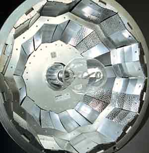
Photo Courtesy
Kim Lighting |
|
|
IESNA also identifies performance and design considerations
as follows, "Luminaire performance can be considered
a combination of photometric, electrical, and mechanical performance.
Photometric performance of a luminaire describes the efficiency
and effectiveness with which it delivers the light produced
by the lamp to the intended target." Luminaire manufacturers
need to consider a wide variety of factors in designing and
producing their products. Architects and other design professionals
need to be aware of fundamental criteria in designing lighting
layouts and specifying luminaries for use on their projects.
I. SITE LIGHTING AREAS AND DESIGN INTEGRATION
Any given building site usually has
differing uses and conditions-each has differing lighting
requirements as well. Therefore, meeting the diverse
needs of site illumination requires a variety of different
solutions that can be coordinated and integrated to complement
the building design. Such an integrated site lighting design
begins with first identifying the specific lighting requirements
for each portion of the site, then selecting luminaires that
combine appropriate aesthetic design with relevant lighting
performance features.
Conceptually, project sites can be classified into four basic
lighting areas; roadways, open areas, pedestrian areas, and
the site perimeter, each representing a unique set of lighting
circumstances, as described below and shown in Figure 1.
 Figure 1: Typical
Site Lighting Areas
Figure 1: Typical
Site Lighting Areas |
|
1. Roadways
2. Open Areas
|
3.
Pedestrian Areas
4. Site Perimeter |
|
|
1. Roadways
Lighting for roadways, including private drive lanes, usually
requires uniform light distribution and glare control with
wide pole spacings to minimize the total number of luminaires
needed. Luminaire selection criteria include overall performance,
consideration of maintenance, lamp choices influenced by utility
or owner interests, and the ability to remain in service for
long periods with minimal attention. Reflectors and optical
designs within the luminaires include an array of possible
light distribution patterns in order to illuminate varied
roadway widths and traffic patterns with narrow perpendicular
and wide lateral beam spreads.
2. Open Areas
Lighting of open areas requires careful consideration of illumination
requirements, uniformity, and brightness control. These areas
are usually subject to scrutiny relevant to the safety and
security of site occupants and the interaction between vehicle
and pedestrian traffic. Parking areas and connecting walkways,
in particular, are a potential source of litigation and liability
for the project owner, requiring accurate prediction of illumination
levels and dependable performance. In order to optimize visibility
for all users, it is important to control illumination levels,
uniformity of light distribution, and glare. At the same time,
an economical layout will be based on maximizing the spacing
of luminaires.
3. Pedestrian Areas
The transition between the surrounding site and the building
itself defines the pedestrian area, including plazas, courtyards,
and pathways. These spaces require the widest range of lighting
solutions since they combine the concerns of open areas and
the integration of luminaire appearance with the building's
architectural design. Luminaires in this area are usually
highly visible, requiring attention to finish quality and
detail. Illumination of irregularly shaped spaces, and a need
to control stray light, requires optical diversity, particularly
since fixture placement may be influenced by aesthetic concerns.
Ideally, if the appearance and design components of the luminaires
specified in these areas are shared with other site luminaires,
the integration of the lighting system for the entire site
is enhanced.
4. Site Perimeter
Lighting the site perimeter includes requirements to control
or eliminate illumination from "trespassing" onto
adjacent properties. Light trespass ordinances, and courtesy
to neighboring property occupants, require tight control of
light emitted behind the luminaire. Efficient design satisfies
some of this demand, while optics inside the luminaire that
cut off light distribution in certain areas provide an additional
level of control. House-side shields may also be required
to provide even tighter control by trimming the distribution
pattern. These concerns must be satisfied, of course, without
affecting overall system performance.
II. PHOTOMETRY INFORMATION
The design of site lighting requires an understanding of
the unique information used to represent elements of optical
performance. Photometry, or the measurement of light intensity
and relative illuminating power, is the foundation on which
any evaluation of luminaire performance is based. Use of independent
testing labs to conduct the measurements and compile the information
ensures that the photometry information is accurate and reliable.
Basic Language and Presentation
In order to properly select luminaires appropriate to the
specific locations and requirements of a building site, an
understanding of some of the basic language and ways that
information is presented is required.
 Figure 2: Candela
Tabulation Data
Figure 2: Candela
Tabulation Data |
|
|
Candela Tabulation
One of the fundamental units of measurement is the candela,
which in 1979 became the international standard to define
luminous intensity. Figure 2 shows a typical candela tabulation
data sheet prepared by an independent lab with a luminaire
orientation diagram for reference.
The Candela Tabulation Data Sheet presents the raw data used
for all illuminance calculations and is tabulated with the
vertical angles in rows and lateral angles in columns. As
the diagram indicates, lateral values from 0° to 90°
are in front of the luminaire and referenced as "Street
Side." Lateral values from 90° to 180° are behind
the luminaire and referenced as "House Side."
Vertical values from 0° to 90° are below the fixture,
while values 90° to 180° are at the fixture level
and above. As we will see, candela data is also used to define
a luminaire's light distribution type and cutoff characteristics.
Footcandle Calculations
The data provided in Candela Tabulation Data Sheets is used
to calculate footcandle levels within a proposed lighting
design. Generally, this is accomplished by using computers
to make calculations, which are, in turn, dependent upon the
accuracy of the data. Figure 3 illustrates the relationship
of the calculated illumination at a single point to the information
provided in the candela tabulation. (See Figure 7 later in
this article for the correlating location on an isofootcandle
plot.)
 Figure 3: Footcandle
representation based on Candela Tabulation
Data
Figure 3: Footcandle
representation based on Candela Tabulation
Data |
|
|
Candela Plots
Candela plots are graphical representations of candela tabulation
data (figure 2). Outdoor lighting produces unique light patterns
which are difficult to represent in a flat two-dimensional
plane. Therefore, to create distribution plots that illustrate
luminaire performance, curves are plotted with a three-dimensional
dynamic. An example, based on the candela tabulation data
above, is presented in the charts shown in Figure 4.
Using the tabulated maximum candela value, which in this
example is 8595, two planes are identified: a lateral angle
of 71°, and a vertical angle of 66°. The vertical
angle is used to create a cone, with its slope equal to the
vertical angle of maximum candela (66°). On this cone,
all lateral candela distribution values from the tabulated
data row at 66° are plotted. The result is shown on the
right side of the cone chart. The two-dimensional view looks
down at the top of the constructed cone.
|
|
 Figure 4: Maximum
Plane and Cone Plots of Candela
Figure 4: Maximum
Plane and Cone Plots of Candela |
|
|
The second value, the lateral angle of 71°, is used to
construct a vertical plane off the lateral baseline. The result
is shown on the left side of the cone chart. On this surface,
all vertical candela distribution values from the tabulated
data column at 71° are plotted. For purposes of presenting
the plot, the vertical plane is flattened, or laid back 90°,
to show it in the same plane as the right side plot.
The chart is also shown in a perspective view, to help visualize
the relationship between the two plotted curves. The combination
of the two curves represents luminaire performance in three
dimensions.
III. LIGHT DISTRIBUTION PATTERNS
Outdoor luminaires produce lighting patterns that can be
identified first by their reach in front of a single fixture
location and second by their reach on each side of that location.
"Distribution types" describe the reach of the luminaire's
light pattern forward of each fixture, while "distribution
ranges" define the reach to either side.
 Figure 5: Grid and
light patterns to determine Distribution
Type
Figure 5: Grid and
light patterns to determine Distribution
Type |
|
|
Distribution Types
(Refer online for example illustrations of each Distribution
Type).
The term "distribution type" defines how far forward
of the luminaire (i.e., on the street side) the effective
output reaches. The specific classification of distribution
types is based on locating the luminaire's effective
major output pattern on a grid representing distances in units
of Mounting Height (MH) from the luminaire. This pattern is
defined by tracing an area representing light distribution
at 50% of maximum candela. By measuring where the bulk of
this pattern falls on the grid, a luminaire can be classified
as follows and as shown in Figure 5. Refer to illustrations
of definitions online. (Note that in some cases, minor deviations
in a beam pattern may cross the boundary from one type into
another. While this has a nominal effect on applied performance,
it should not be considered for classification purposes.1):
- Type II defines shallow reaches, when the 50% maximum
candela trace lies within1.75 MH on the street side of the
reference line.4
- Type III is a mid-range, when the 50% maximum candela
trace lies within 2.75 MH on the street side of the reference
line.4
- Type IV identifies luminaires with a definite forward-throw
distribution, when the 50% maximum candela trace lies beyond
2.75 MH on the street side of the reference line.4
- Distribution is classified as Type V Square for horizontal
lamp luminaires when
the 50% maximum candela trace is symmetric in four quadrants.
This distribution is characterized by four candela peaks,
diagonal to the reference line.
- Asymmetric5,6 Distribution (similar to Type III): This
distribution is for vertical lamp luminaires when the 50%
maximum candela trace lies beyond 1.0 MH on thestreet side
of the reference line, and inside 1.0 MH on the house side
of thereference line. Narrow range distribution is identified
when the point of maximum candela falls inside of 2.25 MH;
wide range is identified when the point of maximum candela
falls beyond 2.25 MH.
- Symmetric5,6 Square Distribution (similar to Type V Square):
Distribution is classified as symmetric square for vertical
lamp luminaires when the 50% maximum candela trace is symmetric
in four quadrants on both street and house side of the reference
line. Narrow range distribution is identified when the candela
peaks fall inside of 2.25 MH along the reference line; wide
range is identified when the candela peaks fall beyond 2.25
MH.
Distribution Range
Distribution range defines how far the distribution pattern
reaches laterally, perpendicular to the axis used to identify
general type. The ranges used are defined as follows and indicated
graphically in Figure 5.
Long Range: A distribution
is identified as long range when the point of maximum candela
lies from 3.75 to 6.0 MH from the luminaire's centerline,
along the reference line.
Medium Range: A distribution
is identified as medium range when the point of maximum candela
lies from 2.25 to 3.75 MH from the luminaire's centerline,
along the reference line.
Short Range: A distribution
is identified as short range when the point of maximum candela
lies from 1.0 to 2.25 MH from the luminaire's centerline,
along the reference line.
Very Short Range²: A distribution
is identified as very short range when the point of maximum
candela lies from 0 to 1.0 MH along the reference line.
Distribution types only generally describe a distribution
pattern. To establish the suitability of a luminaire for a
specific application, an evaluation must be completed using
actual photometric data for the specific fixture and lamp
combination being considered.
IV. CUTOFF
Beyond distribution and range, luminaires are defined by
how well they control or cut off light at selected vertical
angles. Typically this reference point is referred to as zero
degrees vertical or "nadir". Designs without significant
cutoff characteristics distribute light in zones unlikely
to contribute to useful visibility, contribute to light pollution,
and are inefficient.
 Figure 6: Definitions
of Cutoff Luminaires
Figure 6: Definitions
of Cutoff Luminaires |
|
|
Definitions
The definition of cutoff is based on what proportion of a
luminaire's output is being distributed at 80° and
90° above nadir. See figure 6 for graphic examples of
some of the luminaire cutoff types defined below. (Extracted
from IES Publication RP33-99 (2/99))
Noncutoff
A luminaire's light distribution is designated as noncutoff
when there is no limitation of illumination in any zone.
Full Cutoff
A luminaire's light distribution is designated as full
cutoff when the candela at 90° above nadir is 0 and less
than 10% of rated lamp lumens at 80° above nadir.
Cutoff
A luminaire's light distribution is designated as cutoff
when the candela at 90° above nadir is less than 2.5%
of rated lamp lumens, and less than 10% of rated lamp lumens
at 80° above nadir.
Semicutoff
A luminaire's light distribution is designated as semicutoff
when the candela at 90° above nadir is less than 5% of
rated lamp lumens, and less than 20% of rated lamp lumens
at 80° above nadir.
Example:
A luminaire with tested data showing a total of 16,000 Rated
Lamp Lumens has a candela tabulation that produces 18 candela
at 90° (<2.5% of Rated Lumens) and 55 candela at 80°
(<10% of Rated Lumens). These values fall within the defined
ranges shown in Figure 6, classifying this as a cutoff luminaire.
VI. ISOFOOTCANDLE PLOTS
Isofootcandle plots are a common tool for evaluating and
comparing different luminaires for a given application. These
plots are often provided by luminaire manufacturers for architects
and engineers to use in selecting and specifying appropriate
lighting products. An example is shown in Figure 7.
Usage
Isofootcandle plots graphically represent a particular luminaire's
lighting pattern, in illuminance, as the light strikes a horizontal
surface. These plots are scalable as they are represented
in mounting height increments. An approximation of pole spacings
required to attain a desired light level can easily be determined
from the information provided. These plots also provide a
productive tool for the comparison of various luminaires.
The easily read visual reference indicates beam patterns graphically,
where other information (such as candela tabulations and isocandela
curves) may be less clear.
Conventions
Isofootcandle plots include footcandle calculations shown
with the luminaire at various mounting heights. Contour lines
are drawn through illuminance values. Each contour, from the
center out, represents approximately 50% of the value of the
previous contour. The plot of contours is placed over a grid
indicating mounting height divisions to demonstrate the luminaire's
applied performance.
 Figure 7: Elements
of a typical Isofootcandle plot
Figure 7: Elements
of a typical Isofootcandle plot |
|
|
Estimated Spacing and Uniformity
As early as the schematic design phase of a project, isofootcandle
plots can be used for rough luminaire layouts for site lighting.
EXAMPLE: Refer to the isofootcandle
plot in Figure 8 and assume a desired minimum initial illuminance
of 2.0fc, using luminaires mounted on 14' poles. To estimate
a fixture layout, start from the perimeter, where the 2.0fc
isofootcandle trace crosses the reference line, to establish
the maximum single fixture distance to the site perimeter
(1.6 MH). In order to attain the minimum illuminance (2.0fc)
between fixtures, the 1.0fc traces of two fixtures must intersect
at the site perimeter and interior. Therefore, lateral spacing
is determined where the 1.0fc trace intersects the reference
line (2.2 MH), and maximum forward spacing is identified where
the lateral spacing line intersects the 1.0fc trace on the
street side of the luminaire (1.8 MH). These two dimensions
indicate the mid-points between luminaires, in mounting heights.
Multiplying these mounting height (MH) dimensions by the pole
height (14') defines the maximum luminaire spacings in both
directions. In this example, 60' (4.4 MH x 14') x 50.4' (3.6
MH x 14').
Approximate Illuminances and Uniformity
By overlaying isofootcandle plots, a rough idea of illuminances
can be determined by adding the values of each contour where
they intersect as shown in the lower portion of the example
in Figure 8. Through observation of the overlapping of the
isofootcandle plots, approximate uniformity can also be estimated.
More accurate calculations (computer generated evaluations)
will generally return levels higher than those achieved using
this method, as smaller contributions from every adjacent
luminaire would be included.
VII. APPLICATION IN DESIGN
Distribution Pattern Uses
Ideally, all light energy produced would be focused into desired
lighted zones with no wasted energy being directed elsewhere.
This would require an infinite array of distributions, and
the ability to tune them to every site condition. While this
is not realistic, the combination of careful luminaire selection,
mounting height, and luminaire placement can produce very
efficient designs, using just four basic distribution patterns,
as shown in Figure 9. For each of the basic distributions,
variations such as range and the characteristics of horizontal
vs. vertical lamp optics produce additional choices. Further
fine tuning can be attained with house-side shields and reflector
orientation.
|

|
|
For the past 70 years, Kim Lighting
has produced innovative, architecturally relevant,
performance oriented lighting products designed
for the outdoor environment. Kim combines high
performance optical systems, the highest quality
materials, the latest manufacturing technologies
and practices to complement the architecture in
a variety of applications. Kim Lighting is the
recognized industry leader in outdoor lighting
products that include roadway, area, site, pedestrian
area, pathway landscape, building mounted, and
parking garage lighting applications.
|
|
The sample site plan in Figure 10 shows how the combination
of these four basic distribution patterns are used to direct
light energy into the lighted zones.
|
|
 Figure 8: Example
Isofootcandle plot and spacing.
Figure 8: Example
Isofootcandle plot and spacing. |
|
|
Important Features for Fine-Tuning Designs
Lamp Orientation: Horizontal
lamp orientation provides the greatest control over lateral
distribution. The normal lamp distribution is very well suited
for asymmetric as well as square symmetric distribution. Horizontal
lamp orientation produces relatively small arc tube exposure
to high distribution angles. This produces a superior cutoff
characteristic.
Vertical lamp orientation subjects the greatest portion of
the lamp's output to control by the reflector system,
producing optimal vertical distribution control. This orientation
provides less control over lateral output, favoring symmetric
distribution patterns. Vertical lamp orientation also takes
advantage of the higher lumen output produced by a vertical
arc tube positioning.
 |
 |
|
Type
II
Type II distributions
are well suited for narrow areas, running
parallel to the luminaire's reference
line, such as roadways, paths and driveways.
|
Type
IV
Type IV distributions
produce a deep forward throw, well suited
for perimeter lighting.
|
 |
 |
|
Type
III - Horizontal Lamp
Asymmetric - Vertical Lamp
Type III and Asymmetric
distributions are well suited for site /
area perimeters, wide roadways, and open
areas.
|
Type V Square - Horizontal
Lamp
Symmetric Square - Vertical Lamp
Type V and Symmetric
distributions produce a wide, symmetrical
pattern with excellent uniformity for large,
open areas.
|
|
Figure 9: Four basic distribution
patterns.
|
|
|
 Figure 10: Sample
site plan showing light distribution
Figure 10: Sample
site plan showing light distribution
pattern with different distribution types
|
|
|
Square vs. Round Distribution:
For large areas, symmetric distributions provide maximum pole
spacing in both lateral and longitudinal directions. Round
distributions, however, do not reach well diagonally between
pole locations, reducing uniformity and requiring shorter
distances between luminaires. Square distribution patterns
are specifically engineered to maximize pole spacing by improving
uniformity diagonally between fixture locations. As shown
in Figure 11, a typical round pattern produces poor diagonal
overlap, requiring tighter pole spacing to maintain acceptable
uniformity. A Type V Square Pattern provides improved diagonal
overlap allowing wider pole spacing while maintaining excellent
uniformity.
House-Side Shields: When luminaires
are located close to structures, or areas where the illumination
emitted on the house-side of the reference line is objectionable,
house-side shields offer additional cutoff control. These
devices essentially trim light emitted by the lamp, as well
as light reflected from within the optical system. These are
applied to Type II, Type III and Type IV (horizontal lamp)
and Asymmetric (vertical lamp) optical systems only as shown
in Figure 12. House-side shields are not applied to Type V
or Symmetric optical systems, as the shields will not function
properly in these systems.
 Figure 11: Typical
Round vs. Square Overlap patterns
Figure 11: Typical
Round vs. Square Overlap patterns
|
|
|
It should be noted that the effects of lamp orientation and
lens configuration on house-side shields are dramatic. Main
reflector distribution, street-side reflector brightness,
and direct lamp visibility are factors that determine the
effectiveness of house-side shields in reducing unwanted brightness
on the house-side of the optical system. Horizontal lamp orientation
presents the greatest challenge in designing effective shielding.
Convex lenses allow more effective control, as the shielding
device is able to better control direct arc tube brightness.
Vertical lamp orientation provides even greater control, as
the arc tube is already deeper in the optical system.
Reflector Orientation/Rotatable Optics
Orientation of luminaires is often controlled by available
pole locations and a product's aesthetic design. The luminaire's
head, arm, or yoke, however, may dictate an orientation that
varies from the desired optical orientation. The ability to
rotate optical systems provides a high degree of flexibility
to tailor luminaire performance to specific applications,
while maintaining the aesthetic continuity of the luminaires
used. The combination of optical distributions in multiple
luminaire applications produces additional unique "footprints,"
creating customized performance and/or increased illumination
levels to suit a very wide range of needs. Figure 13 shows
just a few examples based on a simple twin mounting arrangement.
 Figure 12: House-side
shields for cutoff and light control for
different types of luminaires
Figure 12: House-side
shields for cutoff and light control for
different types of luminaires |
|
|
Footnotes:
- ITL Reports using IES guidelines consider any crossing
of the identified boundaries as definition of overall type,
regardless of its impact or significance to applied performance.
Classifications indicated do not consider minor deviations
in classification of type shown.
- The "Very Short Range" identification is not
an IES standard definition, but isused by ITL to identify
distributions with ranges inside the 1.0 MH allowed in the
"Short Range" definition established.
- Information shown is for illustrative purposes only and
does not represent a specific luminaire's performance.
- Definition is extracted from IES Lighting Handbook, 8th
edition.
- Definition has not been identified by the IES at this
time. Definition shown is based on Kim Lighting research
and development efforts and engineering of optical systems
to improve applied performance.
- Distribution may be classified by ITL, using IES standard
practices, as a Type IV
distribution, due to a small portion of the 50% isocandela
trace falling beyond the 2.75 MH line. This aberration in
classification methodology conflicts with luminaire applied
performance. Classification indicated more accurately represents
actual luminaire usage.
|
Type II
|
Type III, Asymmetric
|
Type IV
|
 Figure 13: Examples
of optics that can be rotated within luminaires
Figure 13: Examples
of optics that can be rotated within luminaires
|
|
|
CASE STUDY
The expansion and beautification of
the Minneapolis Community & Technical College (MCTC) parking
ramp.
Bentz/Thompson/Rietow (BTR), Architects-of-Record
The Minnesota State Colleges and Universities
system (MnSCU) gained control of the MCTC and its associated
power plant and parking ramp. However, the parking ramp, having
had no true upgrades to its exterior and having had a less
than urban-friendly original design, became known as a blight
on the area, poorly representing the college and the site's
importance. The original ramp, built in 1978 for the Minneapolis
Public School system, was one of the first major public design/build
projects. The original design, while inventive in the use
of long-span precast concrete wall panels, did little to harmonize
with its surroundings and little to respond to the importance
of the site, which is truly a spectacular location. The ramp
is located on the major public thoroughfare through downtown,
Hennepin Avenue. This roadway has historically been one of
the storied streets in the city; it is the gateway to the
city from the west and crosses the Mississippi River to the
east, and is known as the entertainment avenue for the city.
After a decline in the area that lasted several decades, this
downtown street has once again established itself as a major
theater district with numerous eating establishments, clubs,
bars, and plenty of nightlife.
Early on, the design team resolved that the project needed
to reinforce the urban edge. The team also posited that the
ramp should have a dynamic façade response that could
change from night to day and could respond to differing light
and climate conditions. In order to balance the need for an
increased height/mass of the façades with the budget,
the team began working with the concept of light structures
that would provide a layering effect and serve as a theatrical
scrim. The material had to be light yet strong, beautiful
yet inexpensive, durable yet open enough to provide a safe
environment for patrons. Heavily anodized, swaged aluminum
floor grating was used because it met all of the design criteria.
This material was used in a vertical application for the light
columns that march down Hennepin Avenue. The same material
was used in horizontal application to serve as the background
scrim for the façades. Mullionless channel glass was
used at the main stair towers to provide natural light into
the stairs and to serve as urban-sized lanterns along the
façade.
The design drastically improves the image of the structure
during the day and, by using materials similar to ones used
on the adjacent campus, finally makes the structure seem to
be part of the same institution. The gentle curves at the
cornice of the scrim and the bay spacing/proportions of the
light columns recall heights, proportions, and details of
an adjacent basilica. The ramp takes a background role to
the basilica during the day. At night, the ramp takes on a
special presence; it becomes a glowing, theatrical piece that
calls attention to the campus and serves as a distinct gateway
to city and the entertainment district.

Photo credit Phillip
Prouse |
|
Figure 14: Photo of MCTC
Parking ramp lit at night.
|
|
|
Exterior lighting design was crucial to the success of the
project. The team realized that lighting and material had
to be synthesized in such a manner that would leverage the
design intent without incurring large construction costs.
Because the existing ramp had drastically different perimeter
conditions in relationship to the scrim motif, the team needed
fixtures that could be mounted in a variety of conditions
while still having the same photometric distribution on the
scrim. The result of this creative and collaborative design
can be seen in Figure 14 (Photo credit Phillip Prouse).
According to Gary F. Milne Rojek, AIA Principal at BTR, "Designers
need to understand what surfaces are going to be lit, what
level of illumination is desirable, what amount of spread
and control is required, and how to coordinate with other
lighting on the project. On our ramp project, it was extremely
important for us to illuminate the horizontally oriented grating
in a very uniform and white light. The uplighting that was
used had a very wide and uniform distribution that evenly
illuminated the horizontal bars yielding the design intent
of a theatrical scrim. The curvature of the grating at the
top of the bands provides a subtle variation in reflectance.
On the vertically oriented column grating, much narrower spread
fixtures were used in order to emphasize the column elements
in front of the scrim. Both of these design concepts had to
be balanced with the distribution and color range of the standard
ramp downlights."
The building owner has high praise for the results. Sally
Grans, AIA, Director of Facilities Planning and Programming
at MnSCU notes, "Other people need to see just how plain
beautiful this once-ugly duckling parking ramp has now become
a jewel! It is rare to see lighting as a work of art and this
parking ramp is now truly artful. My only concern is that
people don't get into car accidents as they slow down
to look at it!"
Security Commentary
Security and site lighting often go hand in hand. There are
some specific details that can help to ensure increased levels
of security (and the perception of security).
Martha J. Droge, an Associate at Ayers/Saint/Gross in Baltimore,
was a police officer before becoming a landscape architect.
She writes and speaks often about site security and offers
the following points:
- Metal halide lights render the vertical plane visible
at a nearer distance than sodium lamps. This is important
from a security perspective because the vertical plane is
where the human face and hands are revealed as one approaches
a person. Seeing the face and hands as soon as possible
increases a pedestrian'ssense of safety and aids security
personnel when patrolling an area.
- Depending on the technology, CCTV cameras and/or night
vision aids can be thrown off by bright lighting. Obviously,
the lighting plan and the security technology/perimeter
surveillance plan should be well-coordinated.
- A lighting plan for a large complex of buildings or campus
should designate certain routes as primary pedestrian routes
after dark. Depending upon the circumstances, the primary
routes might be the most direct paths between major spaces
or parking lots, or the paths that keep pedestrians near
safe, after-darkactivity areas (buildings with people coming
and going, security patrols, positive night life activities,
etc.). Primary paths should receive excellent comprehensivelighting
and welcoming landscapes as cues to pedestrians to take
those paths after dark. Secondary after-hours routes may
have lighting for basic safety, but pedestrians should be
directed to the primary routes after dark through coordination
with campus maps and directions from campus representatives.
Keeping some of these points in mind when preparing an overall
site lighting plan and layout can go a long way toward improved
security conditions in outdoor settings.
Peter J. Arsenault, AIA, NCARB, LEED-AP
is an architect and consultant focused on green building and
sustainable community planning, based near Syracuse, NY.
About the article sponsor: Kim Lighting is known throughout
the world as the premier designer and manufacturer of quality,
high performance, architecturally relevant, outdoor lighting
solutions. Kim has designed and manufactured outdoor lighting
products for over seven decades and now occupies more than
400,000-square feet of factory space in the City of Industry,
Ontario, and La Mirada, California employing over 600 people.
Kim owes a great deal of its success to the core values established
by its founder, F.B. Nightingale; innovate, educate, and never
compromise quality. Kim Lighting, "The Ultimate in Architecturally
Relevant Outdoor Lighting." Learn more atwww.kimlighting.com.