This CE Center article is no longer eligible for receiving credits.
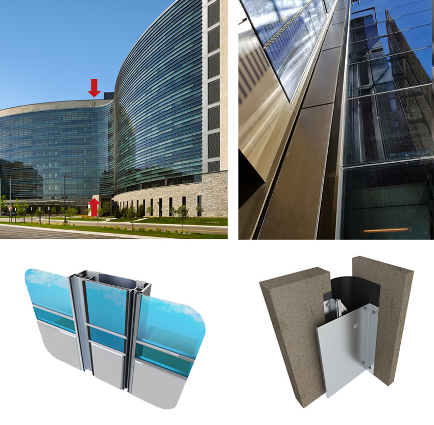
Architectural expansion joints are necessary, predetermined gaps in large structures that are designed to absorb environmental movement in buildings. When done correctly, they tend to be integrated with their construction such that they blend in with a design and almost disappear. Hence, it is easy to overlook the fact that they can be a potential source of water and moisture infiltration and damage. This infiltration could be problematic for the expansion joint itself, or it could cause problems for other building materials or occupants too. Either way, when using expansion joints that need to cut across exterior surfaces, their ability to resist water needs to be factored in along with the other requirements for the joints.

All images courtesy of Inpro
Expansion joints are used in larger buildings to allow movement to occur, but at the same time, they need to provide protection from water intrusion.
This course will look at the ways that expansion joint filler systems can be designed and specified to provide the needed performance characteristics and still remain water resistive. In the process, it will examine the types of moisture and bulk water concerns that need to be addressed, the other performance needs of expansion joints, and the various types of solutions available.
Water and Building Envelopes
Data from the United States Environmental Protection Agency (EPA) indicates that most buildings are likely to experience some form of impact from unwanted or excessive moisture accumulation. Those conditions can lead to serious problems, such as the degradation, deterioration, or even failure of building materials, development of mold and mildew, and possible risks to human health and safety. Repairing any of these conditions after the building is constructed and occupied typically involves opening up construction assemblies, which is disruptive, time-consuming, and costly. Hence, it is no wonder that there is great interest in understanding how moisture can be controlled in buildings to avoid any or all of these potential problems and risks.
The Whole Building Design Guide (WBDG), a program of the National Institute of Building Sciences, provides some of the best, objective, state-of-the-art thinking on this topic. It identifies three main causes of moisture movement: 1) water impingement or leakage (as in a roof, wall, or floor system), 2) movement of moist air (through gaps or openings in roofs, walls, or floors), and 3) vapor diffusion through materials that can occur slowly over time but saturate and damage materials nonetheless. The WBDG points out that solutions cover the gamut of design and construction activities, stating, “Preventive and remedial measures include rainwater tight detail design; prevention of uncontrolled air movement; reduction of indoor air moisture content; reduction of water vapor diffusion into walls and roofs; selection of building materials with appropriate water transmission characteristics; and proper field workmanship quality control.” Listed all together, this may sound like a tall order, but in essence, it means that everyone involved in a building project has a role to play in managing moisture in buildings, starting with the design team.
The potential effects of water and moisture in buildings on human health should not be overlooked either. Wet materials that are organic (e.g., wood, paper, cellulosic, etc.) can become perfect breeding grounds for mold and mildew to form. Many people will react negatively to the release of those spores into the air, causing respiratory ailments or exacerbating existing ones, such as asthma. When those symptoms are found to be connected to the building conditions, issues of professional liability and risk management become top of mind.
Expansion Joints in Buildings
With an understanding of the water issue, let us focus now on an overview of what expansion joints really are and how they are designed into buildings. Expansion joints are fundamentally defined as predetermined gaps in building structures designed to allow for environmental movement. The location, size, and movement requirements for all such expansion joints are project specific and appropriately established by the structural engineer of record.
Recognizing that an open joint in a building needs to be addressed, it is then typically up to the architect to select the means to cover or seal the joint. Common ways to do this can involve caulking or sealant for narrow joints, compressible fillers, or metal covers that are exposed or concealed. The typical traits of an architectural joint cover system include the ability to absorb building movement, support a given load, maintain safe egress where applicable, and be compatible with adjacent surface finishes.
Before looking closer at those filler or architectural cover systems, the following are some things to be aware of regarding expansion joint design in general.
Nominal Joint Size
The design width of an expansion joint at an average air temperature is referred to as the nominal joint size. The selection of any type of joint filler or cover system starts with understanding this nominal joint size and the range of movement between the minimum fully contracted size and the maximum fully expanded size. The expansion joint system selected needs to accommodate this full movement range.
Identifying the nominal joint width and the anticipated movement type that a joint is subjected to is the first step in designing an appropriate expansion joint system.
Type of Movement
Building sections can move due to several common reasons. Thermal movements are most typical and caused by daily environmental temperature changes in and around the structure. Thermal movement is primarily one-directional in nature and is the result of the expansion and contraction of structural elements as affected by heat, cold, and humidity levels. The amount of thermal movement is typically approximately 10–25 percent of the nominal joint size. This means the minimum contracted size (during hot temperatures) should be 10–25 percent less than the nominal joint size, and the maximum expanded size (during cold temperatures) should be 10–25 percent more than the nominal joint size.
Seismic activity can also be a source of movement that may be horizontal, vertical, in shear, or a combination of all three. Seismic joint widths may need to increase with higher floor levels to protect a structure during earthquakes or other seismic events. These joints must have the capacity for movement of approximately 50–100 percent of the nominal joint size.
Finally, wind-load-induced movement, created by high winds, can cause a structure to sway back and forth. Such wind-load-induced movement can be perpendicular or parallel to the joint.
Architectural expansion joints are necessary, predetermined gaps in large structures that are designed to absorb environmental movement in buildings. When done correctly, they tend to be integrated with their construction such that they blend in with a design and almost disappear. Hence, it is easy to overlook the fact that they can be a potential source of water and moisture infiltration and damage. This infiltration could be problematic for the expansion joint itself, or it could cause problems for other building materials or occupants too. Either way, when using expansion joints that need to cut across exterior surfaces, their ability to resist water needs to be factored in along with the other requirements for the joints.
All images courtesy of Inpro
Expansion joints are used in larger buildings to allow movement to occur, but at the same time, they need to provide protection from water intrusion.
This course will look at the ways that expansion joint filler systems can be designed and specified to provide the needed performance characteristics and still remain water resistive. In the process, it will examine the types of moisture and bulk water concerns that need to be addressed, the other performance needs of expansion joints, and the various types of solutions available.
Water and Building Envelopes
Data from the United States Environmental Protection Agency (EPA) indicates that most buildings are likely to experience some form of impact from unwanted or excessive moisture accumulation. Those conditions can lead to serious problems, such as the degradation, deterioration, or even failure of building materials, development of mold and mildew, and possible risks to human health and safety. Repairing any of these conditions after the building is constructed and occupied typically involves opening up construction assemblies, which is disruptive, time-consuming, and costly. Hence, it is no wonder that there is great interest in understanding how moisture can be controlled in buildings to avoid any or all of these potential problems and risks.
The Whole Building Design Guide (WBDG), a program of the National Institute of Building Sciences, provides some of the best, objective, state-of-the-art thinking on this topic. It identifies three main causes of moisture movement: 1) water impingement or leakage (as in a roof, wall, or floor system), 2) movement of moist air (through gaps or openings in roofs, walls, or floors), and 3) vapor diffusion through materials that can occur slowly over time but saturate and damage materials nonetheless. The WBDG points out that solutions cover the gamut of design and construction activities, stating, “Preventive and remedial measures include rainwater tight detail design; prevention of uncontrolled air movement; reduction of indoor air moisture content; reduction of water vapor diffusion into walls and roofs; selection of building materials with appropriate water transmission characteristics; and proper field workmanship quality control.” Listed all together, this may sound like a tall order, but in essence, it means that everyone involved in a building project has a role to play in managing moisture in buildings, starting with the design team.
The potential effects of water and moisture in buildings on human health should not be overlooked either. Wet materials that are organic (e.g., wood, paper, cellulosic, etc.) can become perfect breeding grounds for mold and mildew to form. Many people will react negatively to the release of those spores into the air, causing respiratory ailments or exacerbating existing ones, such as asthma. When those symptoms are found to be connected to the building conditions, issues of professional liability and risk management become top of mind.
Expansion Joints in Buildings
With an understanding of the water issue, let us focus now on an overview of what expansion joints really are and how they are designed into buildings. Expansion joints are fundamentally defined as predetermined gaps in building structures designed to allow for environmental movement. The location, size, and movement requirements for all such expansion joints are project specific and appropriately established by the structural engineer of record.
Recognizing that an open joint in a building needs to be addressed, it is then typically up to the architect to select the means to cover or seal the joint. Common ways to do this can involve caulking or sealant for narrow joints, compressible fillers, or metal covers that are exposed or concealed. The typical traits of an architectural joint cover system include the ability to absorb building movement, support a given load, maintain safe egress where applicable, and be compatible with adjacent surface finishes.
Before looking closer at those filler or architectural cover systems, the following are some things to be aware of regarding expansion joint design in general.
Nominal Joint Size
The design width of an expansion joint at an average air temperature is referred to as the nominal joint size. The selection of any type of joint filler or cover system starts with understanding this nominal joint size and the range of movement between the minimum fully contracted size and the maximum fully expanded size. The expansion joint system selected needs to accommodate this full movement range.
Identifying the nominal joint width and the anticipated movement type that a joint is subjected to is the first step in designing an appropriate expansion joint system.
Type of Movement
Building sections can move due to several common reasons. Thermal movements are most typical and caused by daily environmental temperature changes in and around the structure. Thermal movement is primarily one-directional in nature and is the result of the expansion and contraction of structural elements as affected by heat, cold, and humidity levels. The amount of thermal movement is typically approximately 10–25 percent of the nominal joint size. This means the minimum contracted size (during hot temperatures) should be 10–25 percent less than the nominal joint size, and the maximum expanded size (during cold temperatures) should be 10–25 percent more than the nominal joint size.
Seismic activity can also be a source of movement that may be horizontal, vertical, in shear, or a combination of all three. Seismic joint widths may need to increase with higher floor levels to protect a structure during earthquakes or other seismic events. These joints must have the capacity for movement of approximately 50–100 percent of the nominal joint size.
Finally, wind-load-induced movement, created by high winds, can cause a structure to sway back and forth. Such wind-load-induced movement can be perpendicular or parallel to the joint.
Applications and Location
The nature of the building will often dictate the number, type, and location of expansion joints needed. A few of the most common locations where expansion joints are found detailed as follows.
- Building additions use joints to segregate the addition from the original structure.
- Long buildings will need a joint approximately every 200 linear feet or so as determined by the structural engineer.
- L-shaped building footprints can often require separation of the two wings at the central knuckle.
- Any dramatic changes in height may require an expansion joint to allow movement both vertically and horizontally.
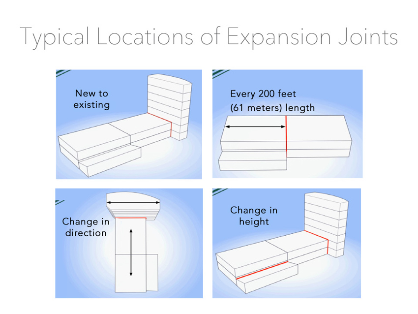
Typical locations for expansion joints are based on the building size, geometry, and three-dimensional makeup.
Typically, the joints need to run continuously through all adjacent planes to fully separate building sections and allow independent movement. This means that any given project scope could include interior joints, exterior joints, or both in things like walls, roofs, floors, building veneers, soffits, parking decks, patios, roofing systems, etc.
Interior versus Exterior Applications
It is easy to assume that exterior expansion joints are subjected to more harsh conditions than interior, but this may not be the case, particularly for joints that cross floors. Interior joints on floors are subject to loading from foot traffic, light maintenance vehicles, or more. Therefore, when determining load requirements, consider what type of traffic will take place. All joint covers are engineered to accommodate a fairly wide range of typical building loads, but it may be important to dig a little deeper to ensure the best cover plate solution is selected. For example, does the owner utilize equipment such as scissors lifts for lighting changes in high-ceiling areas? If it is a hospital, will mobile x-ray machines or gurneys with patients be passing over the joint and therefore require an extremely smooth transition? It is usually best to ensure the worst-case scenarios are considered when specifying systems. A slightly higher front-end cost may alleviate an ongoing facility maintenance headache for years to come.
Form and Appearance
The importance of the form and appearance of covered expansion joints usually depends on the type of spaces where the joints occur and the adjacent finishes. For example, there may be different design criteria for back-of-house conditions than for public corridors or high-end spaces. Depending on the aesthetic being sought and corresponding budget, there are a range of options available to meet different needs. It should never be assumed that one solution works for all expansion joints.
With the above considerations taken into account, we next turn to the different options in the selection of expansion joint systems.
Types of Expansion Joints
There are a number of different types of expansion joints that can be worked into specifications and construction drawings to help assure any building project is properly allowed to move, remains weather and moisture tight, and protects life safety. Each has different characteristics that can make it better suited for certain applications compared to others. To remain water resistive, they need to be detailed and installed properly too. Some of the common types and their typical applications are discussed as follows.
Foam Seals
In certain applications, the use of foam seals in expansion joints provides a solid seal against the elements and moisture protection. Foams can also provide acoustic and insulation properties. As a general rule of thumb, limiting foam seals to applications with a joint width of no more than 8 inches (200 millimeters) or smaller is good practice. Use of foams for expansion joints larger than 8 inches leads to two things: 1) exceeding the foam’s performance characteristics, including possible sagging of the foam seals in vertical applications due the weight of wider sizes, and 2) exponentially higher costs compared to other expansion joint cover solutions.
Fire-rated foam seals are also available and suitable for 6-inch and smaller gaps and conditions where abuse is not likely. These systems are comprised of open-cell polyurethane foam impregnated with a fire-retardant material. These foams can be faced with colored silicone to match a desired decor or design aesthetic. Fire-rated foams are usually lab tested in concrete and cement-board wall conditions (not drywall).
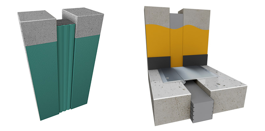
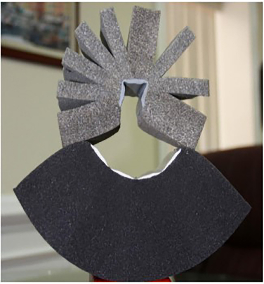
Foam seals come in two basic types: open-cell (left) and closed-cell (right) foam, each
with distinctive properties and characteristics.
When selecting an appropriately sized foam, there are two fundamental types to consider, open-cell or closed-cell foam seals. Open-cell foams provide some breathability and allow for flow-through of water and vapor making them best suited for vertical applications. Like many exterior veneer systems, if moisture becomes trapped in a wall cavity, building systems allow the moisture to wick out. This is a good quality and a major focus to eliminate potential mold issues in vertical applications.
By comparison, closed-cell foams are absolutely watertight and do not allow moisture or bulk water to enter the body of the foam. Closed-cell foams can also be heat-welded at all seams and changes in direction. This is critical for watertight runs, as the seams have the same movement capability as the foam without reliance on adhesives that eventually wear out. They are best suited to horizontal applications where moisture could remain trapped and water penetration cannot be allowed. Closed cell can also be utilized on below-grade vertical applications as support and closure to positive side waterproofing at expansion joints. These are tougher to compress but can be placed under tension (or expand) well.
Whether open- or closed-cell foam is used, it is important to recognize that there is a difference between seals that are manufactured as a layered product and those that are monolithic. Layered foam seals are produced by laminating multiple ½-inch layers of foam together. This is a less costly manufacturing process but can result in a product with reduced life cycle due to the vulnerability of delamination of the various layers from each other or susceptibility to splitting from shear movement. A superior alternative to the layered seal is the monolithic-pour foam seal. As the name implies, by producing a seal in a single pour of the foam material, there are no layers to delaminate. Batch-to-batch variation inherent in layered foam seals is also avoided. While in a compressed state all foams look the same, an argument can be made that specifications calling for foam seals made with “monolithic manufacturing methods” will avoid product failures and claims down the road.
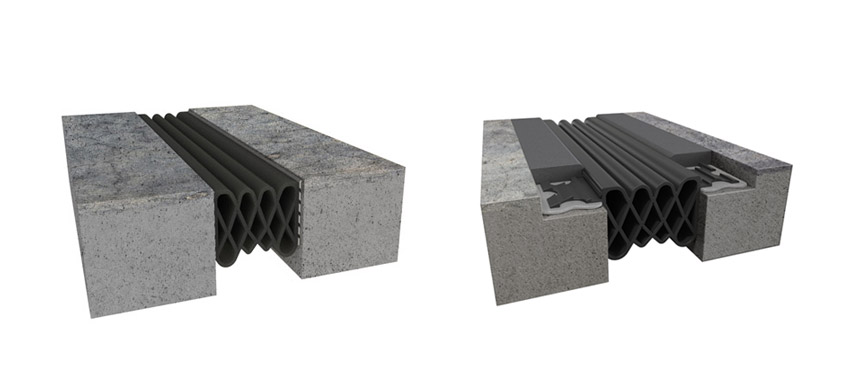
Monolithic foam seals for expansion joints, shown at the bottom of this photo, provide long-term, durable, and waterproof solutions. Laminated foam seals, shown at the top of this photo, are subject to delamination and failure when used in an expansion joint system.
There is one other consideration for foam seals, namely the use of wax impregnation in the foam. Heavy wax-impregnated foams that help keep joints watertight were in use for about 50 years. Some consider the addition of copious amounts of wax as old technology, which is true. However, it is generally regarded that a 2–3 percent wax impregnation is the best alternative since it drastically increases the hydrophobic properties of the body of the foam and extends the seal’s lifespan. Without it, acrylic-only foam can act just like a sponge, meaning that it will soak up and store water. In addition, plain foam assumes an unrealistic expectation of perfect installation of the silicone face and field perimeter caulk seals to keep the foam protected. If the face silicone seal itself is damaged—say, by the tip of a caulk gun jammed between the foam and wall or deck material—leaks will occur. With wax impregnation, the foam seal will remain watertight even if the silicone face seal is compromised because wax does not dry out.
Overall, architects should look closely at the construction of any foam seals and ask questions of the manufacturer as to the makeup of any foam seal being considered.
Compression Seal Systems
As their name implies, compression seal joint systems are installed into a joint, absorbing movement and flexing through compression of the seal. This is an excellent option for exterior application where waterproofing is required. These seals are best employed for heavy pedestrian and moderate vehicle loading, such as plazas, decks, parking garages, etc. Nominal joint sizes for these systems should be in the 1- to 4-inch maximum range. Compression seal systems come in a couple common forms: vehicular “winged” seals or the more moderate epoxied standard seals. Proper use of two-part epoxies ensures solid adhesion to the deck, and heat-welded seams ensure watertight performance. Building aesthetics can be enhanced through the use of colored compression seals.
Compression seals come in different types and colors with very good capabilities to provide a watertight solution
for outdoor horizontal surfaces.
Choosing a manufacturer that utilizes Santoprene for the compression seal material as opposed to EPDM or Neoprene is highly suggested. Santoprene is a type of rubber compound that is widely used in the automotive industry due to its ability to resist abrasion, temperature extremes, and a wide range of chemicals. Its unique ability to allow for heat-welded seams and transitions ensures monolithic runs can be achieved without weak points for water to find. If a fire-rated compression seal is needed, mineral wool strips are often used that are held in place through compression. These are topped with fire caulk sealant to secure the barrier in place and protect it from water infiltration. Fire lab testing of compression systems is typically done for both concrete and drywall conditions.
Hybrid Compression Seal Systems
In locations where plazas and decks are part of the design, tied-in waterproofing is critical to avoid water infiltration into adjacent spaces. In response, manufacturers now offer a new hybrid design of compression seal system that is delivering a greater level of waterproofing in split-slab construction. The key benefit of this system is the use of an integrated counterflashing, which is engineered to channel water away from the joint opening. Of course, to be successful, it is vital that the counterflashing be compatible with the adjacent materials and adhesives being used. Failures in waterproofing can occur if the flashing fails to adhere or reacts to the adhesive. Where load factors require it, metal cover plates can be added over the top of the seal.
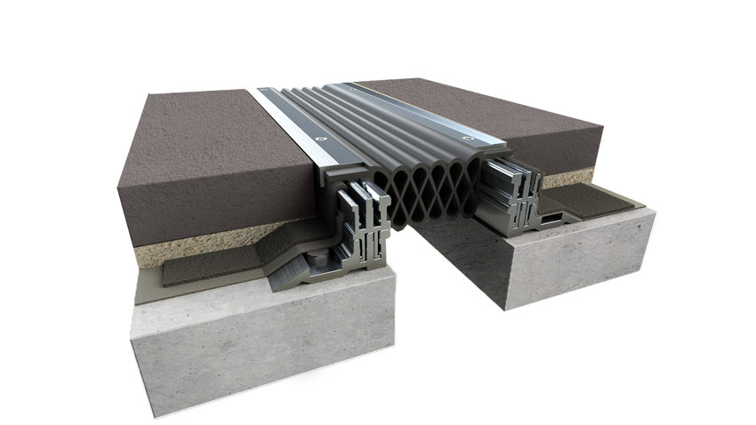
Hybrid compression seal systems bring the best of compressible seals plus the strength of metal frames
for split-slab construction.
Roof Bellows Systems
Expansion joints that pass along a roof membrane need particular attention to remain watertight. Such system use either a TPO or PVC membrane that is bowed up like a bellows so that it flexes to accommodate seismic or thermal movement. As with counterflashing, the seal must run under the metal flanges of the bellows system to allow water to be shed away from the joint opening. Also, a compatible, non-reacting mastic should be used to ensure watertight adhesion of the seal.
Beyond the typical horizontal aspect of a roof bellows expansion joint system, the transitions to walls, parapets, edges, or other building components is critical. Tying in horizontal and vertical joint systems requires transition covers to help maintain watertightness. Architectural drawings and details should always cover this, but the reality is that sometimes transition covers and tie-ins are missed. This can cause significant problems in the watertightness of the roof and adjacent areas.
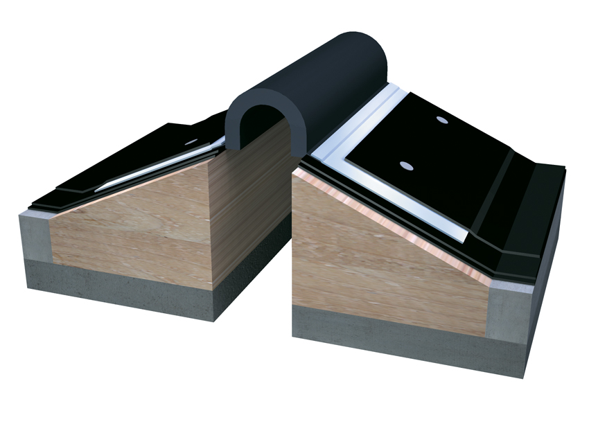
Roof bellows systems are made of flexible EPDM or TPO to cover and protect the expansion joint areas of roofing. Tying these systems into transitions at walls and other components is critical.
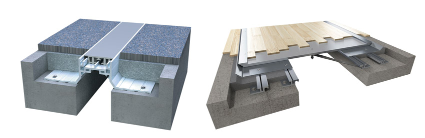
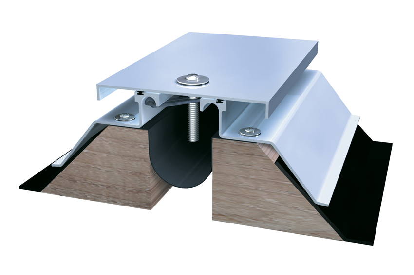
Metal Cover Plate Systems
In many cases, exposed foam or compressible seals will work just fine and provide suitable aesthetics for the particular area of the building in which they are installed. But often there are cases where a metal system is called for to achieve the strength and durability needed. Metal cover plate systems should always be used for joints 6 inches or wider in open structures. Wider joints have surfaces that are exposed to direct loads imposed by tires. A system with shallow, thick frames that are heavy duty offers a high degree of strength in its profile for longevity against the constant vibrations imposed on the cover plates each time a car or other vehicle travels over it. Other attributes to look for include noise dampening and water resistance.
There are two basic types of expansion joint cover solutions in general: surface or recessed mounts. Surface-mounted systems typically are very cost-effective but have wider metal sections that are visible. They are simple to install and great for remodels and additions or projects with particularly tight budgets. Products that are recessed into the deck are flush with the finished flooring and receive no jarring impacts from rolling loads. They also typically have far greater visual appeal since they can be specified with a recessed pan in the middle that can receive a finish material to match the adjacent materials (i.e., flooring, wall material, ceiling, etc.). In this way, the aesthetics of the space are not disrupted by looking at aluminum plates; however, they do require greater trade coordination and are more costly. Nonetheless, they may be the best choice, particularly for interior or exterior systems that are subjected to a lot of pedestrian or light vehicular traffic as noted earlier.
Metal cover systems can be selected that leave the metal exposed (right) or use an infill to match the adjacent surfaces (left).
Reinforced Vapor-Barrier Systems
One solution that can be used in certain applications is to employ a reinforced vapor barrier (RVB) to prevent water infiltration or channel water to drain locations via an integrated drain tube. The critical factor in installation of an RVB for waterproofing is to apply a bed of manufacturer-approved butyl sealant in the concrete block-out or along the frame along the entire length of the expansion joint. This will aid in securing the moisture barrier to the block-out and provide a watertight seal to prevent seepage around the block-out or frame. It is important to make certain that there is always enough drape left in the moisture barrier to ensure the system can fully open to its maximum distance without interference from the expansion cover components.
Reinforced vapor barriers can be added to expansion joint systems provided that they drape appropriately to still allow the proper movement of the expansion joint system.
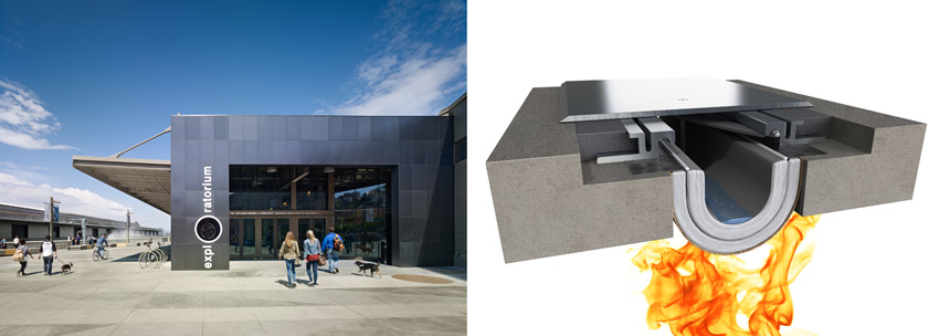
Waterproof Fire-Resistive Joint Systems
We have commented on a few types of expansion joint systems that address fire resistance, such as compressible seals or fire-retardant foams. In addition, fire blankets are the most versatile system, suitable for expansion joint gaps of 2–32 inches and able to withstand high rates of movement. Fire blanket systems come in two forms: ceramic cloths with intumescent layering or graphite sheet goods encasing insulating blankets. In seismic conditions, they allow for approximately 50 percent of joint compression and expansion movement. Some models are able to retain their rating throughout lateral shear movement testing, while others cannot. Fire blankets are tested in concrete, but alternate substrate conditions may also be acceptable.
In all cases, the continuous, uninterrupted installation of the fire barrier is critical for life safety. This is especially true when using fire blankets since they need to be fully and carefully connected to the adjacent concrete surfaces and form a continuous barrier where vertical and horizontal conditions meet. At least one manufacturer has addressed this concern through the use of a modular system that allows separate sections to nest together, creating tight, continuous protection. Further, the edges of the blanket are pre-attached to metal flanges, assuring that the proper seal is obtained instead of relying on field installation to create an uncertain seal. These pre-attached flanges drastically reduce labor costs and ensure a uniform installation for a more reliably continuous seal.
Fire blankets can be specified either to withstand water or not. Those that cannot withstand water exposure and become wet are often rendered useless against smoke, fire, and heat, and even after redrying carry diminished fire resistance. Products that are rated and tested for water exposure during or after construction or for open structures, such as parking facilities and stadiums, provide fire protection even if they become wet. It is important then to select and specify the appropriate material for the water conditions anticipated in the building.
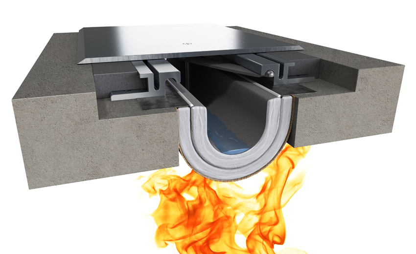
A common fire blanket type of expansion joint system can also be specified to withstand water, making it appropriate for use in a number of exterior settings.
In terms of moisture protection for fire blankets, sometimes a simple EPDM membrane is detailed to be draped and fixed over fire barriers for water-protection purposes. Unfortunately, this approach presents two significant issues. First, EPDM has a fairly low melting point compared to the requirements of fire-testing standards, which reaches 2000 degree Fahrenheit. In this case, the EPDM melts like napalm into the blanket layering, severely reducing its ceramic textile's effectiveness. If it is intended to be applied for temporary protection to keep blankets dry during construction, this is fine, but really is not acceptable for a permanent installation. Second, there are extremely few fire-blanket products on the market that allow for penetrations such as drains. Drains can be easily applied to EPDM, however they then need to be routed out and away above the blanket. Either a sloped waterproofing barrier or specifications of a product that has been tested by certified third-party agencies with a drain penetration should be used. Ideally, penetrations for drains should be avoided to the greatest extent possible.
Proper Installation of Water-Resistant Expansion Joints
Most expansion joints are installed in concrete that needs to be detailed to receive the particular expansion joint system selected. In the field, this means a quality, properly working, and properly water-sealed joint starts and ends with the concrete block-out formed to receive it. The term block-out simply refers to the recess in the concrete floor structure or constructed wall system that is formed by the general contractor or concrete subcontractor. (Alternative regional terminology might refer to a block-out as rebate, knockout, or cutout.) Block-outs are created so there is smooth transition across the joint to allow alignment of adjacent finished surfaces. Once ready, the expansion joint system is installed by a specialty subcontractor qualified to take on the work.
Concrete Work
A few points are important about the concrete work itself to be sure the expansion joint will work properly. The first is accuracy of the concrete since dimensional variability in the pour can lead to difficulties in installing the expansion joint framing and any waterproofing. In addition, cold joints (i.e., regular gaps that occur with the sequential pouring of concrete) should be avoided since gaps means leaks when water is introduced. The other point to remember is that concrete is porous and not waterproof all by itself so water may come through it simply by capillary action. Add in micro-cracks, honeycombing, spalling, form marks, and voids that can occur when concrete is poured and finished, and there are plenty of other ways that water can find its way through concrete. All of this is significant because expansion joints can account for up to 70 percent of contractor callbacks or claims when dealing with this scope of work. In a vast majority of cases, when a contractor says, “The joint is leaking,” failures or anomalies in the block-out or vertical substrates are the usual culprits, not the joint system itself. Therefore it is important to review the concrete details and installation around the expansion joint to be sure that water-penetration issues have been properly addressed there first.
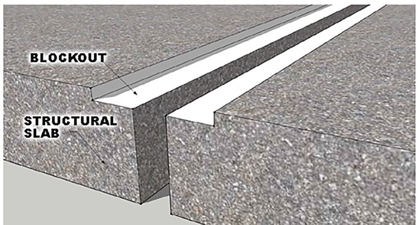
A critical element of the overall success of an expansion joint system has to do with the concrete block-out that is formed to receive the joint system.
Tying in With Other Trades
We have already noted that expansion joints do not exist by themselves, but rather they must be tied in to adjacent building construction. In addition to concrete, this construction can include wood framing or blocking, steel decking, steel studs and joists, exterior finish systems, masonry, and/or glazing. The challenge with these other tie-ins, and a potential failure point, is the reliance on the skilled craftsmen and women to tie their particular installation into adjacent materials and systems well. For instance, if the glazing specification and bid documents allow the glazing contractor to simply install the frame and glass and does not demand that they tie in to, say, an adjacent waterproof vertical expansion joint, it invites problems. The same issue goes the other way too. If a waterproofing contractor installs the expansion joint system and does not tie in to the window glazing, then it is left unaddressed. In this regard, how the scope of work is contracted and managed by the general contractor or construction manager can be critical to having a watertight installation.
While vertical tie-ins with other systems are important, nowhere is this process more important than in roofs. For obvious reasons, these large horizontal areas are going to require the most protection from water (i.e., rain and snow) so any expansion joint systems that cross it need to be coordinated with the waterproofing.
Waterproof roofing membranes come in two fundamental forms: 1) fluid-applied waterproofing assemblies such as hot mopped asphalt, torched felt/asphaltic layers, petroleum-based built-up systems/SBS, or modified bitumen (MB) asphaltic with SBS modifiers; and 2) thermoplastic single-ply membranes, such as EPDM, TPO, or PVC. Given the range of choices and the fact that some materials interact with roofing materials, one of the most critical questions specifiers must ask is whether or not the counterflashing on the expansion joint system is compatible with the deck membrane and adhesives being applied for the roof. If it is not, materials or bonds could be compromised, causing water penetration and damage.
Based on the above, the tie-in of roofing systems with expansion joint membranes is essential to good waterproofing. One failure point can be the reaction and subsequent degradation when roofing materials and adhesives fail to bond with the expansion joint membrane. This is why it is important for the joint membranes to be chemically compatible with the roofing materials. Good detailing by the manufacturer should clearly lay out the recommendations regarding roofing membranes and adhesives that are compatible with the expansion joint counterflashing.
It is clear that the construction documents need to address these points, but diligence during construction is needed too. Sometimes the specified roofing membrane will be substituted or value engineered for another one when construction starts. This fact may or may not get communicated to the manufacturer of the expansion joint systems. Therefore, manufacturers cannot be held liable if the installer and GC/CM do not coordinate material changes, and clear them with the project architect.
Specification Tips
Many architectural offices rely on standard specifications, including CSI/Master Format Section 079500, which covers expansion joints. If these standard specs have not been updated recently, they need to be because vast improvements have occurred in the industry in just the past two years. As we have seen in this course, there are many new and varied product choices with different applications where they excel.
When specifying expansion joints, particularly when there is a need to keep them watertight, there are some ways to help assure general quality of the products and a proper installation. One of the first points to be sure of is that any specified products have been independently tested and can demonstrate passing results for any or all of the following:
- ASTM E283-04: This is a test method for air leakage with pressure differentials through a product specimen.
- ASTM E330-14: This measures how product deflection affects its seal to surrounding substrate.
- ASTM E331-00: This is a test method for water penetration under air pressure difference. It creates a severe vacuum and attempts to draw water/moisture through the specimen and its perimeter to the substrate. The best can reach hurricane levels without failure.
- ASTM 1361-11: This measures thermal performance through a product specimen to determine thermal U-factors (convertible to R-values). This is appropriate to show energy-code compliance and minimize heat transfer between building interiors and exteriors.
- ASTM E90-09: This measures airborne sound transmission loss in building partitions. It is important if minimization of sound transfer through expansion joints is needed.
To determine whether expansion joint products meet any of these standards, or just to determine the best choice of products in general, it is always a good idea to communicate with manufacturers. A quality manufacturer typically provides consultation and technical services for both design and construction professionals alike. The best ones strive be industry thought leaders through the generation of white papers, technical bulletins, and informational videos on hot topics, new product developments, and trends. They can also provide rigorous technical product data and installation instructions to protect the specifier as well as to educate the installer.
To be sure that the installation goes smoothly, specifications should indicate the importance of coordinating with other trades. Per CSI/Master Format, these can include:
- 033000: Cast-in-Place Concrete
- 036000: Grouting
- 040000: Masonry
- 070000: Thermal and Moisture Protection (Roofing, Above- and Below-Grade Waterproofing, Weather Barriers)
- 092000: Plaster and Gypsum Board
- 093000: Tiling
- 096000: Flooring
- 097000: Wall Finishes
Finally, be sure to incorporate clauses requiring inspection under expansion joint covers prior to or after cover plate installation. Waterproofing seams, fire-barrier mounting, and cover plate frame inspections should occur for all of these products.
Conclusion
Expansion joint systems are an integral and necessary part of many buildings to allow for anticipated movement. They also need to be capable of maintaining a watertight seal when they are used on the exterior of buildings. There are a variety of different types of systems that are each suited to particular conditions. By selecting, detailing, and specifying the proper types of expansion joint systems, design professionals can meet functional requirements while allowing the systems to blend in with the building design.
Peter J. Arsenault, FAIA, NCARB, LEED AP, is a nationally known architect, consultant, continuing education presenter, and prolific author advancing building performance through better design. www.pjaarch.com, www.linkedin.com/in/pjaarch